Announcement

Collapse
No announcement yet.

Joulethief SEC exciter and variants

Collapse
X
 
  • Filter
  • Time
  • Show
Clear All
new posts

  • Joule thief for Christmas tree lights. Lights unmodified 120 VAC LED light strings. Uses Davro inductor and transformer. Should light string for 20 hours from AA and 200 hours from D cell.


    Video >>> xee2vids's Channel - YouTube

    Comment


    • Hi.Here is an experiment using a Dr Stiffler type sec exciter using fixed inductors for L1(22uh) and L2(10uh) and a hand wound small L3.
      The interesting thing is tuning is done using a small neo cube magnet on the 10uh L2 choke.
      You can tune for maximum output or if you position the magnet just right you can set up what seems like a secondary oscillation.Here is a vid which shows some of the weird effects.Jonny.
      SEC Exciter. Magnetic tuning - YouTube

      Comment


      • (Replication) Jonnydavro's SEC 15 Variant - 12V / 75 mA - 15 Watt 18" Fluoro

        Happy New Years to all ya great people! Here is a run at replicating jonny's SEC 15 fluoro variant, just a start. I am finding it rather difficult, but then again, this is my first shot at anything originating from the Dr.. anyhow, I did get some results, but a lot of fine tuning before I'll see the magnetic effect I suppose. Thanks to the Dr., jonny, Lidmotor et all.

        Very fun balance of capacitances, tricky for me!

        Cheers, Uploading right now, may take a bit.

        (Replication) Jonnydavro's SEC 15 Variant - 12V / 75 mA - 15 Watt Fluoro - YouTube

        Interestingly, about 5 mins. after I wrote this, I disconnected the circuit, reconnected it, bumped a wire, inadvertantly, and my draw went up to about 130 mA, light output doubled.. What an amazingly sensitive circuit.

        wow.. ok... i get it... the fluoro cant be too close to the coil! bizarre! So for fun, i added a floating L4 connected to nothing at all, and it effectively increased the range of the circuit enabling a second 18" bulb to be lit, and even lowered the draw, some:

        (Replication 2.) Jonnydavro's SEC 15 Variant - 12V / 75 mA - 15 Watt Fluoro - YouTube

        I also noticed if you touch the output wire, it begins to give off a tiny plasma flame too.

        I decided to add another coil, attached to the base, just like the main coil was (L1 in jonny's vid) but I couldn't get it to go. So, I wrapped a sort of primary-like wire around one of the L1's, then a croc lead to a stationary aluminum block that I moved around and adjusted a bit. I'm not sure if it is acting as a feedback, or if it is a capacitance coupling, but it synchronizes everything and is quite interesting in that it allows for the bulb to be more evenly lit across it's length, and gives pretty good output at 80-100 mA/12V.

        (Replication 3.) Jonnydavro's SEC 15 Variant - 12V / 100 mA - 15 Watt Fluoro - YouTube

        In this video I add a second variable capacitor between collector and ground, change the L1 inductor to a potted ferrite 22uH, change the L3b coil to a much smaller air core and dimly light (2) 15 watt bulbs at 12.4V / 30 mA.

        (Replication 4.) Jonnydavro's SEC 15 Variant - 12V / 30 mA - (2) 15 Watt Fluoro - YouTube

        A better higher gain transistor, plasma, and 3 tubes running at about 20 mA
        (Replication 5.) Jonnydavro's SEC 15 Variant - Plasma and HFE - YouTube

        Added a virtual ground, repositioned everything horizontal for better control... 22 hours later, this is the best i can do. If I had of arrived at this, first try, I'd have never believed it. Not sure what the draw is, I can only guess cause it's less than a needle's thickness
        (Replication 6.) Jonnydavro's SEC 15 Variant (Dr. Stiffler) - 12V / ?? mA - 15 Watt 18" Fluoro - YouTube
        Last edited by kcarring; 01-04-2012, 08:06 AM. Reason: edit
        ----------------------------------------------------
        Alberta is under attack... http://rethinkalberta.com/

        Has anyone seen my Bedini Ceiling Fan that pushes the warm air down, and charges batteries as an added bonus? Me neither. 'Bout time I made one!!!!! :P

        Comment


        • Hi Kyle.Firstly I would like to thank you for a great series of vids and also Dr Stiffler for the Sec exciter circuit .
          In your vids you show how important component choice and tuning are and how much time you have to spend to get results but I am so glad that you stuck at it but I don't think you can pack it away just yet as as far as I am aware,in vid no 5,you have the only plasma producing Dr stiffler based Sec exciter on the planet so we need to find out what are the factors which make your build different so this can be replicated.
          Can you build another one so as not to risk losing the configeration that works?
          Can you see if it will work of a wall adapter with its noisy DC.?
          Is the non connected Slayer L1 playing a part?Don't remove the one on your working coil to find out,best to wind another L3.
          Can you get plasma with a variety of L3 coils or just the one you show?
          Is component placement a factor,try reverting back to the Doc's original design with the capasitor of the base and L2 inductor to battery negative.Do you still get plasma?
          Will it work without the variable capasitor?
          Are you using earth ground?Does removal stop plasma?
          What happens when you add an Led protection/indicator or diode?
          Your 22uh potted inductor may be vital,I wonder if it is identifiable and still available?
          Could you possibly post a circuit diagram here for reference?
          Sorry for all the questions Kyle but you do have something different and unique as far as I am aware and I would hate for this to get buried and not developed.Really nice work and thanks for sharing.Jonny.

          Comment


          • @ Kyle
            Some Great videos Kyle,It looks like your off to a good start.

            For this test I'm using a Dr Stiffler type circuit to find the SRF of a coil.
            This will work with very large coil and also very small coils.
            You will just have to retune it with the ferrite rod and the varitable capacitor.

            Off a AA battery this will run from 70uA to 30mA.

            SRF Exciter Circuit - YouTube

            Comment


            • Replication of Kyles Sec exciter plasma discovery

              Hi Kyle .I had to try and replicate your plasma discovery and struck lucky.
              I changed the L3 to a very small 4cm coil which I had previously used for a ferrite slayer exciter and it did not work but the free end of the coil seemed exceedingly long so i cut four inches of it and she fired up.
              The meter was reading 32mA when it started emiting plasma so I cleared stuff away from around the coil it had gone up to 60mA which is still amazingly low for plasma.
              I am using a 10uh choke inductor for both L1 and L2 with a magnet for tuning on L2.I think the reason why the magnet did not work for you is yours is in tune from the get go but mine is not.
              I think everything has to be just right for this to work but I am very happy to have seen plasma from this circuit and such a small coil.Many thanks.Jonny.

              Dr Stiffler Sec exciter variant-Plasma - YouTube

              @Slayer.Hi That circuit is great and pure gold for those trying to replicate the Dr's PSEC where srf of the coil seems to be the major stumbling block.The output looks really good too and I will try it as i would like to get involved with the psec too but have no equipment or the knowledge to use it.
              Probably worth cross posting to the Dr Stiffler SEC thread.
              Thanks for sharing.Jonny.

              Comment


              • Great work by all !

                @Slayer - I can see the meter is a Craftsman, but could you tell me the model number ? I'm seeing vast pricing differences for seemingly similar meters. That's a great method you showed.

                Kyle and Jonny - this stuff is awesome (as they say). Whereas people normally study the tiny intricacies and some are heading toward self running...you guys are unexpectedly blasting power out !


                I hope this is relevant, from personal observations with self made SEC 18's. Running ability and output can be exactly the same from 1.2V as from 3.7V. That's quite the change in voltage and, maybe, you guys could try lower voltages but change capacitances etc, with the goal of plasma attainment ?

                I just goofed majorly, yet found something out which may have use.
                Yesterday I discovered a few 2001 vintage laptop battery cells in the shed and charged one for an hour this afternoon, on a self made 3 coil Bedini wheel. 3.7V Li-Ion. It charged well, so I thought i'd try it on a SEC 18, that was made from junker parts on a CRT monitor.
                I connected the battery the wrong way around, quickly realised and removed the cell. The Green LED (normally white) on the circuit flashed ! It did so a few times with repeated connects/disconnects, until I decided it may not be healthy for the circuit.
                So, these circuits are indeed vastly different to our usual ones...so much to discover.

                Comment


                • Originally posted by Slider2732 View Post
                  Great work by all !

                  @Slayer - I can see the meter is a Craftsman, but could you tell me the model number ? I'm seeing vast pricing differences for seemingly similar meters. That's a great method you showed.

                  Kyle and Jonny - this stuff is awesome (as they say). Whereas people normally study the tiny intricacies and some are heading toward self running...you guys are unexpectedly blasting power out !


                  I hope this is relevant, from personal observations with self made SEC 18's. Running ability and output can be exactly the same from 1.2V as from 3.7V. That's quite the change in voltage and, maybe, you guys could try lower voltages but change capacitances etc, with the goal of plasma attainment ?

                  I just goofed majorly, yet found something out which may have use.
                  Yesterday I discovered a few 2001 vintage laptop battery cells in the shed and charged one for an hour this afternoon, on a self made 3 coil Bedini wheel. 3.7V Li-Ion. It charged well, so I thought i'd try it on a SEC 18, that was made from junker parts on a CRT monitor.
                  I connected the battery the wrong way around, quickly realised and removed the cell. The Green LED (normally white) on the circuit flashed ! It did so a few times with repeated connects/disconnects, until I decided it may not be healthy for the circuit.
                  So, these circuits are indeed vastly different to our usual ones...so much to discover.

                  The meter is a Craftsman Pocket Multimeter 82351.

                  Comment


                  • Thanks for that info

                    Comment


                    • Well, I messed up my coil, and fried my last high gain MPSA06, so I'm down for a bit on this game... but have 100 more on order. I went through 36 transistors to find that last one, but I messed up trying to make it into a high output complementary, fried it. I'm also going to try the 2N5551. It might need to be run in Darlington tho.

                      Interestingly, when my circuit was in resonance, I was using my variable capacitor, and it was somewhere in the 100-115 pF range that it tuned up. At that point, increasing the capacitance beyond about 115, detuned the circuit, and certainly there was decent output at points above, for example @ 800 pF (close to your value) or 1nF.. but... the real magic happened at that 115 pF. Now, once the pigtail was cut... there's nothing in that lower cap range, and only mediocre output available by "pushing the capacitance". This leads me to believe that I was playing in a "node" as the Dr. speaks of. Further evidence of this was that I was able to get high plasma of about .75cm off the pigtail, at only 20 mA and a strong brightness on the bulb. Also, plasma @ 9v. At this "magic point" even my hand 12" away from the setup would effect the circuit, it was really quite interesting. Even where I place the variable capacitor, itself, in it's distance from the main coil, played a factor. Believe it or not, even where I attached the -12v lead of the croc lead to the breadboard, it's position on the rail.. closer to the Vcc, further from Vcc (where it actually joined the rail..." EVEN THAT affected it, suggesting I was tuning the breadboard itself. I could light 2 bulbs to a brightness level @30 mA, I cannot achieve with 60-70 mA now. While completely unproven, and not being qualified to say really, again, I feel I was on a node... but it just as likely it was only self resonance. I wonder though, because I witnessed BLASTS of output I never managed to film... it got me so excited I'd run and get the cam but then it'd taper off. Very strange. Output at 30 mA (12V) that lit up the room to a typical 2 watt level, but just for a moment. Who knows. Wish I had of filmed it better. And as Raui and The Dr. have shown, it's not always where the peak is.. the peak can even lie sometimes (spectrum analyzer). So maybe I'm clueless, maybe I was lucky, maybe it was nothing at all.. I can't honestly say, BUT.. the one thing that is for certain, and was a real interesting aspect, is, that.. the circuit, when it was operating real well, was literally "alive" to play with, a first for me, and quite interesting indeed, when comparing it to how it behaves now. It was like a field of capcitances, every minor movement, placement, taking effect..sometimes producing results that gave off light not previously seen at less than a watt. At 1/3 of a watt. And although completely unscientific, I have 75 videos of light under a watt... I've grown to know what a typical watt of light, in this room, at night... looks like! Anyway it was fun. Time to look at this again, on a scope, signal generator... I'm a math kinda guy, I have to have a piece of wire and measure it out in length and weigh it on a scale. Get it away from all the monitors, RF sources... clutter.. mess... this sort of thing deserves better work practice than I've given it... it was pathetic really, I'm sure the Dr. would shake his head muttering "what a bozo" -- if he saw it, but hey whatever... I'm a noob. He's a scientist. I'll bet he cant cut down a 275 ft. Douglas Fir without killing himself, either, and I can!!! hahha. With all due respect to him though.. Hat's off, I truly believe there is something there... I tend to think I may have only been self resonance, but, I also look at his circuit, and ask myself.. how is that truly possible.. because there is no capacitance in parallel with a primary inductor as in a Slayer or Tesla Coil. I want to see this effect on a meter, somehow... I can't do the random thing forever, I got a 3 yr old kid that deserves my time more than that behaviour does (my "random" stabs at this, I mean), if you know what I mean... LOL. Not to mention 1800 watts of solar panels that need to be made to track the sun!! That's a guaranteed 100 watts of extra free energy, right there... This technology can get good though, I'm pretty convinced!!!! I've had a taste.. I hope someone can take it to the level it NEEDS to get to, to be viable. Reproduceable without 3 devices that cost $3000 that consume 40X the energy being captured, running... It's phenomenal, but far from practicle, at this point. A $100 solar panel still has it beat. Then again, a $100 solar panel has every technology on this whole forum beat, if you ask me. But this one is very very very intriguing, nonetheless. I believe this one could be much more scalable. If you look at what the Doctor is doing, he is dropping in size, and increasing in output... that is a very good trend... very good indeed. Scalability is not all about building enormous, for bigger gain....at all. In fact, that is where you lose scale. Nobody needs 100 ft tall 20 watt wind turbine, for example.

                      cheers mates
                      Last edited by kcarring; 01-06-2012, 07:59 PM. Reason: add
                      ----------------------------------------------------
                      Alberta is under attack... http://rethinkalberta.com/

                      Has anyone seen my Bedini Ceiling Fan that pushes the warm air down, and charges batteries as an added bonus? Me neither. 'Bout time I made one!!!!! :P

                      Comment


                      • Hi all,

                        I may have run into a significant discovery when working on my longitudinal antenna for my moon-bounce project, which appears to also connect to the Tesla Tower:

                        Originally posted by lamare View Post

                        I am just thinking about Tesla's Wardenclyffe tower, after printing the so-called Anderson drawing:

                        Wardenclyffe Tunnels Investigation

                        <snip>

                        (high res version here: http://www.tuks.nl/img/Anderson%20Drawing.jpg )

                        <snip>

                        An interesting detail on this Anderson drawing is that the mains power is fed to the bottom of the shaft, suggesting that the transmitter transformer must have been positioned at the bottom of the 120 feet deeo shaft, a shaft that has been plated with iron.

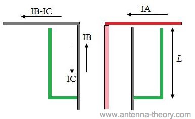
                        This suggests that the shaft may have functioned similar to a sleeve / bazooka balun as I use in my longitudinal dipole antenna:
                        http://www.energeticforum.com/renewa...tml#post172852

                        Such a balun is essentially a short-circuited transmission line:

                        Antenna Theory - Bazooka Baluns

                        The green sleeve in Figures 1 and 2 acts as a transmission line, that is short circuited at the end. From Gauss's law, it is (basically) true that the current on the inside of the outer arm of the bazooka (green line) must be the opposite of that flowing on the outside of the coax (grey line). Hence, the current IC actually sees a short-circuited transmission line. If the length L of the sleeve is chosen to be a quarter-wavelength (at the desired frequency of operation), then the impedance that the current IC sees is infinite (this is the principle of a short-circuited quarter-wave transmission line - see the impedance page for a brief introduction to transmission line theory).
                        So, if you think away the coax core, then you would essentially have a structure that keeps the current (== magnetic component) above the bottom of the shaft in Tesla's case and therefore the only component that can propagate along the 300 feet 1/2 lambda iron "earth grip" starting at the bottom of the shaft would be a longitudinal dielectric wave....

                        <snip>
                        And it appears this principle might also apply to the Gray tube:
                        http://www.energeticforum.com/renewa...tml#post174297


                        What this is about is the principle of how to get an antenna or coil into a longitudinal resonance mode. While for the antenna the problem was how to feed the signal from the coax feed into the antenna, with resonating coils the problem is how to get rid of the magnetic component, the current.

                        I think the same principle, a bazooke/sleeve, can be used in Joulethief / SEC exciter circuits. After all, a coil can be considered to be very similar to an antenna. It is mostly very much shorter.

                        So, the idea is to mount a coil like Slayer's on top of a copper plate, like a PCB, which acts as a reflector, and connect the coil to the copper plate. There would be two taps in this coil, one at 1/4 wavelength and one 1/2 wavelength further on, which is driven using a Hartley oscillator circuit, as I posted before:
                        http://www.energeticforum.com/renewa...tml#post148514

                        From the point where the emitter is connected, a second coil is wound on top of the long one, which has (about?) the same number of turns and is wound using the same wire. The connection near the copper reflector is left open, just like the green sleeve in the above balun illustration. According to the balun theory, the diameter of the short sleeve coil should be like 2-4 times the diameter of the small, long coil.

                        I have made the following drawing to illustrate this:


                        Hi-res version: http://www.tuks.nl/img/Lamare_Sleeve_Coil.jpg

                        The funny thing is that when the coil is in resonance, the currents trough the sleeve coil and main coil are in the opposit direction, wich gets rid of the magnetic component of the propagating wave and you should end up with a longidudinal dielectric wave traveling along the length of the coil. This wave propagates by means of capacitive coupling between the coil windings in a direction perpendicular towards the coil windings. And it propagates with a speed of pi/2 times the propagation speed of transverse waves, which is why you get particular longitudinal and transverse resonance modes in both coils and antenna.

                        At the moment, I don't have much time to experiment with this, because I am concentrating on my moon-bounce project. But may be one of you feels like playing with this...

                        Update: It may be that the sleeve coil will have to be wound in the other direction as the main coil (clockwise vs. counter-clockwise), as Kapanadze did. I don't think so, because the two coils make a 1/2 lambda dipole together, but Im not sure.
                        Last edited by lamare; 01-07-2012, 12:14 AM.

                        Comment


                        • For those interested in finding the same type of meter as used in the video:
                          Craftsman 82351 Multi meter info. Inexpensive and affordable...

                          Craftsman MeterSupport.com

                          Comment


                          • In this video I'm using the same circuit I posed in my previous video.
                            I'm not sure if you can adjust the SRF of all three coils at once because adding another coil changes the SRF of the first.
                            But if all three coils had the same load and would light at the same time.
                            The SRF might be close enought to fine tune them one at a time after getting them close to SRF.

                            SRF Exciter #2 - YouTube

                            Comment


                            • @lamare

                              Very interesting. In your diagram, i see that the sleeve coil's bottom terminates open, and while it's top seems to connect to the emitter, there seems to be an ambiguous part to the diagram in that right beside the word "PVC" -- to be exact, to the right of the letter "c", in "PVC" what is that line... is it wire ... or no?

                              Thanks.

                              When i wrap my head around exactly what u have here, I'll try it.
                              Thanks
                              Kyle
                              ----------------------------------------------------
                              Alberta is under attack... http://rethinkalberta.com/

                              Has anyone seen my Bedini Ceiling Fan that pushes the warm air down, and charges batteries as an added bonus? Me neither. 'Bout time I made one!!!!! :P

                              Comment


                              • Originally posted by kcarring View Post
                                @lamare

                                Very interesting. In your diagram, i see that the sleeve coil's bottom terminates open, and while it's top seems to connect to the emitter, there seems to be an ambiguous part to the diagram in that right beside the word "PVC" -- to be exact, to the right of the letter "c", in "PVC" what is that line... is it wire ... or no?

                                Thanks.

                                When i wrap my head around exactly what u have here, I'll try it.
                                Thanks
                                Kyle

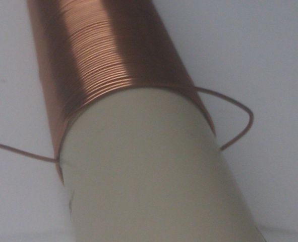
                                The idea was that the word PVC refers to the coils being air-core and wound on pvc tubes, plastic tubes, like the ones used for wiring in a house. Like this coil:


                                There may be a little problem, though, which is that the ratio between longitudinal and transverse propagation speed is not pi/2 by definition in the case of coils, as I posted in the Eric Dollard thread:

                                Originally posted by lamare View Post
                                You have to let go of seeing a coil as consisting of individual windings when thinking about these kinds of things. For example, the Joule-thief / SEC exciter circuits (with air core coils) work on frequencies in the order of 1 to may be 30 MHz, with wavelengths in the order of 10 to 300 meters, way more than the length of the used coils. So, these waves do not "see" the individual coil windings. They "see" the coil basically the same as an antenna consisting of a (meta) material in which the propagation speed of the wave is considerably slower than the propagation speed in air or any "real" material such as a copper tube.


                                As far as I can tell, in "real" media the propagation speed of longitudinal dielectric waves is always pi/2 times the speed of that of transverse waves, irrespective of the medium. So, if you make an antenna out of copper, you can calculate with this pi/2 ratio between the longitudinal and transverse propagation speeds.


                                The interesting thing is that for straight wire resonances, a 1/2 lambda longitudinal wavelength corresponds to 3/4 lambda transverse wavelength:

                                pi/2 * 1/2 = 0,785398163
                                multiply that by 4/3 and we get: 1,04719755

                                So, whenever one of the two waves is in resonance, the other one is almost completely supressed!

                                In other words: with straight wires, be it copper or the mantle of dielectric filled coax cable, you get this pi/2 ratio between propagation speeds and distinct resonance modes, whereby either one of the two wave modes is very dominant, because when one mode is in resonance and therefore amplifies itself as a standing wave, the other mode is supressing itself because it is almost completely out of phase.


                                Another important question is: does this pi/2 ratio also apply to coils?

                                In the "Oscillating Current Transformer" Eric talks about the importance of the width to height ratio of a coil:
                                Tuks DrippingPedia : The Oscillating Current Transformer

                                First of all, he says that the velocity of propation is 1 / sqrt( L_0 * C_0 ) {eq. 5}, whereby the distributed capacitance C is a function of the length to diameter (or height to diameter h/d) ratio, while the inductance L also depends on the coil height and diameter as well as on the number of turns. But the formula for the dependence of C and L on the h/d ratio is different, so by playing with the h/d ratio, you can play with the ratio between L and C.

                                In other words: the ratio of L/C is a function of h/d, a function the geometry of the coil. According to Eric, you get a minimum capacitance when the h/d ratio is equal to one.

                                Now the formula for the propagation speed of 1 / sqrt( L_0 * C_0 ) of course gives the propagation speed of the normal, transverse waves, which have both a magnetic and a dielectric component. The longitudinal dielectric wave, however, propagates without magnetic component and therefore primarily by means of space distributed capacitance.

                                So, I think the ratio of pi/2 between the propagation speeds does not apply to coils, except for coils with a certain h/d ratio.

                                So, now we have a new question: how do we calculate the ratio of the longitudinal vs. transverse propagation speeds in a coil??

                                It may be a better idea to wind the sleeve coil directly on top of the main, long coil in order to get (almost) the same h/d ratio.

                                Another idea would be to use bifilar windings.

                                If you only wind the driving sections bifilar, you get a difference in distributed capacitance between your driving section and single wound section, which means that you can no longer just count the windings in order to determine where the nodes and antinodes will be in your standing wave. And you would also get different propagation speeds in both sections, so if you would want to do that, it may be a good idea to make the long coil a separate coil that is fed by one wire from the oscillator. In that case, you may want to mount the long section perpendicular to the oscillator section, so that the longitudinal waves, which propagates along the length of the coils, do not interfere with one another.


                                If you would wind the whole coil bifilar, you end up with two connections at the other side. If you just connect those together and make sure you end at a voltage node, then you should be able to light a fluorescent.

                                Update: Oops. Then the sleeve would probably not work anymore, because then the current is no longer forced into your sleeve coil, unless you leave the windings of the long coil that form the continuation of the open sleeve coil open at the emitter connection as well.....


                                One would think that it shoud also be possible to somehow transform the longitudinal wave back into a normal, transverse wave and thus generate current. Tesla's TMT suggest that a pancake transformer can be used for such purpose. Having a bifilar wound coil gives you the opportunity to tap both of these windings at different points, which might give additional possibilities.

                                Further insight in Gray's technology may also give further ideas for development:
                                http://www.energeticforum.com/renewa...tml#post175036

                                Essential for the operation of Gray's technology is that the oscillator which appears to exist in his CSET must have been producing impulses rather than harmonic oscillations, whereby you have an (extremely) steep rising edge and a gradually falling edge, the spikes John Bedini likes so much

                                With these kinds of signals, there is a significant difference in the dE/dt during the (positive) rising edge and the (negative) falling edge, which is required in order to magnetize a coil (core). This is what I mailed Mark McKay some time ago on this:

                                I think the trick is not so much in resonance per se as I thought before, but in having steep impulses traveling around your coil in the shape of waves and not so much currents trough the interior of the coil wire. The energy propagated by the fields themselves is much more than the energy released by currents, movements of electrons in a wire, and since their propagation speed is in the order of the speed of light, you can get an extreme impulse of dE/dt traveling around your coil.

                                The problem with HF stuff trough a coil, without DC offset, is that you cannot magnetize a core, because the magnetization direction keeps on flipping back and forth. However, a DC "bias" component together with steep impulses on top, gets you extreme impulses of dE/dt (because of the high wave propagation speed), which is very interesting when we consider Maxwell's correction to Ampere's law:

                                Ampère's circuital law - Wikipedia, the free encyclopedia

                                So, you would need impulse waves with a steep rise time (extreme dE/dt) and a slow fall time (dE/dt much less), which would give you a netto magnetic field, whereby the magnetization can be extremely strong, because of this dE/dt wave propagates extremely fast compared to electron bound currents....

                                I think that is the most basic principle, which explains why spark gaps are so interesting when operated in their negative resistance region, because there you have exactly this DC component combined with a device that can do fast switching and can therefore maintain a resonance mode whereby you have steep impulses (with the character sketched above) traveling along your coil.
                                Update 2: The experiments by Stiffler and earlier Spice simulations ( Article:Free Electric Energy in Theory and Practice - PESWiki ) suggest that with Hartley oscillators using only coils (no external C in your tank circuit) you get a wideband signal, which appears to consist of the natural resonance frequency of your coil and higher order harmonics thereof. This suggests that these kinds of oscillators, with a strong feedback to the transistor, may indeed generate impulses rather than harmonic oscillations (under certain conditions?).

                                However, that does not mean one can easily energize a coil with a coil-based oscillator, because the operation frequency thereof lies in the order of 1 - 30 MHz with long wavelengths expressed in meters. If this theory is correct, then Gray's device must have worked in the GHz range, with wavelengths expressed in centimeters, which is also suggested by the geometry of his CSET.

                                It appears that longitudinal waves with these kinds of short wavelengths are capable of propagating circular around a coil, especially if the circumference of the coil is such that it is a whole number of longitudinal wavelengths, and are thus capable of energizing the coil as well as a core. Provided the waves are impulses, rather than harmonic oscillations.
                                Last edited by lamare; 01-10-2012, 11:01 AM.

                                Comment

                                Working...
                                X