Announcement

Collapse
No announcement yet.

Eccentric Transformer Theory -

Collapse
X
 
  • Filter
  • Time
  • Show
Clear All
new posts

  • #76
    The whole purpose of this thread is to describe how eccentricity in transformer action can lead to a separation or an apparent imbalance in Lenz law.

    This can be shown easily with electrostatics much like Dr Stiffler was doing, or one can go the preferred magnetic route as MK1 has done. There are many things to take into consideration in each build.

    Many of these same goals and observations carry on in other threads also such as the Kapandze thread on OU.com.

    One could view the goal as this....

    We wish to create a disturbance in the environment with a resonant action. We wish to use this kinetic disturbance to create a useful EMF for powering our lives. And...we wish the action of the created EMF to be invisible to the resonant source.

    One of the main problems, is that any loading placed on the induced EMF will be 180 degrees out of phase with the resonant source. As I have shown, this loading may be very much lower than would be expected, and as such an energy gain may be had. However a 4x energy gain can dissapear very very quickly if you have not thought out the problem completely (speaking of maximum energy transfer theorem etc.) In fact if the pick up coil is in any way resonant, it may build up a reactive current, which will be magnified back at the source, very detrimental. One would need to have the pick up inductor, discharge into a capacitor (NEVER INTO ITS OWN INTER WINDING CAPACITANCE) Then the capacitor to load...NEVER BACK TO THE INDUCTOR.

    Remember we have x energy from a coil to deal with. Any resistive load placed directly on it will automatically place us at detriment because of maximum energy transfer theorem. It is the capacitance to which it is discharged that allows us to use the energy efficiently.

    It remains however that what we are looking for is a disconnect mechanism from inducing source, to induced load. We have one good mechanism (eccentricity) to do this with....but this may be taken a step further......

    Comment


    • #77
      Stated once again, the goal is to create a disturbance then use the disturbance without affecting the source.

      Because of the nature of the transformers so far, any action in the induced (pick up coil) will have the same change in time (frequency) as the inducing source. And it is 180 degrees out of phase.

      It would be possible to add a second layer of separation to the transformer if we could have the action at the induced end (secondary or pickup which powers a load) have an entirely different frequency. If the inducing coil were to be at 500Khz, and the output at 60Hz, we would notice that the loading of the secondary would have little effect on the 500khz source....

      At first this seems impossible, cannot be done. But there is a way!

      Imagine if you will Two transmitters with one pickup in between.

      The first transmitter has a frequency of 500,000 Hz, the second Transmitter has a frequency of 500,060 Hz. This creates a beat frequency of 60hz.

      The peak of this crest is roughly 2x in height of the individual waves, because they are in summation. Therefore if placed correctly in the fields, you may have a pick up coil in a location where there is maximum field for a duration of time due to the beat frequency.

      now this cannot in and of itself cause a 60hz oscillation in the pickup. The beat consists of very fast oscillations which gives the “beat” a non polar quality when viewed as an aggregate wave.
      In order to achieve what we want, we could place a powerdered iron core or ferrite, within this field maximum. Next it would be necessary to place a magnetic bias on the core. The core will be able to handle many fields in many orientations until it reaches its saturation point. Then they must fight for the same space. By biasing the core at the desired saturation from our biasing magnets, we have a constant tension in our core. Now when placed within the beat frequency envelope, the core will experience a 60Hz degaussing wave. This 60Hz beat will “scatter the domains” giving them no uniform orientation, then allow them to re align at sixty cycles per second) To a coil wrapped around this core, it will see a change in flux with respect to time, and create an EMF at 60hz also.

      Comment


      • #78
        ah....I see....

        create 2 different frequencies....an interference pattern is created....normally this interference pattern would be destructive....put in an element to suck up the interference pattern and the source frequencies are unaltered

        not really related, or maybe it is...but didn't Royal Rife get past the normal optical magnification barrier by using a few different frequencies of light to illuminate microscopic organisms, and the interference pattern created by the different frequencies became a frequency in the visible spectrum? Whereas normally you can't magnify past a certain point because interference patterns show up and distort the image.

        Comment


        • #79
          Originally posted by SuperCaviTationIstic View Post
          ah....I see....

          create 2 different frequencies....an interference pattern is created....normally this interference pattern would be destructive....put in an element to suck up the interference pattern and the source frequencies are unaltered

          not really related, or maybe it is...but didn't Royal Rife get past the normal optical magnification barrier by using a few different frequencies of light to illuminate microscopic organisms, and the interference pattern created by the different frequencies became a frequency in the visible spectrum? Whereas normally you can't magnify past a certain point because interference patterns show up and distort the image.
          The interference pattern created could be very large, consider the wavelength of a 500,000hz wave, however in the "near field" you will see the field summation and subtraction as a result of the beat frequency. This will essentially be a degaussing wave. This will scatter the ordered biased core, then let it return to coherance.

          I had no idea Rife did what you say, though I have not read a ton on the subject. I would be very interested to read more on this if you have a good source on hand!!! Thanks!

          Comment


          • #80
            Some might also recognize that an "iron" core will alter its inductance approaching saturation. Therefore the following pages can and will be of use in understanding the complete process.

            2SGen, an amazing tiny Solid State Generator by JL Naudin

            and also this pertinent quote from Mr. Eric Dollard,

            " T-Rex Speaks:
            There are some very serious misconceptions in the world of Electrical Engineering today. (The writings of Oliver Heaviside and Proteus Steinmetz gravely warned about this...) Let us start with the YouTube MIT Physics Demo video that Armagdn03 posted a link to on 11-10-2009 on page 2 of this thread. This is a good demonstration for several reasons.

            1.) Glass is a dielectric which can store electrical energy within its physical form. This should be common knowledge and not a surprise to anyone today…

            2.) That this simple fact and reality “blows some people’s minds” clearly illustrates that it’s just all gone way, way, too far… The Einsteinian Lie has succeeded in instilling a mind virus in most everyone and also in confusing Main Stream “Scientists”, who today waste billions of dollars of funding each year, only to chase their own tails in a canonic sequence.

            Chris Carson Built the Rotary Electrostatic Converter. His design was based entirely on my electrical theory and math. It was designed to demonstrate and validate the concept of Synchronous Parameter Variation and the Four Quadrant Theory of Electricity. The device worked well. It had to spin up to around 10,000 RPM. This unit took Chris months to complete; to get all of the parts together, and to get it perfectly balanced and operational. Chris determined that it was starting to exhibit the effects of synthesis of electrical energy from the electrostatic field. This is a result of the variation of capacitance (C in Farrads) with respect to time (T in seconds) which results in a negative conductance G (in Siemens). Hence the generation of electric energy. Then, disinformants, whom I refer to as the “Montauk Crowd” swooped in on him after he completed this device, and he was never the same again, - he died of Brain Cancer a year or two later…

            There was also the Rotary Electromagnetic Converter, constructed by Michael Knots and Peter Lindemann with the help of Chris Carson. This unit exhibited the property of materializing and dematerializing electric energy without regard for the Law of Conservation of Energy. This is another example of synchronous parameter variation. In this case inductance (L in Henrys) time (T in seconds) gave rise to positive resistance (R in Ohms), hence the unaccounted for destruction of electric energy. It must be just as illegal to destroy energy as it is to create it – don’t you think? E is NOT equal to MC squared. There is no Matter to Energy equivalency – this is: The Great White Lie…

            (Where is the video that was made of this device being tested with my Navy electrical switchboard instrumentation anyway????)

            I have a device, built for the Army Air Corps during World War 2, A/N number PP-18/AR Power Converter, which self-sustains the electrical system in my car. It uses the same theory of operation as Chris’s device but involves a different mechanical implementation utilizing a vibrator, several capacitors and 12V and 24V batteries that are connected in parallel through the device, rendering them as one.

            I had a young student from Korea visit me a few years back. He had no problem understanding the basic concept of producing an energy synthesizing apparatus, because his mind was uncontaminated by all of the Bedini/Bearden falsehoods. The term Scalar Wave is an oxymoron, as scalar is part of the propagation constant that is NOT A WAVE! (Idiots!)

            Most are clueless about the importance of the Variation of Inductance and Capacitance with respect to time – and synchronous parameter variations. Read chapter 21 (XXI) titled REACTION MACHINES in Charles Proteus Steinmetz’s book titled “Alternating Current Phenomena”. There is also a Russian paper (brought to me by the Korean student as a gift) titled: “UBER DIE ERREGUNG VON ELETRISCHEN SCHWINGUNGEN DURCH PARAMETERAENDERUNG” von L. Mandelstam und N. Papalexi, published in 1934 in: J. ZEITSCHRIFT FUR (umlaut on the U - as should also be on the first U in the title of the paper) TECHNISCHE PHYSIK Band IV, Heft 1, that continues with what Steinmetz teaches in his books, and takes it all the way (Title translation: Concerning the Excitation of Electrical Waves Through Parameter Changes). In one picture in the paper, there appears to be a brightly glowing incandescent lamp connected to a network, with no apparent connection to a power source. It appears to be an Alexanderson type Mag. Amp. operating in a self oscillation mode. (Alexanderson Patent # 1,328,797 Jan. 20, 1920): Even though my copy of the paper is in Russian, the equations speak for themselves and echo the work of Steinmetz and Alexanderson. Ernst Alexanderson emigrated to America because of Steinmetz’s book, - he was determined to work with Steinmetz after studying it. Steinmetz was forced to reverse many of his equations in later books and was severely criticized by physicist Michael Pupin of Columbia University for not using Maxwell’s ideas and instead developing a methodology that was actually useful and practical for engineers. (Read, “Steinmetz, Engineer and Socialist” written by Ronald R. Kline.) Here it was said that General Electric gave Steinmetz permission to create Electricity form the square root of minus one…

            I personally created so much Electricity form the square root of minus one out of the compressor plant’s synchronous machines at the Richmond Ship-yard that I was working in at the time (which also housed one of my laboratories) that it tripped the reverse power relays of the Richmond substation and shut off all power to the City of Richmond. For that to have happened, means that the City of Richmond was producing more power than it was consuming, hence the reverse power relays tripped and shut the city down. PG & E trucks were there almost immediately. Shortly thereafter, I presented my Four Quadrant Theory to Pacific Gas & Electric Co. executives and engineers on behalf of the lease holder of the shipyard and they became my friends (however they would not allow the shipyard meter to turn backwards). So much for Corporate Suppression… In actuality PG & E would love to have energy sustaining devices connected to their power grid. Profits would soar and pollution would drop. Such devices tend to operate above 500 kva and are not scalable into smaller devices, and therefore are only appropriate for substations. In West Marin, the Tocaloma PG & E substation on the Ignacio/Olema 66 kv line, has only one line for both the input and output. It represents the vestige of such devices, - an installation that has been in operation for at least 70 years. Today, probably no one in PG& E, even knows how it all works. (Don’t expect the lights to stay on for too much longer… today, engineers have been replaced by lawyers and safety has been replaced by insurance. It’s a LET-IT-BURN policy…)
            At the time, the Bolinas RCA-Marconi Station, through corporate encouragement by RCA and Bell Telephone, gave me free run of that site to set up one of my laboratories. My plan was to produce a system utilizing no rotating machinery but only static devices, such as coils and condensers in an Alexanderson configuration to possibly power the town of Bolinas and at least provide PG & E with all of their reactive power needs. The network experiments would consume no energy to operate and therefore cost nothing. The plan was to use the electrical substation on-site to connect to PG & E’s grid, giving power to them for free, in exchange for being able to use the 12kv power line for my experiments. Everything of importance including engineering records and notes as well the equipment at the Bolinas RCA-Marconi Station was destroyed by State of California Environmentalists through Jerry Brown (former California Governor) and the environmental politician Burr Henneman, this in conjunction with The National Park Service. The NPS is an EMBEDDED FOREIGN ORGANIZATION within the United States Government. Massive quantities of polychlorinated biphenyls and mercury were released into the environment by environmentalists in their endeavor to destroy the Station as quickly as possible. (See the link already posted by phi1.62 on 01-21-2009 on page 2 of this thread) The same group destroyed my Civil Defense Facility in the town of Bolinas which was on the property of Nashama Franklin. The same property was embezzled afterwards from Ms. Franklin by the same crowd that embezzled the Reynolds funding.

            Also in Bolinas, U.S. Coast Guard Communication Station NMC worked with me on certain problems they were having and their reutilization of the RCA site. This enviro-group went to NMC and warned them of the consequences of doing business with Eric Dollard. Today NMC cannot even be heard in Half Moon Bay 50 miles away, if they are on the air at all. (Who needs Bin Laden?) Who doesn’t like Tesla then? Is it the government? (no). Is it the environmentalists? (you got it) They call themselves Commonweal. Altman link

            As far as inventing the log periodic: it was invented by Raymond H. Du Hammel, I believe, as an Air Force Project and the University of California Berkeley was where most of the work was done. Check patent number: 2,985,879, it is a fascinating design.

            On the other hand, I did invent the Log Periodic Multiple Wave Oscillator based on the initial Lakhovsky patent. I got rid of all the bull and added a Golden Ratio Log Periodic antenna which was etched out of a double sided printed circuit board and then Gold plated which was widely sold and probably still is, for which I did and do not receive a dime. It seems to have some sort of radionic effect even with out power being applied.

            Individuals in the guise of Borderland Sciences embezzled $50,000, money that R. Joshua Reynolds had provided me with to continue my research. At the “Last Supper” where Joshua invited everyone for dinner, (everyone that he had funded with millions of dollars that is) he cut off funding for Andrea Puharic et al (the Soviet Scalar Conspirators) and pronounced that I had done more on USDA food stamps than any one else that he had funded. Needless to say, I made no friends at the dinner table that night… The Voodoo was hideous…

            Am I concerned about the CIA, the NSA or any other alphabet soup organizations’ supposed suppression or retribution?... No! Common swine that’s who I am concerned about. An example of this is a situation that I encountered in Montana. A group in Missoula (which was later found out to be a group of international criminals) showed up to “HELP ME” and in trade I would help them extract gold from spent tailings utilizing Tesla methodologies. They helped me alright, by entrapping me, assaulting me and stealing my classic Celica and threatened to kill me if I were to do anything about it. They strong armed their way into my Desert laboratory to steal all related equipment. The property owner of the desert lab died shortly thereafter, within weeks of Chris Carson’s death. Friends of yours Peter?

            As is well known, I was the last engineer involved with getting the Integratron operational. My efforts were thwarted and ruined, not by the Men in Black, but rather by the Woman in White. Today the Integratron is a Goddess worship temple…

            So in light of all the above, why should Eric Dollard involve himself in the useless or criminal behavior of others. There are those who wish to republish my earlier writings and to make this information freely available to everyone. Unfortunately, much of it has already gone to the dump. I have no interest in teaching anyone about Tesla except under the department of the Navy or the likes thereof. The door is shut!


            73 DE N6KPH SK"

            Comment


            • #81
              @all

              Sorry for the late reply , here is where i posted all the details and process of construction , i however did not have time to work on it lately .

              Fibonacci, platonic solids and Vortex coils around page 10 you see the construction of the coil pictured .

              I posted on you tube most of my findings ... you can see also other early prototypes .

              YouTube - abramrk1's Channel


              Mark

              Comment


              • #82
                Originally posted by Armagdn03 View Post

                " T-Rex Speaks:
                There are some very serious misconceptions in the world of Electrical Engineering today. (The writings of Oliver Heaviside and Proteus Steinmetz gravely warned about this...) Let us start with the YouTube MIT Physics Demo video that Armagdn03 posted a link to on 11-10-2009 on page 2 of this thread. This is a good demonstration for several reasons.


                73 DE N6KPH SK"
                the link is here :

                http://www.energeticforum.com/renewa...dollard-2.html

                Comment


                • #83
                  See images
                  Attached Files

                  Comment


                  • #84
                    Sorry i'm so late

                    Originally posted by Armagdn03 View Post
                    The transformer process in current light generally refers to a passive electrical component which is designed to take energy at one potential and current state on the input, and output at a differing potential and current state based on well defined and accepted ratios. Generally the transformer is of inductive character defined by two electrically separate conductors wound about the same core. It is expected that the power consumable on the output will be equal and opposite to the power consumed from the input minus losses. This is a feature of design only, and holds true to most modern transformers. In eccentric transformer theory, we will examine various forms of transformer which are geometrically wound about individual centers. We will take note how , The bulk of the transformer process can be described by taking an examination of the laws of induction, but it will be shown also that other phenomenon describe the transformation process, but are hidden to us through conventional design. Both capacitive and inductive transformer coupling will be addressed and calculations presented for each.

                    Inductive Transformer action

                    The standard transformer According to Faraday's law (put in this convenient permutation)

                    Voltage Generated = (-N)(delta (BA))/delta t)

                    Where we have replaced the unit of inductance with its terms:
                    -N = number of turns
                    B = Magnetic field strength in Tesla
                    A = Area of turns

                    Assuming the primary and secondary are concentric (about the same center) Lenz law applies in the standard way, giving us an equal and opposite EMF equating to equal and opposite energy states on both primary and secondary minus losses. This essentially describes the bulk of the "transformation" process mechanism for this example. It may not be readily apparent, but the Inverse Squared law of electromagnetic radiation is also in effect, though it is hidden to us in conventional designs.
                    According to the inverse squared law, as we increase the diameter of the secondary (around the primary, concentrically) the magnitude of the EMF created by the primary will decrease accordingly. As we get one radius away from the primary, the magnitude will be 1/4 of the source. But we have also increased area by a factor of four (area of a circle increases by factor of 4 with a doubling of the radius). Therefore in the equation for Faraday's law, the factors of 1/4 and 4 cancel out for no net effect.
                    This clearly shows both in practice, and mathematical convenience, that when sharing a common center, Faraday's law creates an Equal and Opposite reaction to any change with respect to time in the current of the primary. However, if the primary and secondary do NOT share centers, a new area of study becomes of interest.
                    If the secondary is wound about a separate center, sitting adjacent to the primary, Lenz law does not behave in the familiar way. The secondary coil will feel a fraction of the field emitted by the primary according to the inverse square law of electromagnetics. For example:

                    Primary coil: 16 units Field strength
                    Secondary coil: 2r away from centre of primary
                    secondary coil: “Feels”: 4 units Field strength

                    Because of the inverse square law, and our geometric spacing, we can see that the secondary at distance 2r will see only Ľ of the emf as if it had been wound about the same centre as the primary. The secondary will now react per Lenz law to push back on the oscillations of the primary coil. This opposing oscillation must now travel back to the primary across free space, and according to the inverse squared law once again, its magnitude will decrease. If we decrease by a factor of 4 once more, we can see that the primary coil will feel a BEMF of only 1unit. To summarize:

                    Primary coil:
                    16 units of field radiating
                    Secondary coil:
                    Feels 4 units of field from primary
                    Creates equal and opposite 4 units per Lenz Law (BEMF)
                    Primary coil:
                    Feels 1 unit of BEMF From secondary

                    So we have expended 16 units, to "create" 4, which pushes back for a total of 1. Hugely inefficient, unless you consider the primary to be a charge conserving resonant structure. In this situation, minus the average reduction due to Q loss, 16 units gets reduced by the BEMF for 1, to create 4 units. The rest of the charge within the primary is conserved and reused in succeeding cycles. Thus we find that the primary consumes 1 unit of energy (minus loss) to create 4 units of energy. Here the "equal and opposite" apparent in all areas of electromagnetics has not been circumvented in any way, simply the geometry has been changed to our advantage.


                    This same effect can also be calculated using only the capacitive coupling for transformer action.
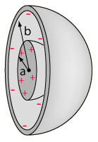
                    Capacitors can be arranged in simple geometric ways to act as transformers much the same way inductors can. Such a transformer would appear as a sphere, with a sphere around it concentrically. Because the energy states of both “plates” of our capacitor must be equal, but, the surface area of the inner sphere is less than that of the outer sphere, it will have higher charge density than the outer sphere. The ratio of sizes of the inner sphere to the outer sphere can manipulate the charge density on each to give us transformer action in well known ratios. The mathematics are a direct derivation of
                    Gauss' law. Because both spheres are about the same center, you will find a situation identical to the transformer described in the previous section. When a change in potential on one sphere occurs, it is mirrored in the second sphere equal and opposite.


                    One may remove the concentricity aspect of this transformer, and place the spheres on eccentric centers. Here one sphere will be physically next to the other. A simple mental experiment will show that we are left with a similar situation to the transformer action described above. We will assume once again that the primary sphere emits a field of 16 units and both spheres have equal capacitance. The second capacitor sitting 2r away will feel only 4 units of potential with respect to ground, once again due to the inverse squared law of electromagnetics. The secondary capacitor is allowed to charge to this 4 unit potential. In practice the primary sphere will be attached to an inductor which allows for a resonant circuit. Each cycle the sphere discharges its energy back into the inductor and it is recycled. Because our secondary is now charged, and emitting its own field of 4 units, the primary cannot discharge 100% of its energy back into the inductor. The secondary per inverse squared mechanics will have the primary sitting in its field and the primary will feel 1 unit of field. Now where the primary would have discharged all 16 units back into the inductor for re use, it instead only returns 15 units because one unit is held stationary by the charge found on the secondary. Once again we find ourselves expending 1 unit to create 4 total minus loss.

                    It can be seen in both cases that by simply changing the geometric relations of primary and secondary, energy can be created. In similar fashion, and through creative design energy can also be destroyed.

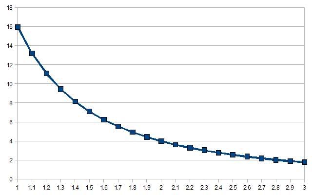
                    It can be shown that as one gets further from the source the signal received will decrease as shown in the graph below. The number 1 on the X axis represents concentric arrangement. As the centers depart from one another, the field felt decreases accordingly.


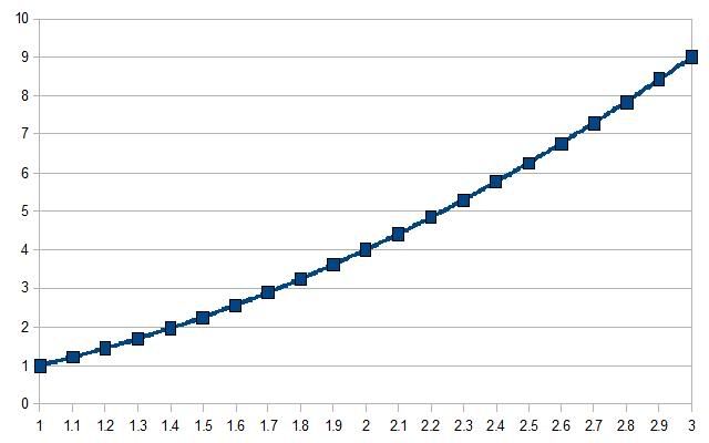
                    It can also be surmised that what is felt by the secondary, is returned in Lenz like fassion to the primary, constituting a feedback to the source, and equating to work done. The ratio of power induced on the secondary to power returned to source in Lenz like reactions can be considered a multiplicaiton ratio. So for example with our previous calculations, as the secondary feels 4 units, and returns to the source 1unit of detraction, the multiplication ratio is 4.

                    It can be seen when graphing this in the chart below, that as one moves further and further from the source, the process becomes more and more efficient. At 3r it becomes a multiplication ratio of 9, at 4r, 16 and so on.


                    It must be realized though that while the process becomes more and more efficient, the average power felt by the secondary decreases. We can see that the graphs have inverse relations in their slopes, and so there will be one point at which they cross. This intersection in the graphs represents the best possible agreement between power felt by the secondary, and the calculated multiplication factor. Mathematically the two equations can be set to one another used to derive the graphs, and find a common solution.

                    Thanks for viewing

                    Andrew Manrique
                    Hi, like I said sorry for being late (hopefully someone replies), but I am curious as to how you have allowed for the energy used to 'charge' the secondary sphere. You say 16 units go in, 4 are used to charge the secondary, and then 1 is reflected back to the primary from the ususal 1/R2 law etc. I think it would also be prudent to rigorously define what units you are dealing with (i.e. 16 units means nothing; say 16Tesla, or Ampere-turns, or Webers; all have a different meaning). Please beleive me when I say that i'm not trying to be a jerk, but it sounds like pseudo-science without a rigorous,harsh definition and clear explaination of every single step.

                    The thing that bothers me ultimately, is that you sat 4 'units' are received by the secondary. Then these 4 untis are absorbed and not available as recoverable energy from the primary!! That is: 16 units go in, 4 disappear to charge the secondary sphere. That leaves 12 units, not 16!!!!!!!!!! So when you get the 1 unit back, you have 13 units........ Sounds like a perfectly clear explaination of the conservation law to me. That law has stood for 150 years; I have been involved in this field for 10 of those years. I'm not saying that I can't be proven wrong, but give an explaination that involves a true dimensional analysis, and a powerful mathematical explaination why Maxwell should eat his hat. Until then, i'm going to beleive that you and all others like you have forgotten that energy is REQUIRED to charge the secondary sphere. Unless, or course, it's got something to do with the Earth's magnetic field providing free energy or something, in which case Maxwell still wears his hat...

                    Like I said i'm not a jerk trying to hurt anyone, but i've spent a long time developong a conclusinve model in my mind of how classical electromagnetism works, and I can't imagine that placing two conducting spheres next to each other, and feeding one with resonant AC, would give you free energy?????!!!!!!!! As if someone else hasn't found it by now????!!!!

                    Comment


                    • #85
                      good thread but I think is not active
                      Last edited by boguslaw; 04-15-2011, 09:01 PM. Reason: spell

                      Comment


                      • #86
                        Thank you!

                        Hi everybody, first of all Armageddon I have to thank you so much for making your idea clear and easy to grasp, after I read your first post in the eccentric TF tread at OU.com I understand your videos so much better now.
                        A real aha experience!

                        @Peter B
                        It is normal to use symbols or placeholders to make formulas and relationships simpler, such as using V for velocity instead of limiting it to either feets per second or meters per second etc.

                        If I understand the basic idea, eccentricity is important, but what is really important is the transmitter and receiver role in this kind of device.
                        In a standard transformer what is sought is almost perfect coupling between the coils, and any deviation from that is equated to as a loss.


                        Again what Armageddon has said explains it if digested properly.
                        Lets just imagine that we have a transmitter coil of dimensions and alternating current capable of creating a B field of 80 gauss.
                        If we had a receiver coil superimposed over the transmitter it should then had felt the full 80 gauss field.
                        So, if we then move it further away (can be done in many variants), so that the distance between them is as proposed 2 times the transmitter's radius, the 80 gauss should have been reduced 16 times down to 5 gauss as per the law of squares. This will then be sensed and converted to emf at the receiver, and once used to move current will generate the resulting counter magnetic field (Lenz's law).

                        Now as has been said, that emitted counter magnetic field will undergo the same reduction of intensity as the source field did, which means that the transmitting coil will experience whatever is re-emitted from the receiver as 16 times smaller than it originally was.


                        In a standard transformer the back emf will always be very close to 100 percent because this is how we have decided that they are to be constructed.
                        I think it is very easy to forget important questions when you are told that "this is how it works, and it can work no other way".

                        Our history is littered with incredible claims of devices and stories of persecution as the resulting response. I do not believe all of these are faked, and the more I look into the human side of them the more credible many of them sounds. As I think is mentioned Hubbard's coil seems to fit with this theory.
                        It also seems to go very nicely together with this video from Lidmotor: YouTube - Motor - Generator running on a capacitor.ASF

                        All the best
                        Julian
                        Last edited by Naboo; 04-15-2011, 08:11 PM.

                        Comment


                        • #87
                          Originally posted by Naboo View Post
                          Hi everybody, first of all Armageddon I have to thank you so much for making your idea clear and easy to grasp, after I read your first post in the eccentric TF tread at OU.com I understand your videos so much better now.
                          A real aha experience!

                          @Peter B
                          It is normal to use symbols or placeholders to make formulas and relationships simpler, such as using V for velocity instead of limiting it to either feets per second or meters per second etc.

                          If I understand the basic idea, eccentricity is important, but what is really important is the transmitter and receiver role in this kind of device.
                          In a standard transformer what is sought is almost perfect coupling between the coils, and any deviation from that is equated to as a loss.


                          Again what Armageddon has said explains it if digested properly.
                          Lets just imagine that we have a transmitter coil of dimensions and alternating current capable of creating a B field of 80 gauss.
                          If we had a receiver coil superimposed over the transmitter it should then had felt the full 80 gauss field.
                          So, if we then move it further away (can be done in many variants), so that the distance between them is as proposed 2 times the transmitter's radius, the 80 gauss should have been reduced 16 times down to 5 gauss as per the law of squares. This will then be sensed and converted to emf at the receiver, and once used to move current will generate the resulting counter magnetic field (Lenz's law).

                          Now as has been said, that emitted counter magnetic field will undergo the same reduction of intensity as the source field did, which means that the transmitting coil will experience whatever is re-emitted from the receiver as 16 times smaller than it originally was.


                          In a standard transformer the back emf will always be very close to 100 percent because this is how we have decided that they are to be constructed.
                          I think it is very easy to forget important questions when you are told that "this is how it works, and it can work no other way".

                          Our history is littered with incredible claims of devices and stories of persecution as the resulting response. I do not believe all of these are faked, and the more I look into the human side of them the more credible many of them sounds. As I think is mentioned Hubbard's coil seems to fit with this theory.
                          It also seems to go very nicely together with this video from Lidmotor: YouTube - Motor - Generator running on a capacitor.ASF

                          All the best
                          Julian
                          Wow, my thread is alive again!

                          This is correct, I used "units" to show relationships without muddling up the concept with other things.

                          In reality, the unit I use, is an electrostatic field strength unit, volts.

                          What is interesting is that because this is an LC network in reality (the sun and secondary coils) the phase relationship between the B field energy and the Potential energy will be out of phase 90 degrees, one will be at max while other will be at min and vice versa.

                          Why this is interesting is that because when on the oscilloscope we measure say a peak of 10 volts, this means that there is no magnetic energy present at that moment. Now if you know your capacitance you can figure out how much that 10 volts represents. this is how......


                          We know that the energy in a capacitor is 1/2 Capacitance * Voltage^2

                          Therefore say our capacitance is 2 farads, our energy is 10^2 or 100.

                          This actually arises of what is called the Pythagorean Therum, bar none one of the most important equations ever known to man.

                          This is the sum of what I learned from my experiments here.

                          1) There is a point of maximum transmission which tends to fall about the 2r measurement of the primary.

                          2) The energy in the system is conserved, no extra lunch yet when energy not electrostatic field units are taken into account.

                          3) A HIGHER IMPEDANCE POINT can be reached with two coils than could ever be reached with one alone!!! that in itself is incredible, but for reasons which are beyond the grasp of most at the moment.

                          4)The parent coil alone stratefies the air around it, the addition of another coil makes, orbits, or areas of maximum transmission appear that were not there before.


                          5)This can be done on a wide band oscillator like SEC as well, the 2r relationship changes because of the ultra wide band emissions.) [/B]

                          There is one other incredible aspect to this which I will expand upon,
                          this is how I believe Morray created his device.

                          Comment


                          • #88
                            Thank you for all the detail. A lot of this stuff seems to be beyond me to be honest, but I am learning.

                            I feel one aspect need to be understood better:
                            The thing that bothers me ultimately, is that you say 4 'units' are received by the secondary. Then these 4 units are absorbed and not available as recoverable energy from the primary!! That is: 16 units go in, 4 disappear to charge the secondary sphere. That leaves 12 units, not 16!!!!!!!!!! So when you get the 1 unit back, you have 13 units........ Sounds like a perfectly clear explanation of the conservation law to me.
                            This is very interesting in my opinion, and make me relate to what Don Smith has said, even though I know he is kind of controversial to many.

                            Because the thing is, if you charge a sphere inductively from another sphere (move them close together or excite the source sphere), you will not experience a load. In fact at this point it will as Don has said only copy the potential from the source field. The load appears when we wish to change the source voltage again, or move the source sphere away, as the receiving sphere will hold the source at its current value.
                            This will then be the electric take on Lenz's law, or rather, Lenz's law is probably a result of this fact.

                            So it is basically like producing EMF in coils of wire as well. Inducing EMF doesn't cost anything, but once it moves current there will be created a field which opposes the change, but not before.
                            And lastly, as this opposing field has to move the same distance as the source field, it should be reduced by the same amount... unless of course, something like described in this link happens:
                            Nikola Tesla Page, Tesla's power receiver

                            Julian
                            Last edited by Naboo; 04-19-2011, 02:20 PM.

                            Comment


                            • #89
                              The thing is I wrote this whole text using Voltage, which is not energy, to convert you need to realize how the law of squares comes into play, hence my last post.

                              This is conservation of energy, however the reasoning is not right that was quoted

                              The problem was, I was writing in volts and nobody was converting that to energy. Which was confusing on my part. To re explain was taking alot of time, so I just did my own thing and stopped posting because it was slowing me down.


                              But you are correct, what I was hoping someone would stumble upon the fact that voltage and energy are not the same, and I have been toying with for a while is what happens when we break the symmetrical condition.

                              For example, both spheres are spheres and radiate by the inverse squared law. one always feels 1/4 of the other at distance 2r.

                              BUT, what happens if the transmitter is a laser (coherent EM waves in a beam like arrangement). Now the resonant pick up can stand 100% within the EM field of the transmitter without signal loss (look up audio spotlight, acoustic laser etc.) But its BEMF must still be symmetrical and the source will recieve 1/4 field strength. This is where this was all going. THis is why I was briefly interested in the Magnetic Beam Amplifier, and Dr. Stiffler had a beam device which he never shared which might have fit the bill.

                              This concept (eccentric transformer) is actually alive and well in Dr. Stifflers private research group and has a lot to do with the 3 coil setup.

                              Then there is the concept of the Missing Fundamental Generator which takes these fundamental concepts and places them into practice. I believe I posted its concept here post # 05-22-2010 12:49 PM. This is a working device, This uses resonance to achieve results in a similar way to Orbo and Naudin's S2gen device. The concept simplified is to take 2 frequencies, super impose to come up with a third frequency outside the harmonic range (bandwidth) of the first two oscillators, then pick this up with tuned receiver. The BEMF of the 3d frequency will not affect the transmitters in the traditional way because of a one octave or more difference.

                              What is the most important thing to take from this thread???

                              Around a transmitter is a point of maximum power transmission, this is the transmission analogue of the maximum power theorem. When secondaries are placed within this preferred radius, a HIGHER impedance point can be reached than with a single coil!!!!!!!! THAT IS HUGE. The system Q goes drastically increases, power loss decreases, transmission decreases, conservation of energy within the structure increases.


                              Imagine that the existence of the secondary is DEPENDENT on the undulations from the transmitter. Maybe the earth EXISTS because the sun keeps feeding it at one of its maximum transmission points. THen the orbit is not a careful balance of centrifugal force and gravity, rather the earth is and EDDY current, being kept in orbit because cannot leave its orbit, or it is no longer tied to the sum.

                              In fact I would venture to say that the sum of the energy of the sun, INCLUDES the energy of each of the planets, they are all one and the same.

                              Just like the energy in a water flow includes the energy bound in eddies along the periphery. thought it may not be conventionally noted.

                              We are talking about a geometric setup, based on the unit circle and law of squares which possibly peaks into how the world naturally orders itself.

                              Comment


                              • #90
                                Also, User Raui has been kind enough to set me up a place to post my thoughts, I will mainly be posting there.

                                Armagdn03's Blog | Your description here

                                This will tie together this thread with all my others, as they are related.

                                Comment

                                Working...
                                X