The transformer process in current light generally refers to a passive electrical component which is designed to take energy at one potential and current state on the input, and output at a differing potential and current state based on well defined and accepted ratios. Generally the transformer is of inductive character defined by two electrically separate conductors wound about the same core. It is expected that the power consumable on the output will be equal and opposite to the power consumed from the input minus losses. This is a feature of design only, and holds true to most modern transformers. In eccentric transformer theory, we will examine various forms of transformer which are geometrically wound about individual centers. We will take note how , The bulk of the transformer process can be described by taking an examination of the laws of induction, but it will be shown also that other phenomenon describe the transformation process, but are hidden to us through conventional design. Both capacitive and inductive transformer coupling will be addressed and calculations presented for each.
Inductive Transformer action
The standard transformer According to Faraday's law (put in this convenient permutation)
Voltage Generated = (-N)(delta (BA))/delta t)
Where we have replaced the unit of inductance with its terms:
-N = number of turns
B = Magnetic field strength in Tesla
A = Area of turns
Assuming the primary and secondary are concentric (about the same center) Lenz law applies in the standard way, giving us an equal and opposite EMF equating to equal and opposite energy states on both primary and secondary minus losses. This essentially describes the bulk of the "transformation" process mechanism for this example. It may not be readily apparent, but the Inverse Squared law of electromagnetic radiation is also in effect, though it is hidden to us in conventional designs.
According to the inverse squared law, as we increase the diameter of the secondary (around the primary, concentrically) the magnitude of the EMF created by the primary will decrease accordingly. As we get one radius away from the primary, the magnitude will be 1/4 of the source. But we have also increased area by a factor of four (area of a circle increases by factor of 4 with a doubling of the radius). Therefore in the equation for Faraday's law, the factors of 1/4 and 4 cancel out for no net effect.
This clearly shows both in practice, and mathematical convenience, that when sharing a common center, Faraday's law creates an Equal and Opposite reaction to any change with respect to time in the current of the primary. However, if the primary and secondary do NOT share centers, a new area of study becomes of interest.
If the secondary is wound about a separate center, sitting adjacent to the primary, Lenz law does not behave in the familiar way. The secondary coil will feel a fraction of the field emitted by the primary according to the inverse square law of electromagnetics. For example:
Primary coil: 16 units Field strength
Secondary coil: 2r away from centre of primary
secondary coil: “Feels”: 4 units Field strength
Because of the inverse square law, and our geometric spacing, we can see that the secondary at distance 2r will see only ¼ of the emf as if it had been wound about the same centre as the primary. The secondary will now react per Lenz law to push back on the oscillations of the primary coil. This opposing oscillation must now travel back to the primary across free space, and according to the inverse squared law once again, its magnitude will decrease. If we decrease by a factor of 4 once more, we can see that the primary coil will feel a BEMF of only 1unit. To summarize:
Primary coil:
16 units of field radiating
Secondary coil:
Feels 4 units of field from primary
Creates equal and opposite 4 units per Lenz Law (BEMF)
Primary coil:
Feels 1 unit of BEMF From secondary
So we have expended 16 units, to "create" 4, which pushes back for a total of 1. Hugely inefficient, unless you consider the primary to be a charge conserving resonant structure. In this situation, minus the average reduction due to Q loss, 16 units gets reduced by the BEMF for 1, to create 4 units. The rest of the charge within the primary is conserved and reused in succeeding cycles. Thus we find that the primary consumes 1 unit of energy (minus loss) to create 4 units of energy. Here the "equal and opposite" apparent in all areas of electromagnetics has not been circumvented in any way, simply the geometry has been changed to our advantage.
This same effect can also be calculated using only the capacitive coupling for transformer action.
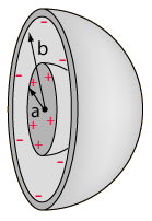
Capacitors can be arranged in simple geometric ways to act as transformers much the same way inductors can. Such a transformer would appear as a sphere, with a sphere around it concentrically. Because the energy states of both “plates” of our capacitor must be equal, but, the surface area of the inner sphere is less than that of the outer sphere, it will have higher charge density than the outer sphere. The ratio of sizes of the inner sphere to the outer sphere can manipulate the charge density on each to give us transformer action in well known ratios. The mathematics are a direct derivation of
Gauss' law. Because both spheres are about the same center, you will find a situation identical to the transformer described in the previous section. When a change in potential on one sphere occurs, it is mirrored in the second sphere equal and opposite.

One may remove the concentricity aspect of this transformer, and place the spheres on eccentric centers. Here one sphere will be physically next to the other. A simple mental experiment will show that we are left with a similar situation to the transformer action described above. We will assume once again that the primary sphere emits a field of 16 units and both spheres have equal capacitance. The second capacitor sitting 2r away will feel only 4 units of potential with respect to ground, once again due to the inverse squared law of electromagnetics. The secondary capacitor is allowed to charge to this 4 unit potential. In practice the primary sphere will be attached to an inductor which allows for a resonant circuit. Each cycle the sphere discharges its energy back into the inductor and it is recycled. Because our secondary is now charged, and emitting its own field of 4 units, the primary cannot discharge 100% of its energy back into the inductor. The secondary per inverse squared mechanics will have the primary sitting in its field and the primary will feel 1 unit of field. Now where the primary would have discharged all 16 units back into the inductor for re use, it instead only returns 15 units because one unit is held stationary by the charge found on the secondary. Once again we find ourselves expending 1 unit to create 4 total minus loss.
It can be seen in both cases that by simply changing the geometric relations of primary and secondary, energy can be created. In similar fashion, and through creative design energy can also be destroyed.
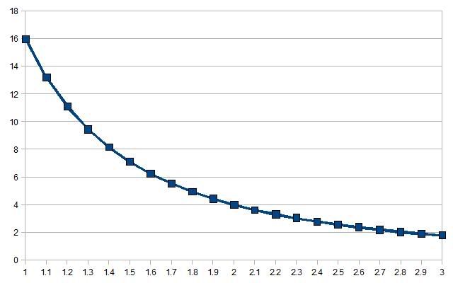
It can be shown that as one gets further from the source the signal received will decrease as shown in the graph below. The number 1 on the X axis represents concentric arrangement. As the centers depart from one another, the field felt decreases accordingly.

It can also be surmised that what is felt by the secondary, is returned in Lenz like fassion to the primary, constituting a feedback to the source, and equating to work done. The ratio of power induced on the secondary to power returned to source in Lenz like reactions can be considered a multiplicaiton ratio. So for example with our previous calculations, as the secondary feels 4 units, and returns to the source 1unit of detraction, the multiplication ratio is 4.
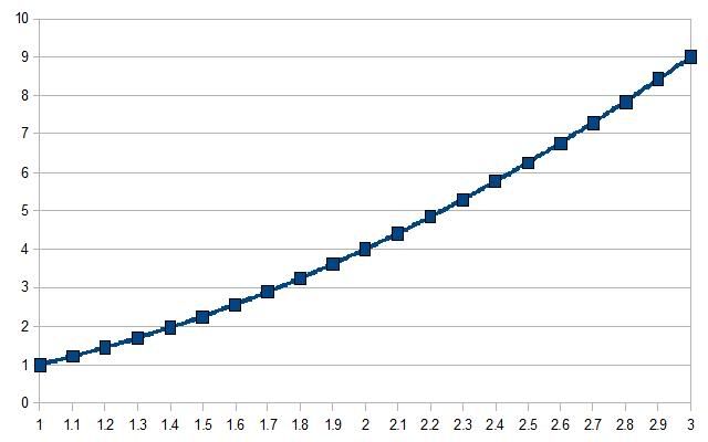
It can be seen when graphing this in the chart below, that as one moves further and further from the source, the process becomes more and more efficient. At 3r it becomes a multiplication ratio of 9, at 4r, 16 and so on.

It must be realized though that while the process becomes more and more efficient, the average power felt by the secondary decreases. We can see that the graphs have inverse relations in their slopes, and so there will be one point at which they cross. This intersection in the graphs represents the best possible agreement between power felt by the secondary, and the calculated multiplication factor. Mathematically the two equations can be set to one another used to derive the graphs, and find a common solution.
Thanks for viewing
Andrew Manrique
Inductive Transformer action
The standard transformer According to Faraday's law (put in this convenient permutation)
Voltage Generated = (-N)(delta (BA))/delta t)
Where we have replaced the unit of inductance with its terms:
-N = number of turns
B = Magnetic field strength in Tesla
A = Area of turns
Assuming the primary and secondary are concentric (about the same center) Lenz law applies in the standard way, giving us an equal and opposite EMF equating to equal and opposite energy states on both primary and secondary minus losses. This essentially describes the bulk of the "transformation" process mechanism for this example. It may not be readily apparent, but the Inverse Squared law of electromagnetic radiation is also in effect, though it is hidden to us in conventional designs.
According to the inverse squared law, as we increase the diameter of the secondary (around the primary, concentrically) the magnitude of the EMF created by the primary will decrease accordingly. As we get one radius away from the primary, the magnitude will be 1/4 of the source. But we have also increased area by a factor of four (area of a circle increases by factor of 4 with a doubling of the radius). Therefore in the equation for Faraday's law, the factors of 1/4 and 4 cancel out for no net effect.
This clearly shows both in practice, and mathematical convenience, that when sharing a common center, Faraday's law creates an Equal and Opposite reaction to any change with respect to time in the current of the primary. However, if the primary and secondary do NOT share centers, a new area of study becomes of interest.
If the secondary is wound about a separate center, sitting adjacent to the primary, Lenz law does not behave in the familiar way. The secondary coil will feel a fraction of the field emitted by the primary according to the inverse square law of electromagnetics. For example:
Primary coil: 16 units Field strength
Secondary coil: 2r away from centre of primary
secondary coil: “Feels”: 4 units Field strength
Because of the inverse square law, and our geometric spacing, we can see that the secondary at distance 2r will see only ¼ of the emf as if it had been wound about the same centre as the primary. The secondary will now react per Lenz law to push back on the oscillations of the primary coil. This opposing oscillation must now travel back to the primary across free space, and according to the inverse squared law once again, its magnitude will decrease. If we decrease by a factor of 4 once more, we can see that the primary coil will feel a BEMF of only 1unit. To summarize:
Primary coil:
16 units of field radiating
Secondary coil:
Feels 4 units of field from primary
Creates equal and opposite 4 units per Lenz Law (BEMF)
Primary coil:
Feels 1 unit of BEMF From secondary
So we have expended 16 units, to "create" 4, which pushes back for a total of 1. Hugely inefficient, unless you consider the primary to be a charge conserving resonant structure. In this situation, minus the average reduction due to Q loss, 16 units gets reduced by the BEMF for 1, to create 4 units. The rest of the charge within the primary is conserved and reused in succeeding cycles. Thus we find that the primary consumes 1 unit of energy (minus loss) to create 4 units of energy. Here the "equal and opposite" apparent in all areas of electromagnetics has not been circumvented in any way, simply the geometry has been changed to our advantage.
This same effect can also be calculated using only the capacitive coupling for transformer action.
Capacitors can be arranged in simple geometric ways to act as transformers much the same way inductors can. Such a transformer would appear as a sphere, with a sphere around it concentrically. Because the energy states of both “plates” of our capacitor must be equal, but, the surface area of the inner sphere is less than that of the outer sphere, it will have higher charge density than the outer sphere. The ratio of sizes of the inner sphere to the outer sphere can manipulate the charge density on each to give us transformer action in well known ratios. The mathematics are a direct derivation of
Gauss' law. Because both spheres are about the same center, you will find a situation identical to the transformer described in the previous section. When a change in potential on one sphere occurs, it is mirrored in the second sphere equal and opposite.

One may remove the concentricity aspect of this transformer, and place the spheres on eccentric centers. Here one sphere will be physically next to the other. A simple mental experiment will show that we are left with a similar situation to the transformer action described above. We will assume once again that the primary sphere emits a field of 16 units and both spheres have equal capacitance. The second capacitor sitting 2r away will feel only 4 units of potential with respect to ground, once again due to the inverse squared law of electromagnetics. The secondary capacitor is allowed to charge to this 4 unit potential. In practice the primary sphere will be attached to an inductor which allows for a resonant circuit. Each cycle the sphere discharges its energy back into the inductor and it is recycled. Because our secondary is now charged, and emitting its own field of 4 units, the primary cannot discharge 100% of its energy back into the inductor. The secondary per inverse squared mechanics will have the primary sitting in its field and the primary will feel 1 unit of field. Now where the primary would have discharged all 16 units back into the inductor for re use, it instead only returns 15 units because one unit is held stationary by the charge found on the secondary. Once again we find ourselves expending 1 unit to create 4 total minus loss.
It can be seen in both cases that by simply changing the geometric relations of primary and secondary, energy can be created. In similar fashion, and through creative design energy can also be destroyed.
It can be shown that as one gets further from the source the signal received will decrease as shown in the graph below. The number 1 on the X axis represents concentric arrangement. As the centers depart from one another, the field felt decreases accordingly.

It can also be surmised that what is felt by the secondary, is returned in Lenz like fassion to the primary, constituting a feedback to the source, and equating to work done. The ratio of power induced on the secondary to power returned to source in Lenz like reactions can be considered a multiplicaiton ratio. So for example with our previous calculations, as the secondary feels 4 units, and returns to the source 1unit of detraction, the multiplication ratio is 4.
It can be seen when graphing this in the chart below, that as one moves further and further from the source, the process becomes more and more efficient. At 3r it becomes a multiplication ratio of 9, at 4r, 16 and so on.

It must be realized though that while the process becomes more and more efficient, the average power felt by the secondary decreases. We can see that the graphs have inverse relations in their slopes, and so there will be one point at which they cross. This intersection in the graphs represents the best possible agreement between power felt by the secondary, and the calculated multiplication factor. Mathematically the two equations can be set to one another used to derive the graphs, and find a common solution.
Thanks for viewing
Andrew Manrique


Comment