Announcement

Collapse
No announcement yet.

Self running coil?

Collapse
X
 
  • Filter
  • Time
  • Show
Clear All
new posts

  • Hi David,

    you may want to wait a little as the more knowledgeable are recommending a mosfet that has less capacitance then the IRF640. They say that much of the energy is consumed by this high capacitance.

    So, if you want to get some now! then get the IRF510 which are a little better. They are made by International Rectifier

    Luc

    Comment


    • Thanks luc, ordering a few 640's and also some 510's and a sig gen ( a bit of shopping therapy ) , also might get that LTC 1799 chip, looks handy going up to such a high frequency.

      Comment


      • Originally posted by gotoluc View Post
        Thanks for the video link ewizard

        I think the large toroid transformer core would be a silicon steel tape core.

        If you want to replicate my effect you would need a Ferrite core which is very different in behavior than a steel core.

        Let me know what you think

        Thanks for sharing

        Luc
        Yes thanks for that info as I had no idea what's in the center except it's magnetic as a Neo is strongly attracted to it. If I can't think of another use for it I may strip the existing wire off to see but you are probably right. I'll be winding some of the other torroids I've got that I believe may be ferrite (although some may be iron).
        Are iron torroids typically coated and ferrite uncoated?

        I've also had an idea that winding a torroid on a plastic or completely non-metallic core may be an idea worth pursuing for experiments like this. What do you think?
        There is no important work, there are only a series of moments to demonstrate your mastery and impeccability. Quote from Almine

        Comment


        • Originally posted by ewizard View Post
          Yes thanks for that info as I had no idea what's in the center except it's magnetic as a Neo is strongly attracted to it. If I can't think of another use for it I may strip the existing wire off to see but you are probably right. I'll be winding some of the other torroids I've got that I believe may be ferrite (although some may be iron).
          Are iron torroids typically coated and ferrite uncoated?

          I've also had an idea that winding a torroid on a plastic or completely non-metallic core may be an idea worth pursuing for experiments like this. What do you think?
          Yes ewizard, many steel toroids are painted. Steel or iron don't do the same thing as ferrite. The best way to test them is attached an inductance meter to the coil and bring a magnet to the core. If the inductance drops it's a ferrite if no change then it's steel and I don't think these are suitable for this effect.

          Ferrite is usually a charcoal black gray color and most often not coated.

          Luc

          Comment


          • That is what I thought - I've known ferrite cores for a long time but didn't know if they were coating them now. Wouldn't really make sense since I don't think they will rust whereas bare iron or steel will rust if not coated.
            Thanks again for that info.
            Darn I accidentally deleted some scope shots I was going to put up. Using only one probe I was having what looked like 2 patterns similar to what you had in the video #11 where there were basically 2 more or less square wave patterns offset 180 degrees from each other. Still haven't had time to wind a proper torroid but I'm going to try the newly arrived IRF640's asap.
            There is no important work, there are only a series of moments to demonstrate your mastery and impeccability. Quote from Almine

            Comment


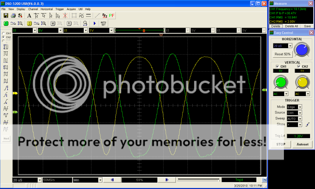
            • Hi everyone,

              I have an update video: YouTube - Self Running Coil test 13

              Scope shot is from video test.

              Luc

              Comment


              • That's an very neat find getting the mosfet to oscillate by itself! I wasn't too clear in the vid if you were able to disconnect the battery and run of the Caps. Is that still possible and will they hold at a voltage level or increase?

                I was finally able to get some time to try the new IRF640's I had but am still using coils with what is probably very low inductance (small amount of turns) since I haven't wound my own yet. However I was getting some interesting results but at much higher frequencies - from around 400 KHz and some other points up around 900 Khz and even close to 3 Mhz. Some very narrow points where voltage would increase a lot and was very much affected by the magnet and position of it. No magnet meant a lot lower voltage. I didn't document much but had a number of unusual things. I should have had camera for some of the scope shots but didn't have one ready at the time. I also think one of the 5 mosfets I ordered has bit the dust already - so much for cheap ones. I probably need to see if I've got any of those SK2806-01's in anything around here. Do you know where it came from?
                I've been looking at the newer info on the L. Tseung thread on OU that deals with using magnets in a cut out section of a transformer and using resonance to achieve OU. I think between your circuit and that concept there may be some ways of putting both together in a way that may achieve some interesting results. It wasn't until a couple days ago that I found what I consider useful info in that message thread.
                Thanks again for another well done informative video.
                There is no important work, there are only a series of moments to demonstrate your mastery and impeccability. Quote from Almine

                Comment


                • Originally posted by ewizard View Post
                  That's an very neat find getting the mosfet to oscillate by itself! I wasn't too clear in the vid if you were able to disconnect the battery and run of the Caps. Is that still possible and will they hold at a voltage level or increase?

                  I was finally able to get some time to try the new IRF640's I had but am still using coils with what is probably very low inductance (small amount of turns) since I haven't wound my own yet. However I was getting some interesting results but at much higher frequencies - from around 400 KHz and some other points up around 900 Khz and even close to 3 Mhz. Some very narrow points where voltage would increase a lot and was very much affected by the magnet and position of it. No magnet meant a lot lower voltage. I didn't document much but had a number of unusual things. I should have had camera for some of the scope shots but didn't have one ready at the time. I also think one of the 5 mosfets I ordered has bit the dust already - so much for cheap ones. I probably need to see if I've got any of those SK2806-01's in anything around here. Do you know where it came from?
                  I've been looking at the newer info on the L. Tseung thread on OU that deals with using magnets in a cut out section of a transformer and using resonance to achieve OU. I think between your circuit and that concept there may be some ways of putting both together in a way that may achieve some interesting results. It wasn't until a couple days ago that I found what I consider useful info in that message thread.
                  Thanks again for another well done informative video.
                  Hi ewizard,

                  no! the circuit only self switches at this time, meaning no external energy is used for the switch as it uses its own. The lowest current use so far (when creating its own switching energy) is around 46 micro amps.

                  I think it could get better but it maybe small increments at the time from here.

                  I salvaged the SK2806-01 over a year ago from a PC power supply or a CRT monitor.

                  I'm going to buy another MOSFET that may use even less energy to switch.

                  I'll post the link once I buy it.

                  Luc

                  Comment


                  • Self running coil.

                    @Luc,

                    You're self running switch is a work of sheer genius! I am really excited about the possibility that you can succeed once again at getting the other side of the circuit to replicate it's prior performance. These two accomplishments together at this point are really intoxicating to witness. Thanks for thrilling us so deeply! Can't wait for your creation to come completely to life.

                    Comment


                    • LUC,

                      attached is a circuit i just put together and seems to work nicely, taking the feed from my function generator ( did i mention that i had a new function generator? )...to an opto 4N25, then to a MOSFET.

                      i have the function generator ( did i mention that i now have a brand new function generator btw? ) set to square wave obv' and voltage output just enough to trigger the diode of the opto ( around 3 volts or so )

                      btw, did i mention that i now have a nice new function generator?

                      hope this comes in handy

                      David. D
                      p.s just tested, the opto seems to hold a very good square wave shape up to around 35KHz or so...after that...it gets more and more rounded till it breaks down into almost an AC wave.

                      p.p.s LUC, if you decide to use more thqn 12V supply, then you will have to put in a voltage divider with resistors between the + and pin 5 of the opto so that the opto sees only 12 V or so. Either that, or you can have a seprate 12V supply feeding the transistor side of the opto.....and a seperate supply connected across the mosfet ./all with a common ground of course.
                      Attached Files
                      Last edited by rave154; 03-27-2010, 07:33 PM.

                      Comment


                      • Hi luc,
                        First off, genious resonator! Thanks for trying the cap. Ive run some math to help maybe. Im not sure what your inductance in the last test is but im assuming its 200mH. If thats the case than with the 0.002uf capacitor, the resonant frequancy of the coil should be 7957 Hz. I find it odd that the calculated frequency of your coil is so far off from the frequency that you have been using I wonder if the coils special winding plays a role in that. Either way this may suggest that the tuning can get better. You should be able to tune the frequency by putting a potentiometer in series with your oscilating inductor or using a magnet to tune that core. But i might be wrong, its such a new oscilator, im still trying to wrap my brain around it. I have figured out where some of your losses have come from by adding the capacitor. In the tank circuit you now have introduced a circulating current, this current is much larger than the current you are putting into the tank. We can use ohms law to determin the current.

                        V=10.94V rms
                        R=6.7 ohms (coil resistance)
                        I=V/R
                        I=10.94/6.7

                        I=1.63 amps

                        Your at a low enough frequency that we dont have to worry about skin effect but your 30 awg wire is not capable of pushing 1.63A. Maximum amps for power transmission of 30 awg is 0.142A. So your wasting energy in heat. We can easily correct that be changing the value of the voltage. We can use ohms law again to calculate the maximum voltage you can use in that particular setup.

                        I=0.142A
                        R=6.7(coil resistance)
                        V=IR
                        V=0.142(6.7)

                        V=0.95 volts

                        If you take a temperature reading of your current setup running off 12V you should find that the coil is heating up, and dont forget the capacitor too. It must be able to withstand the amperage as well. If it heats up you can use multiple caps in parallel of lesser value to add up to the desired capacitance and give a higher amp capability. And all wires between coil and cap must be able to handle the power as well. So if you are pushing your toroid over 0.95 volts, than you are wasting energy in heat. Please correct me if i have something wrong here.

                        Comment


                        • Originally posted by synchro View Post
                          @Luc,

                          You're self running switch is a work of sheer genius! I am really excited about the possibility that you can succeed once again at getting the other side of the circuit to replicate it's prior performance. These two accomplishments together at this point are really intoxicating to witness. Thanks for thrilling us so deeply! Can't wait for your creation to come completely to life.
                          Thanks synchro for your interest and enthusiasm

                          I will share the self resonating mosfet switch with all even if the circuit proves not to be OU.

                          Luc

                          Comment


                          • Originally posted by rave154 View Post
                            LUC,

                            attached is a circuit i just put together and seems to work nicely, taking the feed from my function generator ( did i mention that i had a new function generator? )...to an opto 4N25, then to a MOSFET.

                            i have the function generator ( did i mention that i now have a brand new function generator btw? ) set to square wave obv' and voltage output just enough to trigger the diode of the opto ( around 3 volts or so )

                            btw, did i mention that i now have a nice new function generator?

                            hope this comes in handy

                            David. D
                            p.s just tested, the opto seems to hold a very good square wave shape up to around 35KHz or so...after that...it gets more and more rounded till it breaks down into almost an AC wave.

                            p.p.s LUC, if you decide to use more thqn 12V supply, then you will have to put in a voltage divider with resistors between the + and pin 5 of the opto so that the opto sees only 12 V or so. Either that, or you can have a seprate 12V supply feeding the transistor side of the opto.....and a seperate supply connected across the mosfet ./all with a common ground of course.
                            Hi David,... I guess a congratulations is in order for your new purchase of signal generator

                            Thanks for testing the OPTO and providing the circuit

                            Can you place a current shunt to measure the current used by the switching side. Then replace the 1K resistor between source and gate with a 10K and re-measure to see if a higher resistance helps to lower current.

                            Thanks for your time and sharing

                            BTW did I say congratulations on your Generator purchase

                            Luc

                            Comment


                            • Shouldn't the driven coil be a toroid too?
                              No one has used the dual waveform clipper like on page 103 of the Radio Shack book to make it self-oscilator like I did on my TPU?
                              mark

                              Comment


                              • Originally posted by cody View Post
                                Hi luc,
                                First off, genious resonator! Thanks for trying the cap. Ive run some math to help maybe. Im not sure what your inductance in the last test is but im assuming its 200mH. If thats the case than with the 0.002uf capacitor, the resonant frequancy of the coil should be 7957 Hz. I find it odd that the calculated frequency of your coil is so far off from the frequency that you have been using I wonder if the coils special winding plays a role in that. Either way this may suggest that the tuning can get better. You should be able to tune the frequency by putting a potentiometer in series with your oscilating inductor or using a magnet to tune that core. But i might be wrong, its such a new oscilator, im still trying to wrap my brain around it. I have figured out where some of your losses have come from by adding the capacitor. In the tank circuit you now have introduced a circulating current, this current is much larger than the current you are putting into the tank. We can use ohms law to determin the current.

                                V=10.94V rms
                                R=6.7 ohms (coil resistance)
                                I=V/R
                                I=10.94/6.7

                                I=1.63 amps

                                Your at a low enough frequency that we dont have to worry about skin effect but your 30 awg wire is not capable of pushing 1.63A. Maximum amps for power transmission of 30 awg is 0.142A. So your wasting energy in heat. We can easily correct that be changing the value of the voltage. We can use ohms law again to calculate the maximum voltage you can use in that particular setup.

                                I=0.142A
                                R=6.7(coil resistance)
                                V=IR
                                V=0.142(6.7)

                                V=0.95 volts

                                If you take a temperature reading of your current setup running off 12V you should find that the coil is heating up, and dont forget the capacitor too. It must be able to withstand the amperage as well. If it heats up you can use multiple caps in parallel of lesser value to add up to the desired capacitance and give a higher amp capability. And all wires between coil and cap must be able to handle the power as well. So if you are pushing your toroid over 0.95 volts, than you are wasting energy in heat. Please correct me if i have something wrong here.
                                Hi Cody.

                                thanks for your interest and help also

                                The inductance of the toroid coil (with magnets and air gap) in test 13 video is around 26mH + - 1mH

                                As for the oscillation inductor connected between gate and source. After a full day of playing with this, it seems there is no need for a resistor and the resistance of the inductor does not seem to matter. It's all about Inductance

                                At this time I'm playing with the circuit and will give you the details of the toroid coils. I say coils because I wound a quick one layer toroid as the mosfet pulse inductor.

                                The mosfet is a 2SK2806-01
                                Battery voltage is 12.88vdc
                                Main Toroid is 6.95 Ohms DC
                                Its Inductance is 117mH (with magnets)
                                Pulse Toroid is 0.097 Ohms DC
                                Its Inductance is 19mH

                                So using the 2SK2806-01 mosfet which needs min. 2v to trigger the above Pulse inductor specs will do it as long as the input voltage is 12.88vdc and the the main pulse coil inductance is 117mH. The result of this combination will be a sine wave Resonance at 14KHz.

                                Lower the main coil inductance and you will need to also lower the pulse inductor and the result will be a higher Resonance frequency.

                                Maybe a formula could be established that one could just input mosfet minimum gate trigger voltage, main coil inductance and source voltage, then it would give you the pulse coil inductance needed and also tell you the resonating frequency. I think this would be possible.

                                There is no need for the pulse inductor coil to be a toroid. I used one to see if I can find any advantages and see if less resistance used less power. So far I can't see any advantages.

                                Cody, can you please look this over and recommend the best voltage and frequency I should be using and I could re-tune to see if I can find any advantages. So far the lowest I could get the current down just before the circuit stops pulsing because of not enough pulse voltage produced (at gate) is 30uA @ 12.88vdc. The frequency range I tested is 30KHz down to 14KHz and all are about the same 30uA results.

                                Thanks for your help and time.

                                Luc

                                ADDED

                                Link to MOSFET pdf: skory.gylcomp.hu/alkatresz/2sk2806.pdf
                                Last edited by gotoluc; 03-27-2010, 09:57 PM.

                                Comment

                                Working...
                                X