Announcement

Collapse
No announcement yet.

Self running coil?

Collapse
X
 
  • Filter
  • Time
  • Show
Clear All
new posts

  • Self running coil?

    Hi everyone,

    I have a new effect involving a ferrite toroid coil which is being pulsed at a very specific frequency, duty cycle and uses a permanent magnet with an air gap.

    It seems to be self running once started and the source battery can be disconnected and the capacitor will maintain its charge and in fact gain energy.

    I found this effect over a week ago and since then in my spare time have been trying to find what I could be overlooking. So far I have not found anything, so I invite anyone to comment as to what I may of missed.

    The video demo: YouTube - Self Running Coil test 1

    If the magnet is removed there is no effect

    If the magnet has no air gap there is no effect

    If the frequency is changed there is no effect

    If I leave the battery connected it does not drain in voltage and actually seems to be charging the battery.

    I have changed the mosfet with the same IRF640 and it is the same. I tried it with IRF840 and it works but not quite as good as the IRF640

    The effect only seems to work at low voltage 2.80vdc is about the highest I got it to go so far.

    Please feel free to share you comments or concerns.

    Luc

    Here is the up to date circuit at this time:
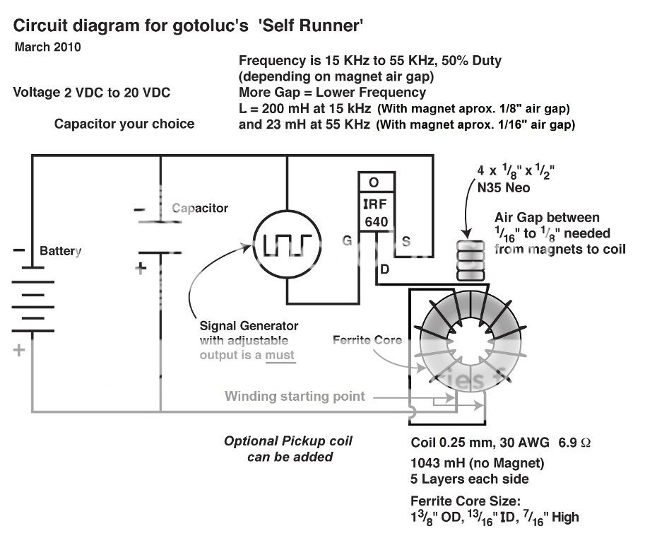
    Last edited by gotoluc; 03-19-2010, 02:54 PM.

  • #2
    Great work LUC ( as usual ! )

    My first thought, do you have any high-turn precision pots .. mine are 20 turn or 22 turn, i used them on the pwm circuit when we were doing the Re-cycling the BEMF circuit,

    basically i found the rough area i was was looking for in terms of resistance.. [ which you already have found]...i then measured what the value of the crude pot was...subtracted a little from this value and made up a resistance of this value using normal resistors plus my precision pot which then enabled me to "scan" through the range with more precision until i found the area i was looking for.

    in fact, once the precision pot is in place, it would be interesting to see a sort of graph of duty cycle (x axis ) versus voltage on cap (y axis ) for different values around the "peak" you appear to have found. There may well be a "spot" in there that has an even higher value once it is found.

    So basically, if indeed you havent missed anything ( which it appears you havent )...a pulse taken from the cap is being fed into the coil... and the returning "whatever it is" is greater than what was taken out thus the cap voltage increases..its also interesting that the cap voltage went up when the battery was removed...looks like the battery was acting to hold the whole back rather than helping.

    oh, one last thought, as you stated in the video, when you adjust the duty cycle the freq' also changes and vice versa...so with that in mind, the effect may be sensitive to one or other of those parameters or indeed both...

    as a quicky test to try and determine which factor ( duty or freq ) the effect is sensitive to... could you setup your system using the same duty cycle as you had in the video..but using a fairly different freq...say.15Khz...

    then.. reverse.....setup using the same freq as the first video ( 18Khz...but using a very much different duty cycle..say...10% or something )

    both os these tests ( if you havent already tried them ) should give a good indication of which factor the effect is senstive to.

    one last thought, could some current coming from the 555 into the GATE of the mosfet be beinf fed into the coil also thus helping to create whats going on?....to test for this.... replace the 12V battery that was feeding the 555 circuit...and try a 6V ( which the 555 should happily run on ) or a 9V.

    Great Stuff

    Comment


    • #3
      LUC, im posting this here, because A) i think youll find it fascinating ..and B) its pretty much all about a toroid...


      http://www.energeticforum.com/attach...sfluxan-2-.pdf

      Comment


      • #4
        similar effect to STEAP

        Hi Luc

        Nice video as always. This is very similar to my STEAP set up. Try taking away the cap and connect a coil and cap in series instead. The cap should be around .33mf, also put a blocking diode on your negative feed from the PWM to the coil so as once you have it tuned up, the LC circuit will go into self oscillation.

        Now if this works you could replace the pwm with a coil and reed sw setup where the coil is driven from the BEMF and you may then have your self runner. This is what I did, and the duty and frequency is critical. The thing that changes in your set up to mine is the magnets, interesting, I will have to try that!

        Mike

        Comment


        • #5
          Some time ago I found a similar setup on the site of Jean-Louis Naudin (2SGen, an amazing tiny Solid State Generator by JL Naudin) He’s been experimenting with Neodymium magnets and a similar coil as to what you have. He did not have the gap between the magnet and the coil though. How exactly did you do the windings on the coil?
          Best regards,
          B

          Comment


          • #6
            IMHO you are producing radiant energy. Maybe you should check if a additional coil around magnet or nearby toroid gives any voltage.
            Simple answer - you are getting energy from or using permanent magnet, I think all will agree. Ha ha ha ! They said it can't be done !

            Comment


            • #7
              Hi all,

              thanks for your interest.

              I made a new video to help with questions or doubts since I know it is had to believe that you can pulse a coil and more energy seems to be coming back. It took me over a week of testing different things after I found this effect to try to find what I could be overlooking but came up with nothing yet.

              Video: YouTube - Self Running Coil test 2

              Luc
              Last edited by gotoluc; 03-13-2010, 07:32 PM.

              Comment


              • #8
                LUC......Namaste for your efforts, seriously !

                the only possible "thing" i can think of.........is that a current is seeping through the gate of the mosfet into the coil.......somehow ( remember, im not the electronics wizzkid here by any means ).....other than that......im kinda gettin goose bumps at what youve stumbled on.

                ty, for doing the 9V battery swap btw.

                damn ive got like a thousand thoughts going on right now

                ok, how about this...... FWBR coming off the toroid, to a cap, to collect the BEMF ( flyback) from the pulses......to power.....an LED ( bulb? )


                since the coil is effectively running "for nothing"...... why not collect the flyback and power a load. of course while im typing all of this....what im really leading up to is...... some way......to take whats coming out......and feed it back in......the only problem is that the 555 takes minimum of 5V to run....even the CMOS version of it takes the same i belive although it runs on a lot less amps.

                LUC......while youve got the circuit running as it is....... have you played around with other magnets......wafting them on or around the toroid as the circuit is running and observing changes in cap voltage?

                p.s did you read the PDF i posted,,,,,,its a real revelation in terms of "transformer action"....it really put into place some of the questions i had in terms of......"why does 1 turn on the 2ndary = 1 volt"......etc , a real eye opener.

                keep going man

                Ahimsa to you

                David. D

                Comment


                • #9
                  Ah,if you could show us magnetic field around working toroid with and without neo magnets ! Optocoupler would be also best to check leaking current through gate.

                  Comment


                  • #10
                    Originally posted by rave154 View Post
                    LUC......Namaste for your efforts, seriously !

                    the only possible "thing" i can think of.........is that a current is seeping through the gate of the mosfet into the coil.......somehow ( remember, im not the electronics wizzkid here by any means ).....other than that......im kinda gettin goose bumps at what youve stumbled on.

                    ty, for doing the 9V battery swap btw.

                    damn ive got like a thousand thoughts going on right now

                    ok, how about this...... FWBR coming off the toroid, to a cap, to collect the BEMF ( flyback) from the pulses......to power.....an LED ( bulb? )


                    since the coil is effectively running "for nothing"...... why not collect the flyback and power a load. of course while im typing all of this....what im really leading up to is...... some way......to take whats coming out......and feed it back in......the only problem is that the 555 takes minimum of 5V to run....even the CMOS version of it takes the same i belive although it runs on a lot less amps.

                    LUC......while youve got the circuit running as it is....... have you played around with other magnets......wafting them on or around the toroid as the circuit is running and observing changes in cap voltage?

                    p.s did you read the PDF i posted,,,,,,its a real revelation in terms of "transformer action"....it really put into place some of the questions i had in terms of......"why does 1 turn on the 2ndary = 1 volt"......etc , a real eye opener.

                    keep going man

                    Ahimsa to you

                    David. D
                    Hi David,

                    thanks for your pdf and support.

                    I believe when the Toroids magnet and pulse Frequency perimeters are all set right the Toroid coil goes into Resonance. Since connecting my probe or bringing any ferromagnetic material close by the Toroid has a negative effect (becomes un-tuned).

                    I tried collecting Flyback and it is possible, however when I do the math it all comes to the same. What I mean is the flyback energy you collect is that much less going back to the source capacitor.

                    I made a new video to further explain the the importance of the Frequency, Duty Cycle and mostly the Permanent magnet that without it there is no Frequency that will create this effect.


                    If we think about it ... I only remove the magnet from the toroid coil and it starts to use current, so how can the energy that was going back to the source of been coming from the MOSFET gate pulse and now suddenly stop

                    New video: YouTube - Self Running Coil test 3

                    Luc
                    Last edited by gotoluc; 03-13-2010, 09:27 PM.

                    Comment


                    • #11
                      Nice work on this gotoluc I've been thinking along these lines lately also if I could only get the time - I may have to make time to try this one.

                      Lots of voltage doubler circuits out there if you decide to try for a complete self runner - which of course would then eliminate any need to isolate the 555 circuit. You would just need a brief battery kick start to get things going (at least we can all hope) Maybe this one would work:

                      Making the DC-DC Converter
                      The following parts are necessary to make this 0.7 to 5 Volt DC boost converter together with leads and either prototyping breadboard or soldering equipment and a board:

                      1 x MAX756
                      2 x 100uF Capacitors
                      2 x 0.1uF Capactitors
                      1 x 1N5817 Schottky Diode
                      1 x 22uH Power Inductor

                      The MAX756 is available direct from MAXIM with prices ranging from $3.02 (ordering 1-24) down to $1.95 (ordering 1000+). We can supply the rest of the components through the REUK Shop if required - email us to request a quote listing the components and quantities you require.

                      Circuit Diagram below

                      The circuit was tested using two 'flat' AA rechargeable batteries. The total voltage of the batteries was measured at 2.21 Volts, and the output voltage from the circuit was measured at exactly 5.00 Volts with a digital multimeter. The output voltage was used to power an ultrabright LED for 24 hours (through a 270 Ohm current limiting resistor) without any sign of dimming during that time.
                      The above is from :
                      DC Voltage Multiplier Circuit Plans - Electric Circuit
                      Attached Files
                      Last edited by ewizard; 03-13-2010, 10:04 PM.
                      There is no important work, there are only a series of moments to demonstrate your mastery and impeccability. Quote from Almine

                      Comment


                      • #12
                        Hi all,

                        Gyula has posted this explanation at the OU topic as the probable cause of the effect.

                        Hi Luc,

                        Thanks for your explanations in the second video.

                        Now my understanding on your circuit is that the MOSFET output capacitance (CDS and the 44.6mH toroidal coil forms a parallel resonant circuit at 18.8kHz. How?
                        See the data sheet for your IRF640: http://www.irf.com/product-info/data...ta/irf640n.pdf

                        See Fig. 5 in Page 4, and the output capacitance curve, Coss, shows about 1500-1600pF at 1V drain-source voltage (taken at VGS=0V).
                        And if you calculate the C value from the 18.8kHz resonant frequency using the 44.6mH toroid coil value, you get 1.61nF capacitor value! (I used this online calculator: LC Resonance Frequency Calculator at WhatCircuits.com )

                        This explains why the distance of the magnets from the core is so precisely needed to adjust: you simply change and fine tune the toroidal inductance for the best value for getting the highest output voltage which can occur at the highest impedance a parallel LC circuit provides. No resonance=no max output. The drastic change in the output capacitance also explains why you find the "effect" works at no higher than 2.8V DC: the capacitance gets reduced under the 1000pF values and the LC circuit impedance becomes lower and lower. You seem to nicely finetune the output circuit for most favorable match of the components that ensures the highest possible output.

                        The battery surely limits the rising of the capacitor voltage and there must be some charging current also flowing into the battery from the cap.

                        The phenomena of your needing to place the battery back into the circuit to get the "effect" again (after that the cap was fully discharged) is explained by also the 'wrong' value of the output capacitance at zero drain-source value: it simply much higher than 1.6nF and the battery voltage brings it within range. (Just check your unused IRF640 drain source output capacitance in itself, not connected anywhere but to a C meter if you have one, first short circuit the gate-source pins with a piece of wire to really switch it off because the higher than 1nF gate-source input cap likes to store voltage for a longer time.)

                        There remains to explain your flat current trace during the ON time of the FET but unfortunately I cannot give a correct explanation yet. One possibility:
                        I think the mistery "flat current" trace of mainly zero value is not really zero but its average value is much smaller than for instance in the case of the 10 Ohm resistor. Because the FET switched output resistance looks like to be higher than 10 Ohm due to the low duty cycle drive it receives at the gate-source input. I know this does not fully explain it though, will be thinking on it. And others here are kindly invited to share their thoughts.

                        rgds, Gyula

                        Comment


                        • #13
                          Just to share what I saw in your 3rd video as I was also following at OU here's a point I think may be important - quote from what I posted @ OU:

                          Luc, the point at which the caps started going negative in voltage after the coil was disconnected and the caps were quickly drained with the 10 Ohm resistor and before the 1.2 volt battery was put back on -- I take that as a good sign - as the coil was hooked back up at that point and since the only power in the circuit could be coming from the timer circuit and it was actually reversing the charge - it seems that may be important to note since if they were charging in a positive way then you might have to consider the voltage was leaking through from the timer circuit. I think (may be way off here) that would indicate the timer circuit/and or Mosfet is NOT leaking voltage into the caps. And that's great news!
                          Last edited by ewizard; 03-14-2010, 12:36 AM.
                          There is no important work, there are only a series of moments to demonstrate your mastery and impeccability. Quote from Almine

                          Comment


                          • #14
                            Hi Luc,

                            Ok on your posting my answer here but let me add the rest I wrote some minutes later, to complete my explanation:

                            Hi Luc,

                            Just watched your 3rd video and now I think I know why you have a flat current line during the FET on-time.
                            It is explained by the resonant circuit high impedance: THERE IS current but very much less than say in the case of the 10 Ohm resistor.
                            And when you drastically detune the LC circuit from 18.8 or so kHz, by removing the magnet, the high impedance immediately gets reduced and current is taken from the capacitor (or from the battery if it is connected).

                            rgds, Gyula

                            Comment


                            • #15
                              I'm still fairly lost in much of this as it's been so long since I've built circuits. I'm trying to understand what Gyula said in what is actually limiting voltage to around 2.8 volts. What would you say is the actual limiting part or concept that limits it to that voltage? Coil size? Mosfet? Or?
                              BTW can you post the schematic of just the coil circuit and part specs beyond the IRF640? I think I may have everything except I'm not sure what the small cap is in the breadboard by the Mosfet. I think since I've got a digital signal generator I wouldn't need the timer circuit although if this all works out it would be incredible to have it all running from it's own power. Thanks for any help with this.
                              edit: Ahhh I see Gyula is here now - thanks for your expertise in this also - your understanding is way ahead of mine in this.
                              Last edited by ewizard; 03-13-2010, 11:26 PM.
                              There is no important work, there are only a series of moments to demonstrate your mastery and impeccability. Quote from Almine

                              Comment

                              Working...
                              X