Announcement

Collapse
No announcement yet.

Self running coil?

Collapse
X
 
  • Filter
  • Time
  • Show
Clear All
new posts

  • #61
    getting close

    Hey Luc,

    That's looking good vids 5 & 6 great (as usual). In Vid #5, you might note that even though you see a voltage spike, it may mean very little because these are Mosfets. What we need to know is what kind of current is flowing because usually driver current is represented in uA. That's what's nice about MOSFETS is that they are charge (field) controlled devices. Because there is capacitance at a MOSFET gate, the driver circuit ends up with the task of sinking power required to present a 'crisp' switching charge at the gate.

    So what we need to do is to monitor the gate power dissipated by the driver (pulse generator) at the gate and compare that power to the power charging you cap(s). Then tune accordingly.

    I found this pdf on Mosfets and it's pretty good:

    http://02d1852.netsolhost.com/plasma/mosfet.pdf

    Greg
    Last edited by gmeast; 03-18-2010, 03:17 PM.

    Comment


    • #62
      Originally posted by gmeast View Post
      Hey Luc,

      That's looking good vids 5 & 6 great (as usual). In Vid #5, you might note that even though you see a voltage spike, it may mean very little because these are Mosfets. What we need to know is what kind of current is flowing because usually driver current is represented in uA. That's what's nice about MOSFETS is that they are charge controlled devices. Because there is capacitance at a MOSFET gate, the driver circuit ends up with the task of sinking power required to present a 'crisp' switching charge at the gate.

      So what we need to do is to monitor the gate power dissipated by the driver (pulse generator) at the gate and compare that power to the power charging you cap(s). Then tune accordingly.

      I found this pdf on Mosfets and it's pretty good:

      http://02d1852.netsolhost.com/plasma/mosfet.pdf

      Greg
      Hi Greg,

      I agree, I'll try to measure the generator feed current across a 10 Ohm resistor using my scope and post the scope shot.

      Please also look at my posts at the OU topic as it contains much important information. Link: Self running coil?

      Here is a new schematic that was made by OU user: HarryV

      It is being edited as each windings need to both start on the same side of the core and not opposed sides as shown. This could be the key to making this work!!!... as I have another coil which is wound standard and I can't get it to work no mater what I try.

      Luc
      Last edited by gotoluc; 03-18-2010, 03:57 AM.

      Comment


      • #63
        Just some other info I stumbled across that may be important as it was from a fairly obscure source. It was stated in such circuits as this that if it can be made to run above 20 Khz that by adding an Earth ground in the circuit you may find your amperage increases substantially. I see you are now running well above 20 Khz so maybe this will be worth a try if you haven't already. Thanks for the schematic and I just popped back in here a minute ago so I haven't seen the new vid's yet but thanks for those too as I'll be on them in a minute
        There is no important work, there are only a series of moments to demonstrate your mastery and impeccability. Quote from Almine

        Comment


        • #64
          LUC,

          2 more great vids

          thanks a lot for taking time to do those.

          I kind of agree that it may well be that the winding of your coil is having an effect here ( along with all the other factors ) since in my setup using a "standard" toroid..i can kind of see the "peaks" that your talking about which in your setup enable you to get the minus current on the meter...which i cannot get on mine..

          if you can find time, maybe in your next vid or whatever, could you explain 'exactly' the orientation of the windings..and which end is where etc...i happen to have found a toroid that is exactly the same dimension as yours ( from a PS )..and have the same wire as you... i will wind it to your exact specifications as soon as i know precisely how its wound. A sort of kneedle & thread demo of how its wound, so to speak, so theres no ambiguity.

          Thanks again for your fantastic efforts

          David. D

          Comment


          • #65
            Originally posted by gotoluc View Post
            @Gyula, can you please explain how the 3vpp measured gate leak between the source and drain is capable of keeping the circuit running NOW at 30vdc, 57KHz with 50% duty cycle without using any current and maintaining 1.90vdc on the pickup coil with 49,850 Ohm load. Thank you for your help and time

            Test 5 video: YouTube - Self Running Coil test 5

            Test 6 video: YouTube - Self Running Coil test 6

            Luc
            Hi Luc,

            Here is my answer, written last late night, copied from Stefan's forum:

            The drain source channel of the MOSFET is practically a short circuit for the ON time (actually the RDS value of the IRF640, data sheet), the ON time now means half wave duration (earlier you used 18-20% or so duty cycle, this meant less ON time, more OFF time).

            The drain source channel of the MOSFET is very high resistance for the OFF time, and both the output capacitance of the MOSFET and the body diode is in parallel with the drain source, the OFF time means the other half wave duration of the full pulse time. Now the output capacitance is about a few ten to a few hundred pF only, because the drain source voltage is much higher than earlier, up to 30V.
            I still think the resonant tank LC circuit is formed by the output capacitance of the FET and from the 221mH (magnet-tuned) toroidal coil.

            The FET as a switch pumps energy into the tank circuit from your generator and you have to consider not only the 3V peak to peak voltage but the current spikes shown in your earlier videos as flat lines between the spikes.

            I think the input energy comes from these two: the 3Vpp and the spikes. The flat line between the spikes is explainable from the fact that the input is a square-wave: suddenly appears across the coil then its amplitude remains more or less constant, this means no or a very little flux change, then the square wave returns to zero, this also causes a flux change in the core again, current spike appears again.

            So to estimate the real input power to the tank somehow those current spikes should be studied, I believe these maintain the voltage in the caps.
            Resonant LC circuits have voltage 'amplification' properties, this depends on the loaded Q factor too. In you circuit this is modified a little, the normal Q times multiplier is not fully valid, due to the half wave rectification inside the tank.

            If I can, I will address some unanswered questions tomorrow.

            Thanks, Gyula

            Comment


            • #66
              The most important question now ! Is your capacitor electrolytic one ?
              I have stumbled with similar circuit few years ago but instead of self-running it was producing huge radiant energy , spreading electrostatic field around. I was scared and didn't do any further tests, but I'm quite sure that I would make it self-running using receiver coil. My coil was different however, not toroid.
              Scott MCKie PODMOD device is something we should look at.imho

              Comment


              • #67
                Originally posted by ewizard View Post
                Just some other info I stumbled across that may be important as it was from a fairly obscure source. It was stated in such circuits as this that if it can be made to run above 20 Khz that by adding an Earth ground in the circuit you may find your amperage increases substantially. I see you are now running well above 20 Khz so maybe this will be worth a try if you haven't already. Thanks for the schematic and I just popped back in here a minute ago so I haven't seen the new vid's yet but thanks for those too as I'll be on them in a minute
                Thanks for the suggestion ewizard, It was not tested yet to Earth ground. I will add it to the list of thing to test.

                If you don't see me post a result in a few days please remind me again.

                Luc

                Comment


                • #68
                  Originally posted by rave154 View Post
                  LUC,

                  2 more great vids

                  thanks a lot for taking time to do those.

                  I kind of agree that it may well be that the winding of your coil is having an effect here ( along with all the other factors ) since in my setup using a "standard" toroid..i can kind of see the "peaks" that your talking about which in your setup enable you to get the minus current on the meter...which i cannot get on mine..

                  if you can find time, maybe in your next vid or whatever, could you explain 'exactly' the orientation of the windings..and which end is where etc...i happen to have found a toroid that is exactly the same dimension as yours ( from a PS )..and have the same wire as you... i will wind it to your exact specifications as soon as i know precisely how its wound. A sort of kneedle & thread demo of how its wound, so to speak, so theres no ambiguity.

                  Thanks again for your fantastic efforts

                  David. D
                  Hi David,

                  at this time it seems to be pointing to coil geometry as I only have one coil that can give this effect, so let me look at this more closely and I'll report back with the details.

                  Luc

                  Comment


                  • #69
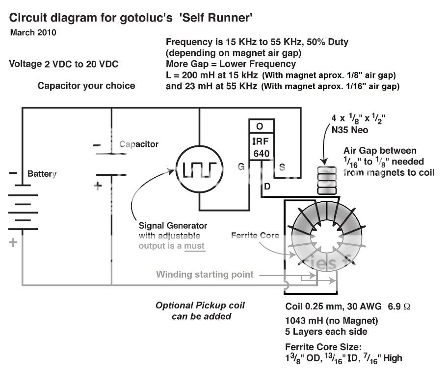
                    Here is the up to date circuit at this time.
                    Last edited by gotoluc; 03-19-2010, 03:16 AM.

                    Comment


                    • #70
                      LUC,]
                      thanks for the clear schematic ( even I can follow it lol )

                      eagerly awaiting coil winding descriptions/instructions...so i can get winding


                      p.s i have 3 of those toroid cores(from the power supplys)... 2 of which still have the original windings on....6 windings in all in all, consisting of 4 coils of fairly stout wire(maybe 1.1mm - 1.2mm)..another of about 0.8mm.and last one about 0.65mm..

                      if you have any ideas about any tests you would like me to try using those windings before i rip them off and wind the core as a replica of your own coil...feel free to ask.

                      David. D

                      Comment


                      • #71
                        LUC, just looked at OU.com....found your edited schematic with the " windings start here" on it... makes sense now..

                        looking at it...you have it wired so that the two coils are producing a field that is in the same direction....ie..... as if they are one big coil.

                        Even though one of them is wound in the opposite direction around the circumference of the toroid it is also wound opposite in terms of clockwise/counter-clockwise in relation to the other coil....and since they are wired the way you have them......it is the same as one big coil. ( i think )

                        i'll have a look at my PS toroids windings and see if i can quickly throw together a quick replica of your coil without actually re-wiring them..

                        back in a bit
                        Last edited by rave154; 03-18-2010, 04:58 PM.

                        Comment


                        • #72
                          Originally posted by rave154 View Post
                          LUC, just looked at OU.com....found your edited schematic with the " windings start here" on it... makes sense now..

                          hmm.the more i look at how the coil is wound ( & connected ) and also WHERE you have the magnet....it looks like with the coil...you have two opposing "poles"...right where the magnet is.

                          with this setup, could the flux from the magnet be being made to switch somehow..and this is whats giving the extra power?

                          i'll have a look at my PS toroids windings and see if i can quickly throw together a quick replica of your coil without actually re-wiring them..

                          back in a bit
                          Hi David,

                          I just updated the above schematic.

                          I maybe wrong but I think that Inductance value maybe important!... because when you approach the magnet Inductance starts to drop real fast so you may need a very high value to start with. Maybe that's why I can't get the other toroid to do the same effect 850mH vs 1,050mH.

                          I don't know enough yet to tell what makes this work but that's what I think at this time. So making a quick coil maybe a waste. Take your time and get it to 1,000mH or more if you can and it should work.

                          I'm going to start winding another one with a heavier wire and try to raise the Inductance also.

                          Luc

                          Comment


                          • #73
                            This was posted at the OU topic and thought it may help others here.

                            [quote author=canam101 link=topic=8892.msg233191#msg233191 date=1268931237]
                            Just looking at it from a layman's point of view, if I had such a circuit, and it looked like it was OU, the first thing I would do is to try to close the loop. If it stopped working when I tried it, it would at least get me working in a direction that would let me look at the reason for not being able to close the loop.

                            If it did close the loop, then after I got over my astonishment, I could try to find out what non-OU reason would allow me to close the loop. And it would be a hell of an incentive for everyone else to replicate what I had.

                            Either way, trying to close the loop would be very useful.

                            That may be a naive layman's view of it, but it is the reason I cannot understand why Luc doesn't even try to do this.
                            [/quote]


                            Hi canam101,

                            I personally would be surprised that the circuit (posted above) on its own would be OU

                            However, if we are able to make a Toroid with a magnet Resonate at next to no cost of energy since even the possible gate switching energy is being returned to the capacitor bank, then this is good.

                            What you and others who are not replicating may not be considering is that a pickup coil can added and real current can be extracted at no cost to the capacitor bank returned input energy.

                            This is where the possible OU or Free energy could be coming from. My tests so far show that when I add a load to the pickup coil it has no reverse effect on the input. JLN has demonstrated this also but he does not have his input at zero yet!

                            Also, there could be a possibility of multiple pickup coils added as the toroid seems to have an opposite field on each half and maybe on each side. So there could be 4 pickup coils. The other thing is the pickup coil I used is not tuned so it is not taking full advantage of the potential magnetic current.

                            Luc

                            Comment


                            • #74
                              LUC,

                              thanks again for the input, i will have a lil go with the original windings ( I will measure the inductance of them all linked up together, if its close to 1000mH then ill go further ).....as i was thinking this.....i thought of this.....see attatchment

                              both the toroids are LUC's toroids ( which essentially run for nothing )...

                              with both toroids not powered...the flux from the magnet at north pole would be absorbed by the top toroid... likewise...the south pole of the Magnet would be absorbed by the bottom toroid...

                              when both toroids are energised at the same time, the magnet reacts as if the toroids arent actually there anymore....and the flux lines would suddenly spring out in the familiar "figure-8 on its side" kind of look..as they did.they would cut the golden pickup winding at 90 degrees...and....cut them again when the toroids are de-energised.
                              Last edited by rave154; 04-23-2010, 09:27 PM.

                              Comment


                              • #75
                                RE- my last post, 2 piccys to illustrate what i meant about the flux lines
                                Last edited by rave154; 08-29-2010, 10:45 AM.

                                Comment

                                Working...
                                X