Announcement

Collapse
No announcement yet.

The Missing Fundamental Generator

Collapse
X
 
  • Filter
  • Time
  • Show
Clear All
new posts

  • #16
    Graphs for Above Spread Sheet Data

    Larger Image

    So there you have it. The sum of all Odd Harmonics produces a . . .

    How many odd harmonics can we fit in a single cycle of this type? Could each harmonic represent a single bit of information?


    "Amy Pond, there is something you need to understand, and someday your life may depend on it: I am definitely a madman with a box." ~The Doctor

    Comment


    • #17
      boyce connection?

      Doesn't Bob Boyce use the first and second subharmonic in the hex controller?

      Comment


      • #18
        ehhmmmm forget harmonics a return back to parametric oscillator
        Last edited by boguslaw; 03-08-2011, 02:23 PM.

        Comment


        • #19
          Originally posted by boguslaw View Post
          ehhmmmm forget harmonics a return back to parametric oscillator
          Forget harmonics? Why?

          I'd be happy to explain the spreadsheet if you want me to.

          Did I include the fundamental in the last graph or is it an example of a "Missing Fundamental Generator"?
          "Amy Pond, there is something you need to understand, and someday your life may depend on it: I am definitely a madman with a box." ~The Doctor

          Comment


          • #20
            Armagdn as always great thread. Instead of having that coil at 90 degrees to magnet you could spin variable capacitors out of phase with eachother so that one acts as a source and one acts as a sink. I believe that would also give you a similar excitation. I don't know if this is what you're trying to say but I thought I'd add a dielectric slant on things instead of keeping it soley magnetic

            Also Harvey, I'm not 100% sure but I think what he's saying is that by exciting the circuit parametrically we are indeed producing harmonics. Atleast that's what I made of the image accompanied by his post.

            Raui
            Scribd account; http://www.scribd.com/raui

            Comment


            • #21
              Originally posted by Harvey View Post
              Forget harmonics? Why?

              I'd be happy to explain the spreadsheet if you want me to.

              Did I include the fundamental in the last graph or is it an example of a "Missing Fundamental Generator"?
              Ok. I was wrong. I should rather said : let's find a correlation between parametric resonance and harmonics. Are harmonics a way to extract energy from external static source what happens inside parametric resonant circuit ?
              For example analyse a coil with artificially changed inductance at the correct moment. Together with capacitor such coil makes LC circuit which has a feature of accumulating energy much faster then normal resonant LC circuit (exponentially). From a paper I found I conclude that this energy is sucked from external source (static magnetic bias) somehow (I don't know how yet) and MAYBE it occur in circuit as harmonics ? But then this means that such harmonics add to the energy relocated back into capacitor (from collapsing magnetic field of variable coil) ! IMHO it's the REQUIRED way which allows accumulation of energy, because in all other situation that excess is probably radiated away as EM (radio) waves.

              Do you see something interesting ? In our nowadays LC circuits we are using semiconductor switches closing and opening LC circuit at the rate of resonant frequency, but... harmonics are FASTER then that. For me it means that when our switch open and magnetic field of coil collapse magnetic field generated by harmonic are already gone.

              What we NEED is a switch which operates at HIGHER rate ! at 2 or 4 or 8 times the resonant frequency and a very stable one.Simply to break each harmonic generated magnetic field at the peak of strength. Then each harmonic field collapse will ADD to the current generated by magnetic field collapse and stored in capacitance part of LC circuit.
              Seems like parametric resonant circuit is a natural form of more general circuits with positive feedback. On each subsequent period capacitor discharge has more energy.
              Last edited by boguslaw; 06-03-2010, 01:45 PM.

              Comment


              • #22
                @Boguslaw

                The internal bias mentioned in your post #18 attachment sounds like a magnetic amp. "Coil with artificially changed inductance" is pretty much the definition of mag amp.

                It seems to me that when Boyce takes the full wave rectified inverter output and modulates it with 42.8, 21.4 and 10.7khz harmonics in the torrid there's a whole bunch of "coil with artificially changed inductance" going on. This thing almost killed him when he didn't have it loaded with the cell.

                @ All
                So I guess my question is, is he doing something that we can learn from here?

                I'm trying to stay on topic, and not hijack this thread.

                Peace to All

                Comment


                • #23
                  Frequency and scope

                  Hi all,

                  This is just for interest, taken some time back on my STEAP circuit which is using parametric oscillation and is self running. Parametrics do work, but as of yet I have not had more time to work on this as I have been very busy on another project. Keep at this, I think it is a way forward

                  Mike
                  Last edited by Michael John Nunnerley; 11-09-2011, 03:51 PM.

                  Comment


                  • #24
                    Originally posted by Michael John Nunnerley View Post
                    Hi all,

                    This is just for interest, taken some time back on my STEAP circuit which is using parametric oscillation and is self running. Parametrics do work, but as of yet I have not had more time to work on this as I have been very busy on another project. Keep at this, I think it is a way forward

                    Mike
                    I don't see any spectacular in those screenshots. They should appear rising exponentially in time and collapsing at a high amplitude, which is not seen here.

                    Comment


                    • #25
                      interesting tests...

                      I played with a toroid with 3 coils over a primary coil each driven by it's own PWM. The frequencies were set at 144, 288 and 576. There was a few oddities that showed up in the spikes but the most interesting part was when I added an earth ground to the system. Scope shot below... It seemed to latch on a 60 hz wave. I'm not sure if it has any significance but I found it quite interesting....

                      Another experiment was with a toroid with 2 main coils 180 degrees appart with approximately 40 turns of 20 wire then between them were two coils of 5 turns,also 180 degrees appart, one shorted and the other connected to a transistor that could be pulse shorted. Going on what Andrew stated the other day about changing or altering inductance. I charged the toroid similar to Leedskalnin's PMH assuming it would charge the core with flux. Activating the transistor on and off showed there was a change in flux or at least a change in activity. The second picture shows the scope shot of that experiment. I was driving the transistor base with a FG set at 1 volt p-p and I don't know how much of that was entering the coil . That test was inconclusive as I couldn't define how much of the FG was adding to the test. Still a very nice parametric response and very interesting results.

                      It also occured to me the other day that a variable capacitor could be made similar to a speaker coil and activated by either internal or external frequencies thus giving a variable response in voltage. I haven't had time to put one together to test the idea, hopefully in the near future...

                      Fun stuff !
                      ________
                      Last edited by dragon; 11-16-2011, 01:30 AM.

                      Comment


                      • #26
                        ATTENTION Armagdn03

                        Armagdn03, check your PM.
                        Sincerely,
                        Aaron Murakami

                        Books & Videos https://emediapress.com
                        Conference http://energyscienceconference.com
                        RPX & MWO http://vril.io

                        Comment


                        • #27
                          Hello all!

                          Sorry I have not replied, there was a mix up and I was unable to post for quite a while, but now am back!

                          This topic was to illustrate how frequencies can alter one another, create beats, create changing parameters to induce other oscillations parametrically. I see no reason why anyone should not "hijack" this thread if it is relevant to this.

                          @Harvy,
                          Very nice demonstration, I will have to take a look for myself.

                          @all,
                          I think it would be very worth while to look into parameter changes in general, and here are a few thoughts that may be of use.

                          First this is an incredible patent, I think many will enjoy....please read the introductory summary.

                          Electrostatic energy generators and ... - Google Patent Search

                          second, the Steorn setup, with the toroid and also the 2Sgen are both capable Parametric style setups.

                          For example I took a toroidal inductor, measured its inductance 6.79mh.
                          Then placed a neodynium magnet against it, decreasing its inductance to 0.08 this was a 84.85 fold decrease!

                          In a generator such as "alternator having improved efficiency" by Jim Murray, he speaks of "synchronized parameter changes" same as Eric Dollard. This is because the machines to which they refer, create EMF in two ways, rate of change of parameters with respect to time, AND rate of change of magnetic field with respect to time. These must be synchronized correctly. The traditional "rate of change with respect to magnetic field" must charge the inductor or capacitor, and at just the right time, and for the correct durration, the rate of change of parameters with respect to time must decrease the parameter in question (inductance or capacitance)....however this is not always necessary, as shown in the patent described above.

                          Comment


                          • #28


                            good idea Armagdn03

                            Comment


                            • #29
                              Two articles, One for the physisists amung us, and one for the builders.


                              http://www.eqator.org/papers/reid89.pdf - Interesting read, but heavy

                              Alan Yates' Laboratory - Parametric Oscillator Experiment -

                              Practical application of parametric pumping circuits using varactors and reverse biased diodes. Interesting quote :"At half the tank resonance, there is a relatively efficient frequency doubling effect. There is a weak tripling effect at one third the resonant frequency too. This is parametric multiplication, or second and third harmonic generation. At the tank resonant frequency there is normal (but slightly distorted) resonance. At twice the tank frequency there is degenerate parametric oscillation."

                              Enjoy!

                              Comment


                              • #30
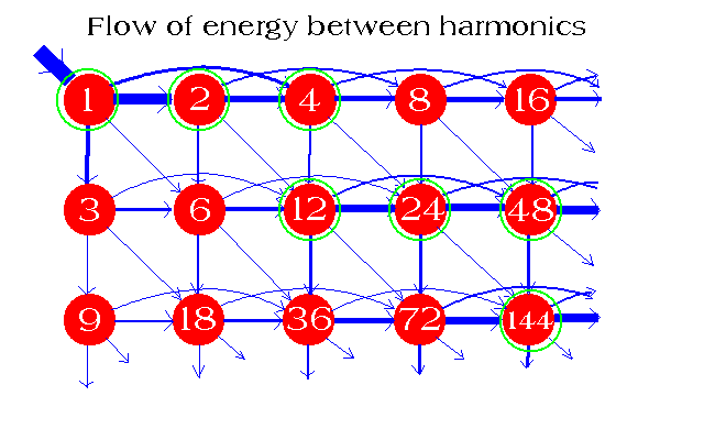
                                Originally posted by Armagdn03 View Post


                                The image above comes from an AWESOME article written by Ray Tomes and his Harmonics Theory website! Harmonics Theory Physics and Maths

                                This describes the energy flow relationship between harmonics, How do harmonics add to one another??? Subtract???

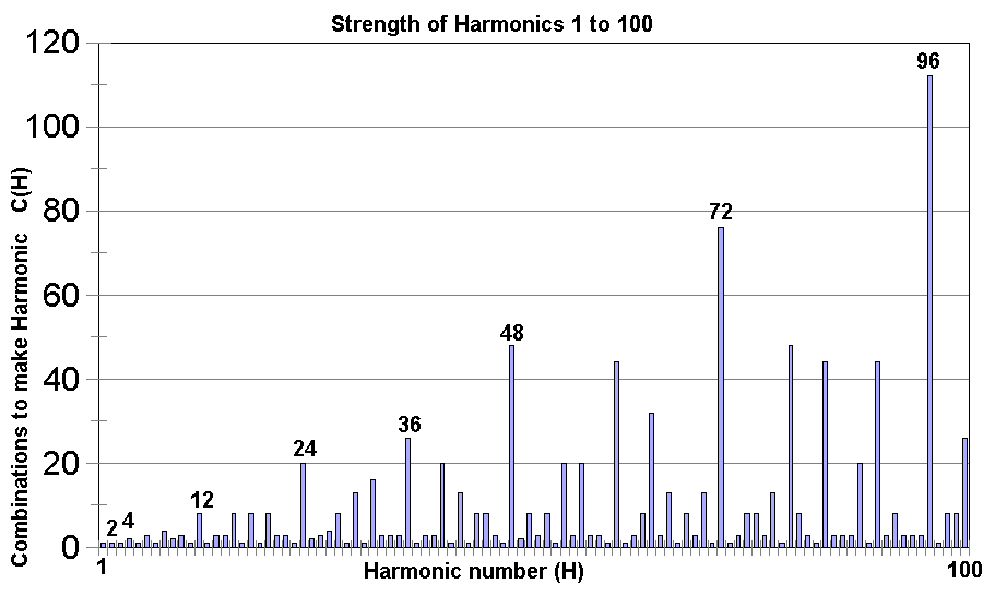
                                In the article Tomes describes different harmonic families, and begins by looking at the relative strengths of the harmonic families.


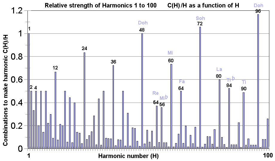
                                Here you can see that multiples of 2 and 3 are very strong and prominant harmonics, we have harmonics such as 2, 4,12,24,36 etc.

                                If we back up and take into account many more we can see a relation to music!


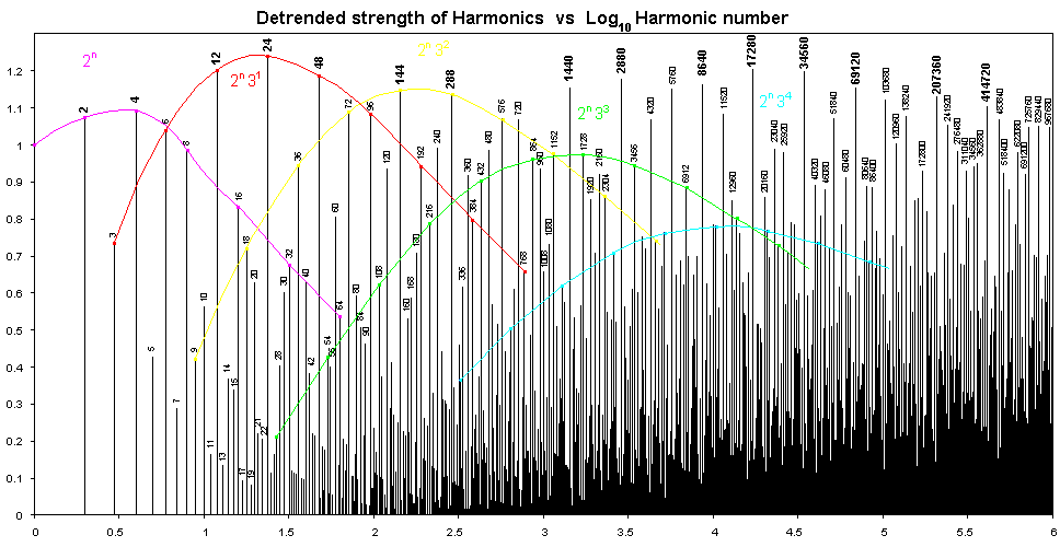
                                And we can even go further to describe the harmonic families with neat little equations!


                                How cool is this???

                                we are describing all the frequencies which can arise naturally only out of the number 1 being a fundamental frequency! We are describing how they live with each other, create each other, SUSTAIN each other!

                                We are figuring out which families are strongest! which ones will be the most prominant to appear in our apparatus as described by Dollard, and we know that when all are IN PHASE and summed within the same physical space.

                                How do we create low frequency from High, how do we create high frequency from low,

                                Answer these questions! This is what is important!
                                This IS the main part of the secret to the Steven Mark TPU. Intermodulation of 1 primary frequency with two carrier frequencies. The NEW CREATED frequencies are Harmonics of the F1. Do this in a closed loop race track, with the diameter set to the bandwidth of the harmonics, as to attract the EM wave as in a tuned magnetic loop antenna.

                                The three frequencies are as follows: Oh and you can change the F1, as long as the two carrier frequency's remain the same to produce the desired effect of three frequencies producing HUNDREDS of harmonics with in a nano second. F1 for a 15" diameter is 30.075 KHz carrier frequency 1 is 115 KHz and second carrier frequency is 222 KHz.

                                If you really want to get fancy, you can "double down" on the created frequencies by splitting the signal before input into the race track, and inverting one leg. Now send them in and you have intermodulation creating harmonics both in phase and out of phase. Oh, you'd better use lamp chord because you will need pulsed rectivied hv dc bias to harvest the additional current from the standing waves in the inner loop.

                                You can download the spreadsheet showing exactly what those three frequencies do here:
                                Bruce's TPU Theory and Experiments ver.1.2

                                I would suggest reading about 4 or 5 posts up from that and the following few pages after.

                                It IS how the tpu works!

                                Cheers,

                                Bruce

                                Comment

                                Working...
                                X