Announcement

Collapse
No announcement yet.

Capacitive Sink Hole

Collapse
X
 
  • Filter
  • Time
  • Show
Clear All
new posts

  • #31
    It is interesting to note Tesla's patent U.S. Patent 1,329,559 - Valvular Conduit as patent 107 of a total of 111 published US patents, It was one of his last.

    I do not believe it to be a stretch of the imagination to assume that an electrical equivalent could have been or was considered as he was versed in both arts, and made / relied on parallels between the two disciplines.

    In the beginning of this patent, Tesla clearly states:
    "In most of the machinery universally employed for the development, transmission and transformation of mechanical energy, fluid impulses are made to pass, more or less freely, through suitable channels or conduits in one direction while their return is effectively checked or entirely prevented."
    Here he state its use for effective control of impulses and its application is obviously to suppress a reversal of flow.

    Common circuit theory (in simple form) implies that current remains constant throughout the series impedances. That a change in one part of the circuit simultaneously affects all other parts of the circuit. Within a Tank or (LC) circuit, we have an oscillation of current which inherently implies a reversal of energies.

    Imagine a quarter wave resonator (Tesla style secondary). Imagine a current impulse is supplied at the base, the wave travels up to the top-load where it is stored as potential. Instead of letting it reverse direction, let it discharge into the base of a second quarter wave resonator, where it will travel up to its capacitance to be stored as potential, then rather than reverse, it heads to the third then the fourth. Now you have caused the impulse to travel in one direction around 4 quarter wave resonators constituting 360 electrical degrees. At the end of the 4th resonator, the energy is of the correct quality and phase to be re-injected back into the base of the first quarter wave resonator. Here we have a "ring circuit delay line". There are no current reversals, however it does have a resonance, but one that behaves differently from your standard single layer solenoid.

    Instrumental to this occurrence is a mechanism to disallow current reversals. You would need some sort of an electrical "Valvular Conduit" to ensure propagation in a single direction. This can be done with a device like the director or...

    You could use quarter wave cancellation, a technique used it optics, and microwave circuits. A fantastic paper describing this embodiment is by FJ Tischer - 1957 "Resonance Properties of Ring circuits". Here the 4 quarter wavelength resonators are referred to as 1 wavelength long ring circuit. Knowing that excitation at any tangent would cause a wave propagation in two directions, a second excitation point is introduced 1/4 of the physical wavelength away from the initial impulse. This cancels all waves traveling in one direction, and doubles waves traveling in the other. The result is a circular delay line, which operates off of impulses which propagate in one direction only! This is very very cool, cannot stress this enough. However the application of this as of right now is beyond the scope of most amateurs. This requires one to translate the mechanics of microwave technology, into lumped element theory (which is in reality an unnecessary and complicated approach), in order to deal with more reasonable frequencies. I would ignore this approach for building, but keep it in the back of your mind, it really is incredible (that is unless you understand full well the implications, and the necessary requirements, then by all means...BUILD!). Quarter wave cancellation....


    Quarter-wave Tricks - Microwave Encyclopedia - Microwaves101.com

    This is a fantastic link, which describes power in a much more "correct" form for what many here are trying to accomplish, and this particular page deals with quarter wave resonators.

    Optical Coating Design

    This link describes quarter wavelength coatings for optics, resulting in wave wave superposition or cancellation. These are generally known as anti reflective lenses. This DEFINITELY applies to this technology.

    Comment


    • #32
      One thing to consider when creating your electrical Valvular conduit. Like any "check valve" like device, you will be creating something that has more impedance in one direction, and less impedance in the other. The greater the differential between these two impedances the better your "diode" will work.

      Think about the induction coil that must pass its charge through your "diode" to the capacitive element. The capacitive element now has two path choices in which to "dump" its charge. One path is back through your one way gap, and the other is to what ever other element you want to shuttle the charge to. If the impedance of the intended path, is greater than the impedance your one way gap offers, then your diode will be forced to allow current through the incorrect way. You must have the intended path have a lower impedance than the reverse impedance of your gap. This can be accomplished by adjusting the gap widths, using magnets etc...

      Comment


      • #33
        Wow some of that stuff was very cool and very mind boggling The idea of using four series 1/4 wave resonators was interesting as well. Reminds me of Dollards book where he described the two secondaries of the magnifying transmitter he built. Instead of using all these really cool and difficult ways to keep this pulse unidirectional, why not just use lower voltages and use standard diodes? Most microwave diodes can handle up to 12kV. Would be much easier and possibly useful for a small proof of concept model?

        Comment


        • #34
          No doubt, many of you have had the thought that the operation of such a device as described in the beginning of this thread is in some way related to Kapandze.

          There is very good evidence that the kapandze device acts as a delay line device as described here, and here is why.....


          The device has one ground connection which allows for injection of charge (or sucking of charge depending on point of view). Imagine a circuit, as a closed loop. Current remains constant throughout all parts. If you inject current into any one point in our circular arrangement, it will raise the potential of the entire circuit relative to ground. This in no way raises potential between any two points WITHIN the circuit, meaning that no extra work can be done WITHIN the circuit.

          Circuits which have impulse excitation in which the impulse is larger than the electrical wavelength of the circuit, will behave as the first example in this post. Circuits which have an electrical wavelength much larger than the excitation, will be have as a delay line.

          For example, imagine a pipe bent into a ring. on one side of it you have a pump which creates a circulating flow, opposite to it you have a resistive area, which acts like a load. The greater the pressure difference on each side of the resistive section, the more water travels through it.

          Now imagine a single pipe that hooks up somewhere in the circular arrangement. Every once in a while, it injects some pressure into the ring. This raises the overall pressure inside the ring, up and up. The pressure rises on both sides of the resistive element equally, and therefore no extra work can be done! However the entire rig will have a very high pressure compared to the local environment, but all in all, no extra work can be accomplished.

          However, if the flow acts like a delay line, then the injected pressure remains local to the portion of the delay line into which it was injected, until it propagates forward. This means that you can induce higher potentials between two points within the ring.
          Last edited by Armagdn03; 07-02-2010, 08:03 PM.

          Comment


          • #35
            Originally posted by Armagdn03 View Post
            No doubt, many of you have had the thought that the operation of such a device as described in the beginning of this thread is in some way related to Kapandze.

            There is very good evidence that the kapandze device acts as a delay line device as described here, and here is why.....


            The device has one ground connection which allows for injection of charge (or sucking of charge depending on point of view). Imagine a circuit, as a closed loop. Current remains constant throughout all parts. If you inject current into any one point in our circular arrangement, it will raise the potential of the entire circuit relative to ground. This in no way raises potential between any two points WITHIN the circuit, meaning that no extra work can be done WITHIN the circuit.

            Circuits which have impulse excitation in which the impulse is larger than the electrical wavelength of the circuit, will be have as the first example in this post. Circuits which have an electrical wavelength much larger than the excitation, will be have as a delay line.

            For example, imagine a pipe bent into a ring. on one side of it you have a pump which creates a circulating flow, opposite to it you have a resistive area, which acts like a load. The greater the pressure difference on each side of the resistive section, the more water travels through it.

            Now imagine a single pipe that hooks up somewhere in the circular arangment. Every once in a while, it injects some pressure into the ring. This raises the overall pressure inside the ring, up and up. The pressure rises on both sides of the resistive element equally, and therefore no extra work can be done! However the entire rig will have a very high pressure compared to the local environment, but all in all, no extra work can be accomplished.

            However, if the flow acts like a delay line, then the injected pressure remains local to the portion of the delay line into which it was injected, until it propagates forward. This means that you can induce higher potentials between two points within the ring.
            This is a very good point!

            There is almost always a propagation delay through a given resistance.

            I must admit, when I was following through the text, I was thinking in instantaneous terms and I envisaged the single pipe being added to the high pressure side of the load where it instantly boosts that section to some value above the starting point. So right away I saw that added pressure would need to go through the load or back through the pump if possible, to get to the low pressure side.

            But once that is done (after the propagation delay) , then the entire ring is sitting at some high pressure and only the pump creates a differential in it.

            I wonder if high pressure fluids flow differently than low pressure fluids . . .

            Now - if the pump was an oscillating pump, flow one way and then back the other - then we could add pressure when it is going one way and take away pressure when it is going the other way and voila! we have a single tap injection that boosts an alternating current pump

            Of course the synchronicity of them would need to be just right
            "Amy Pond, there is something you need to understand, and someday your life may depend on it: I am definitely a madman with a box." ~The Doctor

            Comment


            • #36
              Originally posted by cody View Post
              Wow some of that stuff was very cool and very mind boggling The idea of using four series 1/4 wave resonators was interesting as well. Reminds me of Dollards book where he described the two secondaries of the magnifying transmitter he built. Instead of using all these really cool and difficult ways to keep this pulse unidirectional, why not just use lower voltages and use standard diodes? Most microwave diodes can handle up to 12kV. Would be much easier and possibly useful for a small proof of concept model?
              You cannot use lower voltage, because the capacitive elements will all be in the form of "free space" capacitance. Because of these very small capacitances with very high coefficients of restitution (high Q) it is very advantageous to use very high voltage to obtain any real work.

              Comment


              • #37
                I thought I would clear something up that may be misconceived from the beginning of this thread and the first "simple" embodiement.


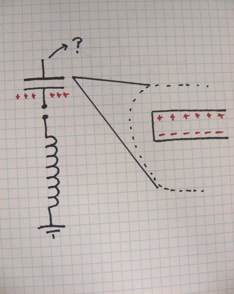
                The capacitor shown here, will not have capacitance equal to what an LCR meter would show if you hooked it between the two plates,

                Rather since you are charging an individual plate, and the other is affected through "induction by grounding" the total energy involved will be correlated to the free space capacitances of each of the plates.

                I think Harvey was trying to point this out in a round about way (not sure) but I thought I would make it more explicit. Here is a simple example, which you can try easily for yourself


                Starting at diagram ii, we see the same situation as shown in the first photo in this post.

                The red sphere represents our first capacitive plate, and it induces a separation of charges within the second plate. If this separation is strong enough, the gap between the Ariel ground and the second capacitive plate will fire. This is shown in diagram iii by the grounding "finger" reaching out and touching the second capacitive element. Once all charges have settled, the "finger" or arch dissipates, and you are left with a net charge on the second capacitive element. I would venture to guess that the energy between the two will be related to the free space capacitance of each individual element, and their respective charges.
                Last edited by Armagdn03; 07-03-2010, 03:38 PM.

                Comment


                • #38
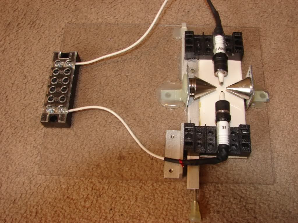
                  Here is my glue and spare parts experimental gap, which I will be using for this.

                  This uses 2 n50 neodymium magnets, oppositely polarized so that the tips pull towards each other.


                  YouTube - experimental gap.MPG

                  the next step will be to insert a glass barrier in between the gap and the magnets.


                  The AC charge will separate towards moving upwards and downwards as can be seen here. The glass will be inserted through one of these unidirectional flows. So for example, if negative ions rise, and positive fall, I will place a barrier in the path of the negative ions. As they drift upwards, the glass will bisect their path, causing a large increase in impedance. The positive ions however will have an open path around which to travel with a lower impedance.

                  Comment


                  • #39
                    Looks cool!!! Im sure your aware that some plugs have internal resistors. Looking forward to see the rest of it.

                    Comment


                    • #40
                      Originally posted by cody View Post
                      Looks cool!!! Im sure your aware that some plugs have internal resistors. Looking forward to see the rest of it.
                      I was not aware of this! thank you very much for bringing this to my attention. I will check it out, and replace if need be!

                      Comment


                      • #41
                        Nice. I like that you used spark plugs in your setup. I was just wondering whether that would be a good idea. Now I'm more encouraged to experiment with making gaps with spark plugs.

                        Comment


                        • #42
                          @Fzzzy

                          Yes, they usually are made of Tungsten-carbide, or some other very hard metal that is corrosion resistant. The trick is getting the outer shell away to expose the ceramic shaft. I did this by placing the plug into a drill, then holding it up to an angle grinder. I set them to counter rotate, so that the cutter wheel rotated one direction against the plug which rotated the opposite. This worked really well, but be careful and always where safety equipment, It is particularly dangerous holding two power tools!

                          Comment


                          • #43
                            @ Harvey

                            Originally posted by Harvey View Post
                            This is a very good point!

                            There is almost always a propagation delay through a given resistance.

                            I must admit, when I was following through the text, I was thinking in instantaneous terms and I envisaged the single pipe being added to the high pressure side of the load where it instantly boosts that section to some value above the starting point. So right away I saw that added pressure would need to go through the load or back through the pump if possible, to get to the low pressure side.

                            But once that is done (after the propagation delay) , then the entire ring is sitting at some high pressure and only the pump creates a differential in it.

                            I wonder if high pressure fluids flow differently than low pressure fluids . . .
                            Now - if the pump was an oscillating pump, flow one way and then back the other - then we could add pressure when it is going one way and take away pressure when it is going the other way and voila! we have a single tap injection that boosts an alternating current pump

                            Of course the synchronicity of them would need to be just right
                            As usual, my thread dies because I have not watered it in a while, better break the ol' watering can out.


                            Harvey, I think you see where I was going with this thread and its implications. I have been working behind the scenes, and here is an update I think you would find interesting.

                            Let me first recap what I intend to do in the working circuit, which deviates a bit from the beginning of this thread.

                            Imagine a unidirectional ring circuit, which operates as a delay line instead of a traditional circuit which operates according to well established laws. In this circuit, imagine a pulse heading in one direction, around the circuit till it reaches its initial point of disturbance. If the wavelength of the circuit is a correct multiple of the of the wavelength of the disturbance, then the next impulse will constructively add to the first after it has traveled around the ring once.

                            The interesting thing about this circuit, is that its behavior is not modeled traditionally, until you get into microwave theory, where the distinguishing lines of electrical theory and hydrodynamics are intertwined.

                            Here I would like to introduce the idea of using Bernoulli's principle as applied to aether hydrodynamics and electrical "circuit" theory. While I was pondering this concept I came across an interesting paper by Frederick David Tombe,Formerly a Physics Teacher at College of Technology Belfast, and Royal Belfast Academical Institution, entitled "Bernoulli’s Principle and the AC Transformer"

                            http://www.wbabin.net/science/tombe35.pdf

                            I was blown away when what I was reading was the very problem, and thought process I had just written in my notes.

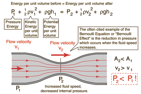
                            In Bernoulli's principle we equate the Energy per unit volume at one point, to the energy per unit volume at a second point with a higher impedance.


                            Notice the relationships to the right of the pipe.

                            We can apply this to electrodynamics (using the hydrodynamic model) and re write the equation for electrical purposes, when we view the space in and around our circuit as a compressible fluid. (I don't think many here will argue that it is not).

                            The re-written equation would look like

                            V1*I1 = V2*I2 for voltage times amperage at point (1) equals voltage and amperage at point (2). Because we are dealing resonant structures (coils) with inherant capacitive and inductive qualities, we can immediately apply the energy stored in these elements at a given point (P1 and P2).

                            Writing the equation integrating it with time we get....

                            1/2CV˛ + 1/2LI˛ = 1/2CV˛ + 1/2LI˛

                            So what does this all mean?

                            Imagine a resonant wave guide, with a resistor in the path of it. As the unidirectional wave transverses the guide, and reaches the resistive element (restricted section in the image for Bernoulli's principle) we will see an increase in in velocity of the wave, a decrease in pressure of the wave, which correlates directly to Voltage and Amperage. We essentially transform the propagating waves energy from one form to another, as it passes through the resistive element. Then as it passes past the restriction (resistor) it will transform again (refer back constantly to water pipe analogy with compressible fluid).

                            When viewed from this frame-set the resistor dissipates NO ENERGY, rather energy is simply transformed as it passes through it, and transforms again as it leaves it.

                            Many people have probably noticed a version of this phenomenon by dissipating energy stored in an inductor through a resistor. The inductor raises the potential to overcome any and all impedance, and lowers its amperage accordingly, this is Bernoulli's principle applied to electro-hydrodynamics.

                            Note:

                            It is also possible to have a reflection from our impedance. This is why it is very important to have the sections of our ring be wavelength multiples, so that anything that is reflected back eventually bounces back to add constructively to the next passing wave, and no reflection from the impedance is EVER lost!

                            I would like to add a few select paragraphs from the paper I cited with a few notes of my own inserted in red to help the reader along and make connections.

                            The Electropolarization Wave
                            III. There is no official recognition in modern physics of the existence of
                            an electropolarization wave (the stretch wave (longitudinal)). However electrical power
                            is clearly not being carried by electromagnetic radiation (The spin wave(Transverse))
                            because this only oscillates inwards and outwards perpendicularly to the
                            wires. Neither can substantial electrical power in high tension crosscountry
                            cables be carried conventional electric current in the wire because
                            this has been made deliberately small to minimize resistive losses.
                            The missing factor in AC power transmission can be adequately
                            accounted for by the propagation of linear polarization of electric dipoles
                            both inside the wires and in the electron-positron sea in the space beyond
                            the wires, with the main action occurring inside the wires.
                            Conclusion
                            IV. Electric current can clearly take on the form of a free flow of charged
                            particles (slide) or an elastic displacement of dipoles (stretch). The AC
                            transformer is a device which can convert between slide and stretch. Slide
                            is associated with kinetic energy whereas stretch is associated with
                            potential energy, voltage, or pressure. Electrical pressure is erroneously
                            referred to as tension but in fact the tension in the stretched dipoles is a
                            reaction to the vitreous aether pressure which is ultimately caused by
                            fine-grain centrifugal force.
                            The common link between these two kinds of electric current is the flow
                            of vitreous aether which constitutes an electric field. The kinetic energy
                            1/2LI˛ associated with this flow will result in resistive losses and the
                            conversion of some of this kinetic energy into heat. These resistive losses
                            are known as the I˛Rt factor and they can be minimized by the
                            transformer.
                            When the electric field results in the linear polarization of dipoles, then
                            we will obtain capacitative potential energy (pressure) given by the
                            expression 1/2CV˛.
                            The flow of pressurized vitreous aether can be compared to the flow of a
                            pressurized gas in a pipe, however, in an electric circuit the pressurized
                            vitreous aether can leak into the surroundings depending on the dielectric
                            constant of the surrounding medium.
                            Cool....No?
                            Last edited by Armagdn03; 07-22-2010, 05:54 PM.

                            Comment


                            • #44
                              Is this the same effect as with a liquid in the circular hose? IF YOU SQUEEZE the hose at a certain point the liquid starts to flow in one dirrection.

                              Comment


                              • #45
                                Originally posted by bboj View Post
                                Is this the same effect as with a liquid in the circular hose? IF YOU SQUEEZE the hose at a certain point the liquid starts to flow in one dirrection.
                                Good question,

                                the answer is no, if you squeeze a circular hoze you will cause a wave to propagate in two directions OR increase the pressure throughout the entire hose. If you wanted to make an equivalent, it would be a circular hose with a check valve in it. Then squeeze the hose so fast, that it creates a shock wave that travels down the hose, but because it has a check valve it can only go in one direction. When the shock wave travels all the way down the hose, back to the point where it started, another is introduced, and constructively adds to the first.

                                There is a story, cannot for the life of me find it, about a man who was watching a wave travel down an irrigation channel. He followed the wave on his horse, noticing that for miles and miles the wave traveled same speed, never loosing any amplitude. This is an extension of the derivation of an electric field off of an infinite plane. The field strength is uniform into infinity, no matter how far you get from the plane, because the energy has no way of diverging from any one point, same as a wave in a Chanel, it cannot "spread out" so it retains its energy and just keeps going. Imagine a circular irrigation channel, now stick a narrow section in it, how would we model the wave traveling through this section??? BERNOULLIS PRINCIPLE!!! pressure through the channel will drop, velocity will increase, but energy per unit volume will remain the same! Because the principle is a conservation of energy equation, we know that no energy can possibly be lost to the resistive element in the circuit I describe, it simply changes form, then changes back, keeping energy constant.

                                Comment

                                Working...
                                X