Announcement

Collapse
No announcement yet.

Capacitive Sink Hole

Collapse
X
 
  • Filter
  • Time
  • Show
Clear All
new posts

  • #46
    ring circuit...

    Below is a circuit that I used a PWM driver, a ferrite toroid, and a ring of copper tubing separated with a cap. Essentially a tank circuit. Connected to the ring was a parallel wired LED bank. The circuit, while lighting the LED's, uses very little energy and displays some interesting scope shots...

    Since I'm still in the learning process it takes me alot more time to digest the outcome of my experiments. Below is a screen shot of the scope and ring circuit....

    I'm not sure this is directly related to what your doing but has similarities to your description.

    I tried a couple tank circuits using the "C-stack" idea but so far haven't had much success in removing energy from it without disturbing the tank resonance... which has been the case in quite a few of my attemps in various forms.

    I've also been studying the Cook coils with the idea the coil layout is based on a concentric capacitor to create the oscillations. I haven't achieved any self oscillation of the coil system but oddly enough when you drive the iron core with a single lead from the FG the coils seem to come to life. My coils aren't built to specs by any means - far less than the 1000 ft stated in the patent. No real success with this experiment either. Interesting though....
    ________
    Wendie 99
    Last edited by dragon; 10-24-2014, 12:03 AM.

    Comment


    • #47
      Originally posted by dragon View Post
      Below is a circuit that I used a PWM driver, a ferrite toroid, and a ring of copper tubing separated with a cap. Essentially a tank circuit. Connected to the ring was a parallel wired LED bank. The circuit, while lighting the LED's, uses very little energy and displays some interesting scope shots...

      Since I'm still in the learning process it takes me alot more time to digest the outcome of my experiments. Below is a screen shot of the scope and ring circuit....

      I'm not sure this is directly related to what your doing but has similarities to your description.

      I tried a couple tank circuits using the "C-stack" idea but so far haven't had much success in removing energy from it without disturbing the tank resonance... which has been the case in quite a few of my attemps in various forms.

      I've also been studying the Cook coils with the idea the coil layout is based on a concentric capacitor to create the oscillations. I haven't achieved any self oscillation of the coil system but oddly enough when you drive the iron core with a single lead from the FG the coils seem to come to life. My coils aren't built to specs by any means - far less than the 1000 ft stated in the patent. No real success with this experiment either. Interesting though....
      Hello dragon!

      That is a very nice little project. It is not though what I am trying to describe. In a typical tank circuit, you cannot have unidirectional flow, because the capacitor acts as a charge blocking mechanism, and does not allow a current to head in one direction only, rather it heads one direction then reverses and heads in reverse. Think more of a circular tube, bent into a ring, where you make a compression (sound) wave through it which travels in one direction around the ring, not both.

      Comment


      • #48
        Originally posted by Armagdn03 View Post
        Hello dragon!

        That is a very nice little project. It is not though what I am trying to describe. In a typical tank circuit, you cannot have unidirectional flow, because the capacitor acts as a charge blocking mechanism, and does not allow a current to head in one direction only, rather it heads one direction then reverses and heads in reverse. Think more of a circular tube, bent into a ring, where you make a compression (sound) wave through it which travels in one direction around the ring, not both.
        Thanks, it was fun and challenging although the end result was different than I was looking for.

        So in an electrical version of the ring and sound wave you would have something similar to a tesla coil with the primary in the center and instead of a long straight coil it would be wound on a plastic toroid with a resistance connecting the ends. Hitting the primary with only a positive pulse? Is that closer to your description... trying to make a mental picture...

        I can see the water anology ( being more mechanicaly inclined ) and can envision the sound wave but my brain doesn't process electrons as well...
        ________
        ALASKA DISPENSARIES
        Last edited by dragon; 05-11-2011, 10:37 AM.

        Comment


        • #49
          Originally posted by Armagdn03 View Post
          Good question,

          the answer is no, if you squeeze a circular hoze you will cause a wave to propagate in two directions OR increase the pressure throughout the entire hose. If you wanted to make an equivalent, it would be a circular hose with a check valve in it. Then squeeze the hose so fast, that it creates a shock wave that travels down the hose, but because it has a check valve it can only go in one direction. When the shock wave travels all the way down the hose, back to the point where it started, another is introduced, and constructively adds to the first.

          There is a story, cannot for the life of me find it, about a man who was watching a wave travel down an irrigation channel. He followed the wave on his horse, noticing that for miles and miles the wave traveled same speed, never loosing any amplitude. This is an extension of the derivation of an electric field off of an infinite plane. The field strength is uniform into infinity, no matter how far you get from the plane, because the energy has no way of diverging from any one point, same as a wave in a Chanel, it cannot "spread out" so it retains its energy and just keeps going. Imagine a circular irrigation channel, now stick a narrow section in it, how would we model the wave traveling through this section??? BERNOULLIS PRINCIPLE!!! pressure through the channel will drop, velocity will increase, but energy per unit volume will remain the same! Because the principle is a conservation of energy equation, we know that no energy can possibly be lost to the resistive element in the circuit I describe, it simply changes form, then changes back, keeping energy constant.
          I undarstand your point. I am not a physicist but Iam sure there is a certin phenomenon - don't know the name - whe re you get a unidirectional flow in the hose - not only the shock wawes.
          It may not be related to your post though.

          Comment


          • #50
            @Armagdn03,

            I just got back from a trip and am a bit fatigued - trying to catch up on some posts here at EF

            That is definitely a different approach to looking at things and I need to spend some time on it when I am not so tired. But here is a quick overview.

            Naturally, my conventional training kicks in right away which says a resistor does not recover the V on the output so Vin - Vmiddle - Vout typically show a loss by the time we reach Vout and Vmiddle is typically a gradient between them.

            So, I have to set that aside and look at things how the author is explaining it where the 'restriction' is not resistive, but is an impedance, such as in an AC transformer with very low resistance windings. Now, two such transformers back to back would represent the Bernoulli arrangement as depicted. Let us say we have:
            ------------------\_______________/----------------
            [GEN ->120VAC > 12VAC = 12VAC > 120VAC -> Load]
            ------------------/```````````````\----------------

            And for ease of discussion, we will do 1A from the GEN so the power is 120W. In the wires depicted by the = sign we have the Bernoulli restriction. The voltage (Pressure) is dropped by a factor of 10 and the Current (Flow) is increased by a factor of 10 in those wires. Of course our load will dissipate the 120W or else the power is only apparent and gets returned to the Generator without doing work.

            But I think the author there is doing something further with capacitance - I'll need to check it better tomorrow . . . um later today o.O

            "Amy Pond, there is something you need to understand, and someday your life may depend on it: I am definitely a madman with a box." ~The Doctor

            Comment


            • #51
              Originally posted by Harvey View Post
              @Armagdn03,

              I just got back from a trip and am a bit fatigued - trying to catch up on some posts here at EF

              That is definitely a different approach to looking at things and I need to spend some time on it when I am not so tired. But here is a quick overview.

              Naturally, my conventional training kicks in right away which says a resistor does not recover the V on the output so Vin - Vmiddle - Vout typically show a loss by the time we reach Vout and Vmiddle is typically a gradient between them.

              So, I have to set that aside and look at things how the author is explaining it where the 'restriction' is not resistive, but is an impedance, such as in an AC transformer with very low resistance windings. Now, two such transformers back to back would represent the Bernoulli arrangement as depicted. Let us say we have:
              ------------------\_______________/----------------
              [GEN ->120VAC > 12VAC = 12VAC > 120VAC -> Load]
              ------------------/```````````````\----------------

              And for ease of discussion, we will do 1A from the GEN so the power is 120W. In the wires depicted by the = sign we have the Bernoulli restriction. The voltage (Pressure) is dropped by a factor of 10 and the Current (Flow) is increased by a factor of 10 in those wires. Of course our load will dissipate the 120W or else the power is only apparent and gets returned to the Generator without doing work.

              But I think the author there is doing something further with capacitance - I'll need to check it better tomorrow . . . um later today o.O


              Perhaps the question to ask then is this...if you send a compression wave down the electrical waveguide, through an impedance.....will the energy of the wave AFTER the impedance be equivalent to the energy of the wave before it? (ignoring the fact that it could be partially reflected, because the device can be built so as to never loos this energy) So does the impedance (ohmic) in fact dissipate energy??? Or does it act as a transformer and change it, then change it back?

              Comment


              • #52
                Originally posted by Armagdn03 View Post
                Perhaps the question to ask then is this...if you send a compression wave down the electrical waveguide, through an impedance.....will the energy of the wave AFTER the impedance be equivalent to the energy of the wave before it? (ignoring the fact that it could be partially reflected, because the device can be built so as to never loos this energy) So does the impedance (ohmic) in fact dissipate energy??? Or does it act as a transformer and change it, then change it back?
                The answer (with another question ) to this question is....

                If you believe you can apply Bernoulli's principle to this situation, then there will be a conservation of energy through the path of the wave, it can change forms many times, but the same energy per unit volume stays. In fact Bernoulli's equation can be derived from the conservation of energy laws.

                Many times the derivation of bernoulli's equation for compressible fluids states the limitation that it holds for fluid flows moving at low "mach" numbers, and assumes a continual flow. (this is similar to conventional circuit theory)

                This is interesting because when we get into high mach numbers, we are approaching the longitudinal wave zone, where compression waves can occur, giving rise to differing potentials and kinetic energies along any two points along the wave guide, rather than equal all along the wave guide.

                I need to do some basic testing here, I dont want to delve to far into the concept without some real world connections (experimentation).

                Comment


                • #53
                  Originally posted by Armagdn03 View Post
                  ....
                  There is a story, cannot for the life of me find it, about a man who was watching a wave travel down an irrigation channel. He followed the wave on his horse, noticing that for miles and miles the wave traveled same speed, never loosing any amplitude.
                  Hi,

                  Here is a link on the story you wanted to recall, the wave was later called soliton wave, the person first watching it was John Scott Russel.

                  John Scott Russell and the solitary wave

                  greetings, Gyula

                  Comment


                  • #54
                    Originally posted by gyula View Post
                    Hi,

                    Here is a link on the story you wanted to recall, the wave was later called soliton wave, the person first watching it was John Scott Russel.

                    John Scott Russell and the solitary wave

                    greetings, Gyula

                    Wow! thank you sooo much, I searched for that article for a couple hours and could not find it!

                    Comment


                    • #55
                      Originally posted by Armagdn03 View Post
                      The answer (with another question ) to this question is....

                      If you believe you can apply Bernoulli's principle to this situation, then there will be a conservation of energy through the path of the wave, it can change forms many times, but the same energy per unit volume stays. In fact Bernoulli's equation can be derived from the conservation of energy laws.

                      Many times the derivation of bernoulli's equation for compressible fluids states the limitation that it holds for fluid flows moving at low "mach" numbers, and assumes a continual flow. (this is similar to conventional circuit theory)

                      This is interesting because when we get into high mach numbers, we are approaching the longitudinal wave zone, where compression waves can occur, giving rise to differing potentials and kinetic energies along any two points along the wave guide, rather than equal all along the wave guide.

                      I need to do some basic testing here, I dont want to delve to far into the concept without some real world connections (experimentation).
                      Ok, I did read that fellow's PDF and even perused a couple others in his links - unfortunately, in my honest opinion, he has some mistakes in his works that left me not wanting to read any more of his stuff but that is probably more related to my having too much to read already than not wanting to read his material. If I felt there was something in them that would be beneficial, then I would probably take the time to read them all. No disrespect intended, just my personal preferences.

                      One thing, that is rather glaring to me, is the inverse analogy problem in his title. You will note that in my previous post, which I was admittedly quite tired when I wrote it, I was still able to correlate the relationship between Pressure and Voltage along with Fluid Flow and Current. But in Tombe's work, he somehow inverts this principle leaving the analogy broken. I think he was trying to relate reduced current in power transmission lines with reduced pressure in a Venturi following the Bernoulli Principle. This is an incorrect analogy as he is swapping the roles of Voltage and Current. It is possible that he has held the roles in place, but swapped the Venturi function so that it is a widening in the middle instead. If this was his intent, it certainly was not well stated, but in that case I can agree with the analogy. So, the Generator and the Load are at the restricted ends of a wide path. The high tension wires represent a wide analogous path because the current is low for the same power. In this case, simply reverse the roles of the transformers in my diagram to illustrate that effect.

                      He mentions capacitance and I have to state outright that all conductors, even a straight wire, is a capacitor. In fact, anything that can store an electrical charge can be called a capacitor because it has some capacity to store charge. What he does not go into deeply enough, is that the vacuum of space between atoms is a dielectric. And therefore, each free electron in a conductor acts as an independent capacitor relative to its neighbors. As the distance between electrons decreases, the voltage in the conductor increases - this is the tension. A conductor under high tension will pass a wave much more thoroughly than one that is not under tension and this helps to reduce resistive losses (which is the result of wide distributive motion of electrons in the conductor). Instead of the electrons bouncing around in the wire, they are tightly distributed and held in an elastic framework so that energy propagates not by kinetic collision but by electrical repulsion propagation. So a tension wave inserted at one end of a 500,000V wire will propagate cleanly to the other end with minimal resistive losses with a modicum of current. And at the fundamental level, this is really a capacitive transfer.

                      Where we run into a problem with modern electrodynamics, is applying the power to do work. This is the place that most electrical systems fail to measure up because their efficiency is so poor. Even our gasoline powered vehicles are only 30% efficient, wasting most of the energy as heat to be dissipated into the air. Newer electric motors are upwards above 80% efficient, and that is a good thing - but we do wonder if it is the right way to do things.

                      The whole matter of electrical use gets broken down into some basic areas with examples:

                      1. Kinetic Energy - motor motion
                      2. Thermal Energy - heating or cooling
                      3. Electromagnetic Energy - Light, Radio
                      4. Electricity Direct Use - Electro-stimulation, Battery Charging, Amusement & Research

                      The nice thing about electricity is that it is easily converted between different forms of energy. When we as a species apply our skills and knowledge to make these conversions more efficient, then I think we will be taking a leap forward globally.

                      Now, if the Earth itself is pulsing electrically, and we know it is because it is continually resonating due to the 16 million lighting storms that occur each year, then perhaps we can let that pulse drive our systems. So the quest will be how to harness the energy represented by those pulses. and do so in the most efficient manner. And of course the question will be; If we take that energy for our use, what effect will it have on the global weather system?

                      Tesla, Moray, Marks and Schwartz all seem to have tapped into it by different means, but something seems to be holding humanity back from applying it. Humanity embraced AC with open arms and the uses it as a life blood and it was only a small seedling that spawned that. Why do the seeds of this other technology not germinate? Or if they do, why does it die? Perhaps unseen powers know better than we the outworking of stealing this energy for ourselves and have been holding us back from using it. At least it sure seems that way

                      So, the simple answer: Charge your wires to a voltage just short of dielectric breakdown of air and run your waves across those wires.

                      Last edited by Harvey; 07-23-2010, 10:46 PM.
                      "Amy Pond, there is something you need to understand, and someday your life may depend on it: I am definitely a madman with a box." ~The Doctor

                      Comment


                      • #56
                        Originally posted by Harvey View Post
                        Ok, I did read that fellow's PDF and even perused a couple others in his links - unfortunately, in my honest opinion, he has some mistakes in his works that left me not wanting to read any more of his stuff but that is probably more related to my having too much to read already than not wanting to read his material. If I felt there was something in them that would be beneficial, then I would probably take the time to read them all. No disrespect intended, just my personal preferences.

                        One thing, that is rather glaring to me, is the inverse analogy problem in his title. You will note that in my previous post, which I was admittedly quite tired when I wrote it, I was still able to correlate the relationship between Pressure and Voltage along with Fluid Flow and Current. But in Tombe's work, he somehow inverts this principle leaving the analogy broken. I think he was trying to relate reduced current in power transmission lines with reduced pressure in a Venturi following the Bernoulli Principle. This is an incorrect analogy as he is swapping the roles of Voltage and Current. It is possible that he has held the roles in place, but swapped the Venturi function so that it is a widening in the middle instead. If this was his intent, it certainly was not well stated, but in that case I can agree with the analogy. So, the Generator and the Load are at the restricted ends of a wide path. The high tension wires represent a wide analogous path because the current is low for the same power. In this case, simply reverse the roles of the transformers in my diagram to illustrate that effect.

                        He mentions capacitance and I have to state outright that all conductors, even a straight wire, is a capacitor. In fact, anything that can store an electrical charge can be called a capacitor because it has some capacity to store charge. What he does not go into deeply enough, is that the vacuum of space between atoms is a dielectric. And therefore, each free electron in a conductor acts as an independent capacitor relative to its neighbors. As the distance between electrons decreases, the voltage in the conductor increases - this is the tension. A conductor under high tension will pass a wave much more thoroughly than one that is not under tension and this helps to reduce resistive losses (which is the result of wide distributive motion of electrons in the conductor). Instead of the electrons bouncing around in the wire, they are tightly distributed and held in an elastic framework so that energy propagates not by kinetic collision but by electrical repulsion propagation. So a tension wave inserted at one end of a 500,000V wire will propagate cleanly to the other end with minimal resistive losses with a modicum of current. And at the fundamental level, this is really a capacitive transfer.

                        Where we run into a problem with modern electrodynamics, is applying the power to do work. This is the place that most electrical systems fail to measure up because their efficiency is so poor. Even our gasoline powered vehicles are only 30% efficient, wasting most of the energy as heat to be dissipated into the air. Newer electric motors are upwards above 80% efficient, and that is a good thing - but we do wonder if it is the right way to do things.

                        The whole matter of electrical use gets broken down into some basic areas with examples:

                        1. Kinetic Energy - motor motion
                        2. Thermal Energy - heating or cooling
                        3. Electromagnetic Energy - Light, Radio
                        4. Electricity Direct Use - Electro-stimulation, Battery Charging, Amusement & Research

                        The nice thing about electricity is that it is easily converted between different forms of energy. When we as a species apply our skills and knowledge to make these conversions more efficient, then I think we will be taking a leap forward globally.

                        Now, if the Earth itself is pulsing electrically, and we know it is because it is continually resonating due to the 16 million lighting storms that occur each year, then perhaps we can let that pulse drive our systems. So the quest will be how to harness the energy represented by those pulses. and do so in the most efficient manner. And of course the question will be; If we take that energy for our use, what effect will it have on the global weather system?

                        Tesla, Moray, Marks and Schwartz all seem to have tapped into it by different means, but something seems to be holding humanity back from applying it. Humanity embraced AC with open arms and the uses it as a life blood and it was only a small seedling that spawned that. Why do the seeds of this other technology not germinate? Or if they do, why does it die? Perhaps unseen powers know better than we the outworking of stealing this energy for ourselves and have been holding us back from using it. At least it sure seems that way
                        So, the simple answer: Charge your wires to a voltage just short of dielectric breakdown of air and run your waves across those wires.


                        Thanks for the reply Harvey,

                        I have read over several of his papers and I see what you mean by short falls. I actually posted that link to that paper as I was writing the post, and didn't really go over it, which isn't really the greatest idea!

                        Let me try to re phrase my argument, without the use of that paper clouding the intent.

                        In a standard water pipe, you have what might be considered a continual flow of a non compressible medium (water) Bernoulli's principle equates the impedance, pressure and velocity. This is very much how we view modern circuit theory and ohms law.

                        However the reality of the situation is, that water is not incompressible. If water was incompressible, we could not send sound waves through it, and we would have a material which could transmit information faster than the speed of light. You could interpret the limit of Zero compressibility as

                        "if you could get sound to propagate through an incompressible object it would travel at "infinite" speed but it is "infinitely" difficult to get the sound wave to propagate through the medium in the first place. In other words, a large block of incompressible stuff just reflects sound waves perfectly back" -Douglas Standford-
                        This is interesting as we view the propagation of a wave through space with a definite change in quality through it.

                        In our case we have a restricted path (pipe) which causes compression waves to be non dispersive, because there is no divergence from any single point. We can introduce a restriction.

                        If we view this pipe from the conventional model in simplicity, we will say that the impedance from the restriction is immediately felt by any fluid flow. This is very similar to ohms law, where the impedance dictates the ratio of voltage to amperage.

                        If we recognize however that water is NOT incompressible, we can introduce the idea of non dissipative longitudinal waves (water hammer). This is different because to the initial impulse, the impedance might as well not be there, for it is at the moment invisible. The speed and other characteristics of the wave are a result of the initial device impinging the disturbance, and the immediate medium to which it is imparted. As the wave pack travels down the pipe, it after a time encounters the impedance. Here two things can happen (and this reminds me very much of Snell's Law and index of refraction) some of the energy will travel through the impedance, and some will be reflected.

                        I believe that the energy which passes through the impedance will have a characteristic change via a Bernoulli like principle. Change the impedance, and the ratio of current to potential will change as well.

                        But as we know some of this energy will also be reflected as noted before. If this reflected energy heads backwards, opposite to the initial direction of propagation (hence a reflection ) and returns to the start of our pipe to be constructively added to the next impulse, we will have wave addition and superposition causing the next impulse to be greater. This cycle may continue until an equilibrium is reached.

                        In this model, nothing is ever Dissipated due to an ohmic resistance. Part of the energy passes through the impedance transformed, and part is reflected. If done properly the reflected energy can be added to the next impulse to be recycled.

                        If our circuit is built into a unidirectional ring circuit, then you could build to achieve the following:

                        1) You have a ring circuit, which has an initial point of excitation.
                        The ratio of amperage and voltage and speed of propagation imparted to the circuit at this point is local only to this point, and it will create a unidirectional soliton, or wave packet traveling solely in one direction around the circuit. This Soliton will be non dispersive due to the nature our waveguide.

                        2) The soliton will meet an impedance. Part of its energy will pass through the impedance and will have a NEW characteristic amperage, potential and electrical velocity, which is dictated by the characteristics of the impedance.
                        After passing through the impedance this wave will alter again, as it exits the impedance and returns to the waveguide. Here the wave will circularly travel to back to the initial point of excitation.

                        3)Part of the energy impulse hitting the impedance will be reflected back to its original point of excitation to be constructively added to the next impulse.

                        4) The energy reflected + energy transformed through the impedance = Total energy imparted to the system through initial impulse. This does not view the impedance as able to dissipate energy in the classical sense, simply transform it.

                        5) If built correctly, the reflected wave and the the impulse which went through the impedance will both meet back at the point of initial excitation at the EXACT SAME TIME. There the second impulse, the reflected wave, and the wave which went full circle (through the impedance) will all add constructively to create an impulse with perhaps twice the amplitude of the first.

                        (Impulse sent through impedance + impulse reflected) + second impulse = Larger soliton to be sent around the circle again.

                        Each cycle the soliton will grow and grow. The ratios will stay the same, but amplitude will increase and increase.

                        The trick is to inserting the impedance, and the unidirectional "spark gap" into the correct position around the ring to allow for correct superposition of all components.

                        It is very easy to see from this little mind experiment, why impedances look like a dissipative loss in the traditional incompressible fluid model, as the impedance is immediately felt by any fluid flow. However when we concede that there is a measure of compressibility (capacity), we may note that the impedance may only be felt as it is encountered by a soliton, and the energy will behave in a more interesting way!

                        Comment


                        • #57
                          Can you make it a bit clearer. If I get it right you send a pulse. Than you have a traveling pulse and a flow of water. After the part of a pulse is reflected in what direction it travels? wilo it not cancel the succeding pulse?

                          Comment


                          • #58
                            Originally posted by bboj View Post
                            Can you make it a bit clearer. If I get it right you send a pulse. Than you have a traveling pulse and a flow of water. After the part of a pulse is reflected in what direction it travels? wilo it not cancel the succeding pulse?


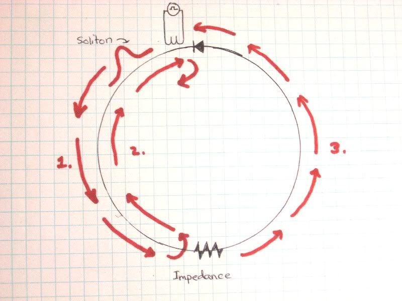
                            Here an initial impulse is given by the unidirectional discharge of a capacitor through a turn or two of wire. (shown as little black primary on upper part of photo in black)

                            The soliton will travel down the wave guide in only one direction, because the other direction is blocked by a diode, or other device which has a larger impedance in one direction than the other. This is shown as number (1.) by red arrows.

                            When the soliton reaches the impedance at the bottom of the circle, it partially bounces back (number (2) in red) and partially continues through (number (3) in red). When number 2 in red hits the diode or super large impedance it will reflect again, heading in the same direction as arrow 1 in red, now they may constructively add.

                            Arrow number 3 is also in the correct direction for addition. and if timed correctly (not terribly difficult) ten you will have the superposition of wave 1 as it bounces off the impedance, then off of the diode (shown as wave 2), and wave wave 3 which passes full circle.

                            Also watch this video of two solitons in opposite directions colliding. This will never happen in this device, but interesting none the less.

                            YouTube - Collision de solitons hydrodynamiques

                            Does this make sense to people?
                            Last edited by Armagdn03; 07-27-2010, 08:35 PM.

                            Comment


                            • #59
                              It is clear now. But what do you gain with adding of the pulses? Also I am not sure that would be so easy to achieve. In a sense you are creating an unbalanced circut. Faster growing energy pulse on the left compared to the right half.
                              Also what is a function of impedance. What is the equation to calculate how much is reflected and how much passes through.
                              At first it looks as it will grow by itself if there are no losses.

                              Comment


                              • #60
                                Originally posted by bboj View Post
                                It is clear now. But what do you gain with adding of the pulses? Also I am not sure that would be so easy to achieve. In a sense you are creating an unbalanced circut. Faster growing energy pulse on the left compared to the right half.
                                Also what is a function of impedance. What is the equation to calculate how much is reflected and how much passes through.
                                At first it looks as it will grow by itself if there are no losses.

                                Well...What do you gain out of having impulses of immense size traveling through a bank of resistive light bulbs? Do resistive loads really dissipate energy by conversion? or are we looking at things a bit askew. What exactly is the mechanism transforming amperage to heat and light?

                                If resistances dissipate (I hold that they do not) then as the pulse enters the resistive load, it will not come back out. It will be converted into light and heat, and the pulse cannot possibly exit the resistance, since it was all converted..This to me does not seem plausible.

                                Also, this entire circuit is at any one point unbalanced! this is a delay line, not a circuit in the traditional sense. There will never be equal amperage between any two points. And as to the ease, If you know about electrical length, wavelength, resonant frequency, and delay lines it should not be hard, especially since the circuit should be symmetrical.
                                Last edited by Armagdn03; 07-27-2010, 09:48 PM.

                                Comment

                                Working...
                                X