Announcement

Collapse
No announcement yet.

The inverse of the "Inverse Transformer"

Collapse
X
 
  • Filter
  • Time
  • Show
Clear All
new posts

  • The inverse of the "Inverse Transformer"

    A long time ago, in an apartment far far away, I built a small test rig I titled the Inverse Transformer. I have thought about it ever since.

    YouTube - Inverse Transformer.wmv

    Before I can get to my point, I have to explain the device a bit.

    1)The input into the device is a rotating disk with magnets of alternating polarity.

    2)The "primary" of the transformer is a ferrite core with 1 turn.

    3)The "core" is an electrical winding of copper, with 300 or so turns.

    4) The "secondary" is a ferrite core with 1 turn.

    When the secondary is left open, we see Lenz generator drag on the rotor. The magnetic primary induces a current within the copper core, which opposes the motion which created it.

    When the secondary is closed, it creates an equal and opposite force within the electrical winding which opposes the first current. The rotor now rotates much more freely, with very little drag.

    THINK ABOUT THIS....

    The addition of a closed path on the secondary is the equivalent of shorting the secondary on a normal transformer. This act lets the rotor rotate freely, almost eliminating the impedance to the rotor. A dead short, or the largest possible LOAD on the secondary, constitutes a free spinning rotor with minimal drag. We are loading it to the max on the output, and the result is free passage of the rotor, or minimal consumption on the input.


    This is very similar to a normal transformer, in that shorting the secondary, reduces the impedance in the primary, allowing more current to pass through the primary. This increase in current in the primary, NORMALLY constitutes increased energy consumption at the source, but that is only because we have chosen an INCORRECT SOURCE.

    Imagine instead an inverse inverse transformer.

    In place of magnets we could place electrically charged plates, in alternating predominance. Think the exact same setup as in the video above, except that in place of magnets we have electrostatic elements. In place of magnetic primary and secondary, we have electric conductors. In place of an electric core, we have a magnetic core.

    Now what happens when we load this machine? questions to consider...

    1) if we leave the secondary open, will we see a Lenz drag on the rotor? (the same as if we left the secondary open on the video above, where we saw a drag with the open magnetic secondary)

    2)If we dead short the secondary of our inverse inverse transformer, will it induce an equal and opposite magnetic component within the magnetic core? Modern transformer theory says YES definitely we will. Will the result of this be a decrease in impedance of the primary winding? Modern transformer theory says YES definitely we will.

    If there is very little impedance in the primary, does equate to a free spinning rotor? Are we allowing the free passage of electrical energy through the primary, which results in little or no drag on our electrostatic rotor?


    In the inverse transformer, our secondary is magnetic, it is hard to use this in our electrically oriented circuits, and the demo shows a dead short equates to a free spinning rotor, which is the equivalent of maximum current draw at the secondary.

    If we do the inverse of this, replace magnets with electrets, can we cause a situation where a shorting of the secondary creates a free passage of the electret rotor?


    In a normal generator, the relationship is, increased current draw equates to increased mechanical load.

    In an "inverse generator", or "inverse inverse generator" (or I like to call it the inverse^2 generator ) the relationship is increased draw at the secondary equates to decreased mechanical load on our rotor. Here the closer you get to a dead short, the better! But if there is no load on the secondary, we might just see a heavy drag on the rotor...what an interesting inverse relationship!!!
  • #2
    Is this core basically an " H " core ? I watched the video sometime back but didn't understand how the core was formed. Is this similar to the units you PM'd me about a bit ago? Did you get some drawings together for that particular system ?
    ________
    IOLITE PORTABLE VAPORIZER
    Last edited by dragon; 05-11-2011, 10:35 AM.

    Comment


    • #3
      Here is a very interesting application to the above. (one might want to fully understand the above post before trying to understand this one)


      Lets do away with the rotor, and in place lets use some solid state equipment.

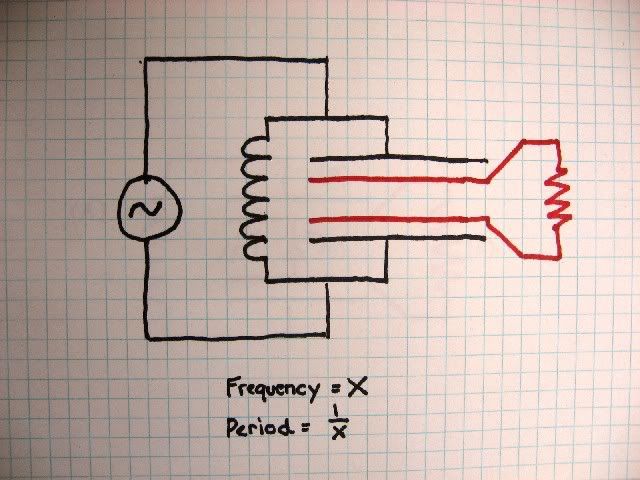
      In place of a rotating mechanical disk, we ill use a parallel configured LC tank circuit. The capacitor will be a specially created capacitor with 4 plates. This will be very similar to construction of a C stack by Cris Paltenghe

      The C-Stack by Cris Paltenghe


      Consider the outer 2 plates of the specialized capacitor to be connected to the inductor to create our Tank circuit.

      Consider the inner 2 plates of the specialized capacitor to be connected to a resistive load.


      The Q of our oscillator is dependent on the action of the flow of current through the RC circuit with the load.

      If we have a high resistance load for example, the discharge of the inner plates through the load, will be slower than the period of the oscillator and so will constitute "drag" on the tank circuit reducing its Q.

      However if the RC time constant of the inner plates and the load, (five time constants in all) is less than 1/4 the frequency of the oscillator, it will appear as invisible to the tank circuit! Let me explain better.


      The full frequency of the oscillator constitutes a charge of the capacitor (1/4 of frequency) the discharge of the capacitor into inductor (1/4 of frequency) the reverse charge of the capacitor (1/4 of frequency) and the discharge of the reverse charge (1/4 of frequency). This cycle makes constitutes 1 full wave.

      If our load is highly resistive, the inner plates will discharge through the load at a slower rate than the outer plates into the inductor. Because the outer and inner plates are connected to the hip so to speak, this will cause a "drag" on the LC oscillator, which constitutes energy loss. However, if the 5 RC time constants (this equates to 99% discharge of the inner plates through load) is quicker than 1 charge or discharge cycle of the capacitor (1/4 of frequency) then it is possible that the inner plates and load appear "invisible" to the oscillator and constitute no real load.


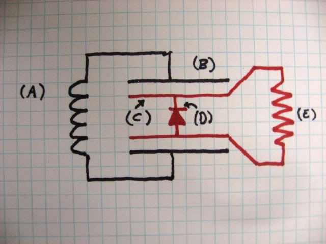
      An easy to imagine variation on this involves sticking in a diode.


      Here we can imagine the process.

      1) The inductor (A) Discharges into outer capacitor plates (B). The diode (D) represents a path of least resistance to the charging of the inner capacitor (C).

      2) Outer capacitor plates (B) now want to discharge back into inductor (A). This releases the charge the outer plates held in place on inner capacitor (C). Inner capacitor (C) now finds its path of least resistance to be the load (E). If inner capacitor (C) cannot discharge fully through (E) by the time 1/4 of the frequency time has passed, then it will have residual charge left on it. This residual charge means that the outer capacitor (B) will also not be able to fully discharge. If it cannot fully discharge, it is not returning all of its energy to the inductor, and essentially we have loss in the LC circuit created by (B) and (A).

      3) If however the RC time constant times 5 (99% discharge) of the inner plates (C) and load (E) is quicker than the time elapsed in 1/4 the natural frequency of the tank circuit, then no charge will be left on the inner capacitor (C), and outer capacitor (B) will be allowed to discharge fully back into inductor (A).

      Those who are familiar will note that literally our rotor is replaced with the angular frequency of an LC oscillator, which is essentially rotating with inertia. The closer resistive load E gets to a dead short, the more easily the LC tank circuit is allowed to spin, as described in my first post on this page.


      RC Charging Circuit Tutorial & RC Time Constant

      Comment


      • #4
        Originally posted by dragon View Post
        Is this core basically an " H " core ? I watched the video sometime back but didn't understand how the core was formed. Is this similar to the units you PM'd me about a bit ago? Did you get some drawings together for that particular system ?
        No this is a totally different system. I have actually not gotten them ready. I realize how valuable a resource you are, and do not want to waste your time! I have so many viable concepts which deserve a bit of attention, I want to have a very well thought out plan before I request you to build anything!

        Right now, The units I believe to be viable based on initial testing that I have put into the public are the "Missing fundamental Generator" The unidirectional Delay line (capacitive sink hole), the Inverse Inverse transformer, and of course the plan I sent you, which I never overtly released.

        I am not quite sure about the H core, do you have a link?
        If you are referring to an H core for the magnetic core, that would replace the electric core in the electret unit, I would use a toroidal core, as it is a closed loop much the way the electrical core of the inverse transformer is a closed loop. We are just swapping out inverse components for each part of the "inverse transformer" shown in the youtube video.
        Last edited by Armagdn03; 07-07-2010, 07:48 PM.

        Comment


        • #5
          Here is nicely drawn up version I posted on Overunity.com several years ago. It was not until I let the inverse transformer sit in the back of my head for a while that I drew the connection to this previous design.

          http://i210.photobucket.com/albums/b...303/cstac2.jpg

          Shown here is a HV stator, which induces its charges onto a rotor comprised of capacitive inner plates. This is a rotating "c stack". Again, the time constants must fall in line with the frequency at which the rotor turns.

          So if it turns very fast, it can deliver more charge per unit time, but then the time constants must be lower (lower resistance load, closer to dead short). Or it can deliver less charge per unit time (slow revolutions) and have higher time constants (higher resistance in the load).
          Last edited by Armagdn03; 07-07-2010, 08:19 PM.

          Comment


          • #6
            Its very interesting man keep up doing this. I will keep reading with attention.

            Comment


            • #7
              Originally posted by Armagdn03 View Post
              No this is a totally different system. I have actually not gotten them ready. I realize how valuable a resource you are, and do not want to waste your time! I have so many viable concepts which deserve a bit of attention, I want to have a very well thought out plan before I request you to build anything!

              Right now, The units I believe to be viable based on initial testing that I have put into the public are the "Missing fundamental Generator" The unidirectional Delay line (capacitive sink hole), the Inverse Inverse transformer, and of course the plan I sent you, which I never overtly released.

              I am not quite sure about the H core, do you have a link?
              If you are referring to an H core for the magnetic core, that would replace the electric core in the electret unit, I would use a toroidal core, as it is a closed loop much the way the electrical core of the inverse transformer is a closed loop. We are just swapping out inverse components for each part of the "inverse transformer" shown in the youtube video.
              Ok, after watching the video more closely I see your using 2 "U" shaped cores or a pair of flyback cores to be more specific with a gap between them. Similar to some of my experiments with a shorted link between a pair of toroids. Indeed very interesting !

              Oddly enough I've been working with a tank circuit that displays a parametric response with a positive feedback. Unfortunately, every attempt I've made to extract energy from it ruins the effect. The " C-stack " approach looks very promising but because of the design of the cap I'll need to build up another setup for testing. The one I have is set to run at 60 hz and uses caps that would be extreemly difficult and/or expensive in "plate" form. I should be able to put together a smaller unit for some quick testing at higher frequencies.

              I haven't talked with anyone about the prior ideas, and won't, until you release the information although when time allows I'll most likely put something together and play with the idea a bit. Thanks for sharing !

              I enjoy playing with things that aren't "mainstream"... I have a huge box of coils and failed projects to prove it ! They tend to get recycled into other projects and I learn allot from them so nothing is lost.....
              ________
              Bondage Hardcore
              Last edited by dragon; 05-11-2011, 10:36 AM.

              Comment


              • #8
                Originally posted by dragon View Post
                Ok, after watching the video more closely I see your using 2 "U" shaped cores or a pair of flyback cores to be more specific with a gap between them. Similar to some of my experiments with a shorted link between a pair of toroids. Indeed very interesting !

                Oddly enough I've been working with a tank circuit that displays a parametric response with a positive feedback. Unfortunately, every attempt I've made to extract energy from it ruins the effect. The " C-stack " approach looks very promising but because of the design of the cap I'll need to build up another setup for testing. The one I have is set to run at 60 hz and uses caps that would be extreemly difficult and/or expensive in "plate" form. I should be able to put together a smaller unit for some quick testing at higher frequencies.

                I haven't talked with anyone about the prior ideas, and won't, until you release the information although when time allows I'll most likely put something together and play with the idea a bit. Thanks for sharing !

                I enjoy playing with things that aren't "mainstream"... I have a huge box of coils and failed projects to prove it ! They tend to get recycled into other projects and I learn allot from them so nothing is lost.....
                Yes I used fly-back transformer cores. However I used it in the following way. The half of the core which has one leg shorter than the other is facing the rotor, and the half of the core which has both legs flush is facing away from the rotor. This allows me to "short circuit" the magnetic secondary with another form with as close to zero gap as possible (since a gap would constitute a greater impedance and a move away from a short circuit condition)

                When using the C stack there are a few things to remember. The inner and outer plates are attached to the hip, charge on one set affects charge on the other. This means that if you are using a resonant circuit with one set of plates, the use of the second set could potentially damage the resonance of the LC circuit, hence the need to keep the impedance of the resistive load on the second set of plates at a point where 5 time constants fit within 1/4 the time span of one period of the resonant frequency of the tank.

                Also note the C stack has outer plates at a greater distance than inner, so you can potentially step up voltage, while decreasing capacitance, or step down voltage and increase capacitance. In reality it is a form of capacitive transformer.

                Comment


                • #9
                  I think it is particularly interesting that this behaves in a "backwards" way to normal transformer action. Short circuiting leads to a decrease in drag on the prime mover, while an open circuit yields significant drag. This is super simple in concept with all generally understood phenomenon.

                  My question is, and I know there is information out there, and even a thread or two I believe, What are the strongest Electrets that a person can make? This may not be necessary, but it would be the equivalent to a magnet. We could go for a static charge as well, but this would dissipate slowly (as would the electret probably) and would require more work to keep up the potentials. I am envisioning a rotor spinning into two electrets to induce a charge on the rotating plates, then as they pass out of the electret region, they release their power to a load which has a low ohmic resistance.

                  Comment


                  • #10
                    http://www.energeticforum.com/renewa...periments.html

                    Here is a past post on the subject.

                    Comment


                    • #11
                      Originally posted by Armagdn03 View Post
                      http://www.energeticforum.com/renewa...periments.html

                      Here is a past post on the subject.
                      Not sure I understand the electret's, other than being a static charge - if I'm getting the just of it.... Charging HV caps with a metal container gives a similar effect, lighting LED's and neons in close proximity. I noticed you could almost feel the field around them, breeze like. Like being close to a tesla coil with a loose T shirt on. Is this the overall effect of an electret?
                      ________
                      Alaska Dispensary
                      Last edited by dragon; 05-11-2011, 10:36 AM.

                      Comment


                      • #12
                        evert rotor tech
                        evert rotor tech

                        These two links from this gentleman are showing exactly what I propose in this design. Notice that as you load the generator, a high impedance load will cause drag, while decreasing impedances will cause free rotation of the rotor.

                        Comment


                        • #13
                          ...

                          cool Armagdon,

                          but whats the point? if you decrease impedeance will not that reduce the amount of output poweR?

                          hugs
                          Light, I Am!

                          You are Not a Body that has a Spirit, You are a Spirit that Has a Body! There is no Path to Peace, Peace is the Path!

                          Comment


                          • #14
                            Originally posted by TanTric View Post
                            cool Armagdon,

                            but whats the point? if you decrease impedeance will not that reduce the amount of output poweR?

                            hugs
                            No!

                            Imagine this (numbers exaggerated for ease of calculation and communication)
                            you have capacitively induced 1 coulomb of charge onto a rotating capacitor. 1 rotation equals one charge and one discharge of this capacitor. at say 10 volts at 1 coulomb you will have a total of 10 coulombs at 50 joules of energy. if you rotate it at 1 revolution per second you can deliver 50 joules for every one second, this will be the equivalent of 50 watts of energy in one second. To take advantage of this you must discharge the capacitor through a resistive element. If the resistance is too high, and the capacitor cannot discharge within the 1 second time frame because of the the capacitive time constant, and then you are not taking advantage of the full 50 watts that is available. In fact since you have not used all the charge, some remains on the plates, which intrinsically makes it harder to turn the rotor. Using a low resistive load causes complete discharge of the rotating capacitive elements and allows free wheel rotation of the rotor. (an invisible load)

                            This is exactly like the magnetic model I show at the beginning of this, however instead of magnets we have polarized electric plates, instead of a magnetic primary, we have electric. etc....

                            Comment


                            • #15
                              Originally posted by dragon View Post
                              Not sure I understand the electret's, other than being a static charge - if I'm getting the just of it.... Charging HV caps with a metal container gives a similar effect, lighting LED's and neons in close proximity. I noticed you could almost feel the field around them, breeze like. Like being close to a tesla coil with a loose T shirt on. Is this the overall effect of an electret?
                              Hi,

                              I think you can consider an electret as a high voltage battery with very low current output, that is all in short. It has inner impedance in the megaOhm range, (mainly capacitive impedance, i.e. on DC it is an open circuit). Its output voltage can range from anywhere from a few tens of Volts to some kVs, depending on the "forming" voltage applied when making it.

                              You can read this link on making long lasting electrets :

                              http://ether.sciences.free.fr/acroba...ro-Eguchi1.pdf

                              Some history on them: Electrets go down to the middle of the page.

                              rgds, Gyula

                              Comment

                              Working...
                              X