Announcement

Collapse
No announcement yet.

Imhotep Car Relay Charger circuit - Adding additional Coil?

Collapse
X
 
  • Filter
  • Time
  • Show
Clear All
new posts

  • #16
    Originally posted by Godfrey View Post
    Is this the finalized circuit for your 'Stingo'?
    The resistor value need to be changed according to application. I use it for many application. But all the position is settled. The output diode also depend on application. I do not use any if I just want to produce spark.


    Originally posted by Godfrey View Post
    Really? I thought that was a common phenominon of radiant circuits. Just to clarify, I'm using 'cool' here not to mean cold, but complete absence of the typical warmth a circuit develops after running for awhile. My basic Imhotep circuit runs continuously for many days without developing any apparent warmth in the relay, etc. at all.
    I ask because spark is hot. Suppressing spark heat usually is a problem.


    Originally posted by Godfrey View Post
    Sorry, I'm not quite understanding. Are you saying the Stingo circuit doesn't protect the transistors with a diode? What mechanism terminates the self oscillation?
    My stingo only fried the transistor if there are electrical short or too much amp flowing. It stop oscillating if the output being shorted or have much lower impedance compared to the coil impedance.

    Originally posted by Godfrey View Post
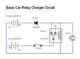
    This is the first circuit I've been testing (not an approach you recommended, but wanted to rule it out):


    This time the coil worked. In fact, disconnecting the coil turned off the circuit. But the results were mixed. The neon does not light in test mode.
    I think you will have less output power than your previous circuit because you are now adding both coil in series. The power of this kind of circuit is directly related to your coil impedance. Low impedance = higher output power. Notice that my circuit connect the car coil to battery positive and negative directly upon ON condition.

    Originally posted by Godfrey View Post
    It's difficult to measure results. Got any tips for detecting radiant spikes?
    Some use scope, some use a neon bulb:
    YouTube - Single coil stingo lighting up neon bulb

    Comment


    • #17
      Hi Sucahyo,

      Thanks for your post!

      The resistor value need to be changed according to application. I use it for many application. But all the position is settled. The output diode also depend on application. I do not use any if I just want to produce spark.
      Yes, I saw your discussion on another board about using it as a zapper. I’m very interested in talking to you about the health results you’ve experienced, but perhaps that’s too much of a digression, at the moment. for the subject of this thread.

      I ask because spark is hot. Suppressing spark heat usually is a problem.
      My replication of the basic Imhotep circuit does not visibly spark at all when propperly connected. I only see a spark when the charging battery is disconnected, even with the neon in place and lighting up.

      Here it is again with the modification of power going to 30/common:


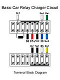
      Which works out to this on my new board:


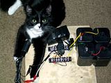
      Here is the board being hooked up by one of my lab assistants with that little SLA battery I mentioned previously. Don’t worry she doesn’t allow me anywhere near the charger when it’s actually running


      I think you will have less output power than your previous circuit because you are now adding both coil in series. The power of this kind of circuit is directly related to your coil impedance.
      Exactly so. The output would not light a neon bulb.

      Low impedance = higher output power. Notice that my circuit connect the car coil to battery positive and negative directly upon ON condition.
      I’m still learning about impedance, but won’t that increase with any coil as the size/windings do?

      Some use scope, some use a neon bulb.
      Thanks, been using that neon test. I’d love to have the budget for a good scope. My antique Heathkit one is more a paperweight than a pracical instrument

      - Godfrey

      Comment


      • #18
        Originally posted by Godfrey View Post
        Here is the board being hooked up by one of my lab assistants with that little SLA battery I mentioned previously. Don’t worry she doesn’t allow me anywhere near the charger when it’s actually running
        Some say cat can detect healthy radiant (yes it can produce bad radiant too). When you have cat around your device, you have a switching mechanism reaching MHz. Don't ignore her advice .

        Originally posted by Godfrey View Post
        I’m still learning about impedance, but won’t that increase with any coil as the size/windings do?
        You mean depend? yes. Switching car coil would give you big spark and will surely lit the neon bulb output.

        I still don't have scope too, we can reach more efficient circuit one way or another .

        Comment


        • #19
          Hi Sucahyo,

          Thanks for your post!

          I’ve just put together something like the second relay circuit you posted earlier with the capacitor and potentiometer.

          The relay coil is measuring around 90 Ohms, so I pre-tuned my 1k 15 turn trim pot to around 40. The only cap I had that is 47uF is an electrolytic rated for 200V.

          When I turn it on, the relay oscillations are high and faint, and then gradually fade off. A
          few turns of adjustment on the potentiometer don’t seem to make any difference and neither does whether the ignition coil is connected or not.

          When I leave the cap and Vr out of the circuit, the relay oscillates normally, but neither the charging battery output, nor HV output on the car coil light a neon.

          I’m starting to wonder about these cheapo car coils I picked up on eBay. Tomorrow, I’m going to attempt scavenging a MOT and test that as a comparison.

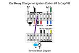
          Here is the schematic:


          And a diagram of the terminal board:


          Please let me know if you see anything amiss.

          - Godfrey

          Comment


          • #20
            Hi Sucahyo,

            Thanks for your post!

            I’ve just put together something like the second relay circuit you posted earlier with the capacitor and potentiometer.

            The relay coil is measuring around 90 Ohms, so I pre-tuned my 1k 15 turn trim pot to around 40. The only cap I had that is 47uF is an electrolytic rated for 200V.

            When I turn it on, the relay oscillations are high and faint, and then gradually fade off. A
            few turns of adjustment on the potentiometer don’t seem to make any difference and neither does whether the ignition coil is connected or not.

            When I leave the cap and Vr out of the circuit, the relay oscillates normally, but neither the charging battery output, nor HV output on the car coil light a neon.

            I’m starting to wonder about these cheapo car coils I picked up on eBay. Tomorrow, I’m going to attempt scavenging a MOT and test that as a comparison.

            Here is the schematic:


            And a diagram of the terminal board:


            Please let me know if you see anything amiss.

            - Godfrey

            Comment


            • #21
              Here is an update on my own investigations for what it's worth. I have just apparently burned out a relay. It's not completely dead, but it doesn't work for more than a second or so. It's cheap to replace and I'm glad I incorporated a harness in my setup so I just have to unplug the relay and swap it out.

              Using the normally open contact on the relay to drive a second coil has so far proved problematic. I have observed that too much of the back EMF activity is happening in the circuit, because of the voltage collapse in the relay coil, when the normally open contact actually closes. As a consequence, the current and voltage fed to the additional coil is poor. The back emf is also not being channeled very well to the charging battery and therefore causes sparking and excessive heat to happen on the relay.

              An expanded circuit that actually works may involve more that one relay. We'll see. I still would like to here from more people who have added more coils to this circuit successfully.

              The basic relay circuit has worked very well for me. I will continue to charge batteries with it. What remains its real charm is that the parts are easy to scrounge from local junk. The relays are also available at the auto parts stores as well as Radio Shack in my area.

              - Godfrey

              Comment


              • #22
                This works!

                I just revived that relay by cleaning the carbon off the contacts, though it's still acting dicy, so I'll be ordering some cheap replacements soon.

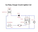
                Meanwhile, this is the final scenario I wanted to test, and it does indeed work with that ignition coil I've been using all along and suspecting. I merely used the basic relay circuit and replaced the charging battery with the car coil's primary terminals. Then I hooked up a neon bulb between the HV + output of the coil and its regular negative terminal, and it lit up very brightly when the circuit was turned on. Here's a schematic of it:


                The fact that the ignition coil fires at all has obviously got more to do with the radiant effect and high voltage than the low current being output. I haven't done more testing than that, but I intend to see if I can light a CFL next. Then, I've already fashioned a bridge rectifier to try that output on a battery. I also want to measure the current draw on the source battery, etc. I'll post more as things develop.

                This development is interesting enough. It means the relay circuit can generate HV pulses powerful enough to be the initial drive for another HV step up device. Hmmm I'm thinking Tesla Coil possibilities

                - Godfrey

                Comment


                • #23
                  Interesting progress .

                  When you lit neon bulb with high power it will turn purple. It seems the ouput is shared between the neon bulb and the car coil.


                  I don't think you can charge a battery with car coil output though because it would lack of current.

                  Contact need to be cleaned regularly. More so with more output.
                  Last edited by sucahyo; 08-31-2010, 03:38 AM.

                  Comment


                  • #24
                    Hi All,

                    Originally posted by Sucahyo
                    I don't think you can charge a battery with car coil output though because it would lack of current.
                    It lit a neon bulb brightly. I can't tell what color my neon bulbs are burning because they're the kind embedded in red plastic, so the light's red no matter what.

                    You are right, Sucahyo, car coil power output was not sufficient to light a CFL

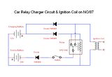
                    But here is the circuit that I think should work for adding a big coil:


                    I've got my test board all setup so it's easy to add a coil or just use the basic car relay circuit, which should not mind the extra diodes. They seem to help, however, when a coil is added by stabilizing the current flow and directing Back EMF from both auto and relay coil properly to the charge battery.

                    That said, I'm having problems with the relays I just bought and so have not tested extensively.

                    I'm also going to add the cap and pot across the relay coil again to experiment with Sucahyo's method to control frequency. It still resembles an RC coil snubber to me, and therefore must clamp/dissipate some of the back EMF coming from the relay coil.

                    I also just picked up the other relay from the parts list for Imhotep Lite/CFL circuit. I'm going to see if this 9v relay, with a 500 Ohm coil and contacts rated for house voltage/current behaves better when driving an ignition coil as appears to be the case so far from the replications others have done. The car relay's small 90 Ohm coil may be the cause of some of the problems I've been experiencing with some of the circuits I've tried and documented here.

                    I will post any interesting developments and still encourage others to chime in with their own relevant findings.

                    Godfrey out.

                    Comment


                    • #25
                      Originally posted by Godfrey View Post
                      It lit a neon bulb brightly. I can't tell what color my neon bulbs are burning because they're the kind embedded in red plastic, so the light's red no matter what.
                      When the output voltage increase, it can light purple too:
                      YouTube - Purple flashing show off


                      Originally posted by Godfrey View Post
                      But here is the circuit that I think should work for adding a big coil:

                      My relay would never turn on the car coil with that configuration. That is the reason I add capacitor and resistor. To allow longer relay on time.


                      Originally posted by Godfrey View Post
                      The car relay's small 90 Ohm coil may be the cause of some of the problems I've been experiencing with some of the circuits I've tried and documented here.
                      My ohmmeter messed up so I can not measure my car coil impedance, but I remember it to be smaller than 10 ohm. Brand is Mallory pro.

                      Comment

                      Working...
                      X