Announcement

Collapse
No announcement yet.

Stingo Solid State Battery Charger

Collapse
X
 
  • Filter
  • Time
  • Show
Clear All
new posts

  • 1.5V Stingo Lights Neon!

    Here are my latest test results.

    Originally posted by Godfrey View Post
    I haven't given up on Coily yet, so today as we speak, I'm in the middle of changing out my transistors for two fresh ones and then will test the old ones on my meter.
    So, I swapped out the transistors in my Stingo. And I tested my old TIP2955 and TIP3055 transistors on my multimeter with the hFE function:
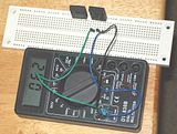


    The NPN test made sense. I got an hFE reading of 062, which fits the spec, but the PNP measured 125, which doesn’t make sense spec-wise, given that the DC current gain should fall between 20 and 70. But the readings I got for brand new ones were very close to the readings I got, measuring 069 for the NPN and 129 for the PNP. So I’m concluding they are ok, and not about to blow.

    Based on what Sucahyo has been recommending lately, I also decided to pair a TIP32C with a TIP3055 for the replacement transistors.

    My 12V tests with Toroid coil and Car Coil yielded results identical to my previous ones. It just helped clarify things. I think that the toroid coil would make a respectable 12V battery charger, given it lights a neon brightly.

    Originally posted by skaght View Post
    I just started playing with the stingo and got it to work with a 3906 PNP and a C6081 NPN. It worked with a single 1.5 volt battery…
    Inspired by JiffyCoil’s and Skaght’s 1.5V results, I decided to run a 1.5V battery test with the toroid and was pleasantly surprised to see it oscillate well and light a neon bulb:
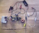


    Here is a scope shot sampled from the PNP base, which shows oscillation of about 1KC:
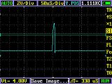


    Here is a scope shot sampled at the output, showing very sharp, 90+V spikes. The duty cycle is about 1.2 %:
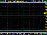


    Now to catch up on what has thankfully become a very lively thread!...

    - Godfrey

    Comment


    • Originally posted by 7imix View Post
      It's 32 awg magnet wire. I only did one layer, but now I'm thinking I should do as many layers as I can fit in there, after seeing Godfrey's toroid.
      My preference would be to use something a little meatier, like 22-26 gauge. The weaving shuttle winding method makes fold kinks that have to be worked out later as you wind. I tried 32 gauge, but had problems with its delicateness. It kept breaking on me.

      Comment


      • Originally posted by skaght View Post
        Oh, and I did have to raise the base resistor from the 10k pot up to 47k ohms to get it to oscillate...
        Thanks for your posts, Skaght! Which coils did you have to do this for? I tested a few with a 50K pot myself.

        Comment


        • Originally posted by Jiffycoil View Post
          I wanted this build of the Stingo to have the complete ability to change out components with relative ease. I'm using TIP41A and TIP42A on the build now. I tested the build to make sure it working properly by powering a small pancake coil and at 5 volts 50mA I was getting 68 volts from the out put leads. I will now be able to start detailed testing. Thanks to everyone for your help and suggestions...
          Nice job JiffyCoil! Looks like a very flexible setup. Love the heat sinks...they remind me of spoilers.
          Last edited by Godfrey; 11-14-2010, 09:17 AM.

          Comment


          • Originally posted by cikljamas View Post
            Here is my new video, you can see my "almost OU", and help
            with advices how to make that one step more :
            YouTube - one more step.avi
            Nice work Cikljamas & good presentation...all the way up to "how you turn this off?",

            Very interesting results! With the cap connected to the output, charged to 80+V you are indeed already OU+!

            Dumping it to a charge battery should not be too tricky, but dumping it back to the source battery…problematic. Would like hear what others say about that.

            Comment


            • Originally posted by 7imix View Post
              I did some experiments with my original stingo sparker and the pancake coil I just built.

              With the high voltage output hooked up to the coil primary and the spark gap, and one side of the fluorescent bulb hooked up to the center tap of the bifilar coil, the fluorescent lights. One wire transmission.

              The stingo produces the correct shape impulses without the spark gap, too, and in the second part of the video I show the fluorescent lighting without the gap sparking.

              YouTube - one-wire
              Wow! Really interesting setup and one wire transmission results, 7imix!

              There doesn’t look like a lot of windings involved in that pancake coil, especially the primary... bifilar huh? Got any specs on the resistance & henrys?

              Is that little fluoro a cold cathode tube?

              Originally posted by sucahyo View Post
              You mean stingo produce spike without a backspike ?
              Originally posted by 7imix View Post
              Yes. It produces a little backspike, but compared to the magnitude of the upspike it's almost nothing.

              Except since in the radiant recovery part of the circuit the leads are reversed, what I'm describing actually is the backspike... but from the reversed perspective it looks like an upspike...
              Take a look at that output scope shot I just posted. It illustrates exactly what 7imix is talking about. I hooked the positive lead of the scope to the radiant positive output and the negative lead to the radiant negative (battery positive, due to reverse spike).

              The top of the spike goes off my 10V scale, but you can see that it is almost all positive, except for a little joggle at the end, making it ideal to use as an HV input impulse, as 7imix has so well illustrated.
              Last edited by Godfrey; 11-14-2010, 11:05 AM.

              Comment


              • Simplest Stingo Circuit

                Originally posted by Farmhand View Post
                ...Could you please point me to your most recent, and most basic Stingo please, I should build a basic one first I think.

                I might understand him better that way.
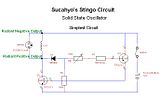
                Hi Farmhand, thanks for participating! Here is the basic Stingo circuit that got me going:


                - Godfrey
                Last edited by Godfrey; 11-14-2010, 01:03 PM.

                Comment


                • Originally posted by Godfrey View Post
                  Nice work Cikljamas & good presentation...all the way up to "how you turn this off?",

                  Very interesting results! With the cap connected to the output, charged to 80+V you are indeed already OU+!

                  Dumping it to a charge battery should not be too tricky, but dumping it back to the source battery…problematic. Would like hear what others say about that.
                  Well, i succeeded to measure mAmps before my last meter was busted :
                  input : 23 mA
                  output : 20 mA
                  Now if we count 80 V output comparing 12 V input it should be OU
                  because 20*80 = 1600 and 23*12 = 276, so 1600 > 276, but somehow
                  it does not work like that...P = U x I, but...2 x 2 is not always 4...
                  I need something like this :
                  webcafe.hr - forwarduše / video
                  to jump across that barrier, but maybe
                  we should first have to know what is this barrier ???

                  all the way up to "how you turn this off?"
                  It is interesting story how it happened but i ll tell you that story some
                  other time...In the meantime enjoy my clumsiness !
                  "There is no love without prayer - there is no prayer without forgiveness because love is prayer - forgiveness is love." Virgin Marry - Immaculate Conception ...The geologists say it's not in the ground, the airforce says it's not in the air, the astronomers say it's not from space, so we are running out of options...

                  Comment


                  • I must give stingo the credit : with just two stingos and three coils
                    i achieved 60 % of efficiency : input 320 mA---output 190 mA...
                    It is now better then my bedini 4 coils which result is : input 380 mA,
                    output 190 mA...Sucahyo is better in electronics than Bedini is !!!
                    Did you know that ???
                    Now, what is left to do is to be better then Waykykjy (if i good remember
                    his nick)...Lets get ready to rumble !!!
                    Let me see your hands...
                    Sing with me : We shall overcome...
                    I dont hear you...Louder, please !
                    Sucahyo, do you believe it is possible ?
                    What do you say about my calculations in my previous post ?
                    What is the catch 22 in OU case ?
                    Just to replicate someone elses already existed project or to always
                    discover hot water from the beginning as one croatian byword says ?
                    And if someone want to know, why we try to achieve OU , than we
                    should answer as alpinists do when someone ask him why they climb
                    difficult climbs : BECAUSE IT IS THERE (MOUNTAIN) or in our case OU!!!
                    Dont you think so ? All alpinists want to climb Mt. Everest, isnt that
                    the same with us who are in love with electronics ? So, how come we
                    are not already there ? I can not bear that some guy in South Africa
                    has such a beautiful project locked ih his drawer and we know that
                    he has it but such a huge number of other people cant replicate it...
                    It is for Ripleys believe it or not !!!
                    "There is no love without prayer - there is no prayer without forgiveness because love is prayer - forgiveness is love." Virgin Marry - Immaculate Conception ...The geologists say it's not in the ground, the airforce says it's not in the air, the astronomers say it's not from space, so we are running out of options...

                    Comment


                    • Thanks for the transistor tips everyone .


                      Originally posted by skaght View Post
                      I'm running my stingo/slayer (I've dubbed it the Sting-slay) combination circuit and charging a lead acid battery at ~500 kHz. It has an h shaped output on my scope, and the transistors are both cold--I can't detect any heat from either NPN or PNP.
                      That a very high frequency . thanks for the h shape info .

                      Originally posted by cikljamas View Post
                      Well, what i tried is two stingos and three coils (i wound third one) and i think this is absolutely ok for the purpose that i need this, and not just that, i combined it with bedini ssg, and what we got, let see in my new video...
                      YouTube - stingo bedini 1
                      I shot this video two hours ago, and there is still no discharging of my
                      primary battery...weird...
                      Very interesting result . Primary that driven stingo and secondary that driven bedini is self charging too . And you get the primary increase voltage instead of getting discharged. That is awesome .

                      I think lead acid is the key to get your result. We may not have same result with SLA.

                      Originally posted by Godfrey View Post
                      Inspired by JiffyCoil’s and Skaght’s 1.5V results, I decided to run a 1.5V battery test with the toroid and was pleasantly surprised to see it oscillate well and light a neon bulb:
                      Nice . I want to be able to do it too....

                      Originally posted by Godfrey View Post
                      Here is a scope shot sampled at the output, showing very sharp, 90+V spikes. The duty cycle is about 1.2 %:

                      ...

                      Take a look at that output scope shot I just posted. It illustrates exactly what 7imix is talking about. I hooked the positive lead of the scope to the radiant positive output and the negative lead to the radiant negative (battery positive, due to reverse spike).

                      The top of the spike goes off my 10V scale, but you can see that it is almost all positive, except for a little joggle at the end, making it ideal to use as an HV input impulse, as 7imix has so well illustrated.
                      Thanks. I found that very interesting . NO backspike should be usefull for spark experiment ....


                      Originally posted by cikljamas View Post
                      Well, i succeeded to measure mAmps before my last meter was busted :
                      input : 23 mA
                      output : 20 mA
                      Now if we count 80 V output comparing 12 V input it should be OU
                      because 20*80 = 1600 and 23*12 = 276, so 1600 > 276, but somehow
                      it does not work like that...P = U x I, but...2 x 2 is not always 4...
                      I measure it like this:


                      COP = (output voltage * output current) / (input voltage * input current)


                      However, I think we should prepare too that it give too unbelieveable result, this is example of what look like a COP = 10 result, using the circuit above. But I doubt it really COP>1, maybe the meter is just fooled.
                      YouTube - stingo 3V charge 3V cop 10?

                      The video show 3V charging 3V, where the input current is 420mA and the output is 4000ma if I touch the wire.

                      Originally posted by cikljamas View Post
                      I must give stingo the credit : with just two stingos and three coils i achieved 60 % of efficiency : input 320 mA---output 190 mA... It is now better then my bedini 4 coils which result is : input 380 mA, output 190 mA...Sucahyo is better in electronics than Bedini is !!!
                      No, stingo is just a derrivative of Bedini circuit . Begini get more awesome result .


                      Here is another trick to try to get COP>1 with stingo. This trick require circuit that reduce consumption with load, like stingo.

                      The trick is to reduce load impedance.

                      I think some of you already experience getting higher amp out than in. I notice that happen if I charge 3V battery with 12V source input. We get lower amp out if we charge 12V battery. What is the difference?

                      Impedance. 12V is 6 cell of 2V. In order to get lower impedance from 12V battery, we should parallel them. By paralleling load battery, we get lower impedance and hopefully get higher amp output too.

                      example, with rough number
                      2 nicad impedance = 0.7 ohm
                      6 lead acid impedance = 5.4 ohm

                      How do we get 0.7 ohm impedance with 12V battery?
                      6 / 0.7 = 7.7

                      we need 8 battery to get nicad impedance.


                      If we use 12V source, we use more 12V battery at load in parallel. The conventional measurement result would then get us COP>1 . Is it a valid COP>1 or not? who knows. I don't have many battery......


                      The usual trick to parallel the load and series the source can also work too.


                      To get more impressive result using above COP calculation, measure when the load battery is full .


                      But for the real COP > 1, I think cikljamas has done it .
                      Last edited by sucahyo; 11-15-2010, 02:21 AM.

                      Comment


                      • Hi all, My Stingo finally works , Here I have a couple of picture's.

                        Stingo Sulute.
                        http://koyg9g.bay.livefilestore.com/...ute.png?psid=1
                        Stingo Waving to Sucahyo
                        http://koyg9g.bay.livefilestore.com/...ing.png?psid=1
                        Stingo is charging a battery for me first, I used an old quadfiler coil I had only using one winding through a bridge to charge battery, he works very good. 250 Ma min draw and more than 600Ma max, haven't warmed him up yet.

                        Unfortunately I have to go on a short work trip, maybe a couple of days, not sure when I will go yet. I'll try to keep up by wireless, but it may not work very well.

                        Regards

                        I forgot to say thank you to Godfrey for posting the basic Stingo drawing for me, it helped a lot.
                        Last edited by Farmhand; 11-18-2010, 03:55 AM. Reason: Fixed links

                        Comment


                        • Originally posted by Farmhand View Post
                          Hi all, My Stingo finally works , Here I have a couple of picture's.

                          Stingo Sulute.


                          Stingo Waving to Sucahyo


                          Stingo is charging a battery for me first, I used an old quadfiler coil I had only using one winding through a bridge to charge battery, he works very good. 250 Ma min draw and more than 600Ma max, haven't warmed him up yet.

                          Unfortunately I have to go on a short work trip, maybe a couple of days, not sure when I will go yet. I'll try to keep up by wireless, but it may not work very well.

                          Regards
                          Congratulation . Thanks for the wave shot .

                          That picture make me wonder if we will get that kind of wave on whatever frequency when charging? Because obtaining that kind of wave only appear at spesific frequency in SSG? Anyone can confirm?


                          Good luck .

                          Comment


                          • Originally posted by sucahyo View Post

                            No, stingo is just a derrivative of Bedini circuit . Begini get more awesome result .
                            Which bedini circuit? I haven't built any bedini circuits, I would love some pointers to which circuits are good to try building.

                            Comment


                            • Originally posted by 7imix View Post
                              Which bedini circuit? I haven't built any bedini circuits, I would love some pointers to which circuits are good to try building.
                              The beginning, Bedini monopole or SSG.

                              Comment


                              • I do some modification to the FWBR combiner. But, I don't know if this will improve anything. It is just an accumulation of what I thought to be the best configuration. The reason:
                                - to combine radiant circuit output
                                - to also capture coil back spike
                                - prevent the source from powering the load directly, only a brief moment after the spike (capacitor provide the bouncing)
                                - diode from source negative allow possibility to charge the source


                                I use only two stingo for my charger:


                                The output so far is about the same as previous circuit. Since the capacitor only block the current from battery, the stingo see the load as higher impedance load and thus draw less current.

                                Comment

                                Working...
                                X