Announcement

Collapse
No announcement yet.

Don Smith A review...

Collapse
X
 
  • Filter
  • Time
  • Show
Clear All
new posts

  • @ ilandtan


    just to add something here, in practice there's a lots of parameters, like a simple battery and light bulb circuit


    a simple switch will cause the bulb to light up, the same switch will cause it to be in off state, here you still have the power but the switch in off state, the same thing may happen to us, in some test i just changed a thin wire with another thick wire and the power increased dramatically in the capacitors banks, you know about skin effect, i too, but sometimes we do the bad thing by making the switch in off position and we say this don't work !!!!

    i am telling this to say there's a lots of critical parameter that we must notice to achieve a power gain! we have to make sure the switch is in ON POSITION !

    Comment


    • So what is the mechanism for power gain here. According to DS it is "simply" exciting magnetic resonance at RF, and that spin change creates gain, is that correct? Did I miss something?

      Comment


      • Originally posted by ilandtan View Post
        So what is the mechanism for power gain here. According to DS it is "simply" exciting magnetic resonance at RF, and that spin change creates gain, is that correct? Did I miss something?

        Hello ilandtan,

        there's a paradox in DS device, this is why we fail i replicating his device, one friend told me that i am focusing in the capacitor because i concentrate on using conducting foils rather than using normal wire,... but the E-TBC isn't a coil neither a capacitor.. it's both of coil and capacitor! ok what happen when we use normal parallel L/C circuit ?


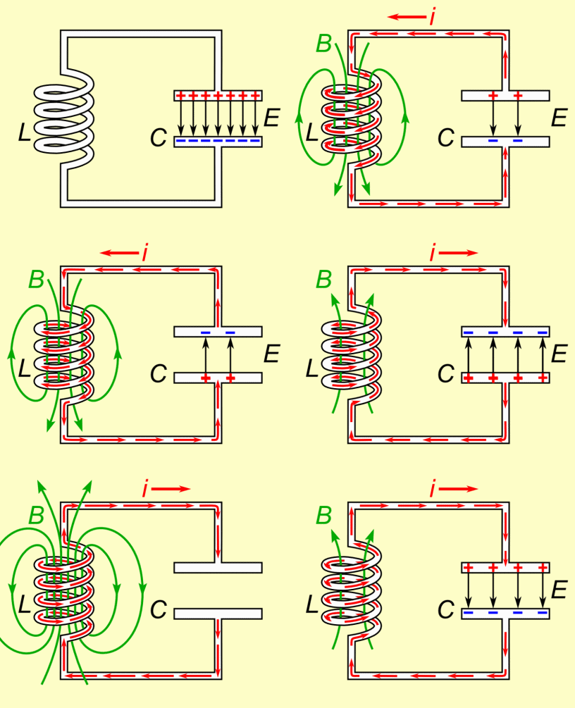
        in the above case you are replicating your signal ( information) because you have a coil plus capacitor there's a phase shift between voltage and current ( reactive power ), in this case if there's no loss of any kind this oscillation may stay forever ... but as you know dumping oscillation will happen and the oscillation will die very soon.


        in the E-TBC the Mechanism of power gain is the increased oscillation, this is a scope graph from an oscillating E-TBC :

        using the following simple schematic :


        if you are able to maintain the voltage high the increased oscillation will take a long time than the above graph, in this case you need a spark gap to limit the voltage and protect your system... in fact you need a very little power to maintain the oscillation high but you need a kind of resonance between the e-tbc and another capacitor, so you are sure you have a high voltage between A and B most of the time, without resonance as the above test the high voltage will die due to the little resistance, adding another capacitor to achieve the resonance with your high voltage power source will protect this voltage from dropping, exactly like a bouncing ball ... the higher altitude the more the ball bounce :


        after that the E-TBC will do the job, this device isn't only a parallel L/C, it also combine a serial L/C, i can't explain this because it's a quantum phenomena related with electrons spin changing mechanism or electrons separation mechanism, this is possible and easy regarding the geometry of the E-TBC because the CCW foil front of your eyes is CW in behind !! the electrons just need to relax and spin back .... because it's still an open circuit this is very easy in fact !

        Comment


        • I'm still not clear where you are getting more power Med. If you keep a closed system oscillating, at a high voltage, it is doing so at the limits of the input power. I also am not familiar with the E-BTC, can you point me to its documentation?

          Comment


          • Originally posted by ilandtan View Post
            I'm still not clear where you are getting more power Med. If you keep a closed system oscillating, at a high voltage, it is doing so at the limits of the input power. I also am not familiar with the E-BTC, can you point me to its documentation?


            Hello!


            Thanks for your contribution, in reality we have a lots of options to deal with the capacitor, about the E-TBC here you are my document http://free-energy-info.com/Mohamed.pdf

            the idea is to find the power in one point not between two point like ordinary coil, this is why it's better to use conducting foils, if you are able to oscillate this device correctly you will be able to replicate your power thousand of times... when you see the foils you think you are working with electricity not magnetism but this is not correct! and this is the paradox in this device, i did a mistake in my document as stated before the junction CD must be closed because it's the path for electric current, this system is not a closed, it's an open system able to attract electrons with radio frequency speed, now the problem it's not easy to manage this system this is why i am thinking about other methods where we could charge a relatively low voltage capacitors ( around 450 V) since this is the most practical voltage we could work with.

            Comment


            • Med thanks for the link and information. I love reading where people start trying to understand the mechanics of DS devices, and thus enumerates our one sided view of electricity and magnetism. The two coils wound in opposite directions remind me of the phase conjugate stuff I hear about helpful plasmas or Russel's cones. Also the coils can be switched out with copper pipe and you get a Tesla hairpin circuit, something Tesla dragged to every show. Med do you have any videos of what you have built and a summary of how far you have come?

              Comment


              • Originally posted by ilandtan View Post
                So what is the mechanism for power gain here. According to DS it is "simply" exciting magnetic resonance at RF, and that spin change creates gain, is that correct? Did I miss something?
                You have 2 parts: exciter and the antenna.
                The exciter umbalances the ambient background spins.
                The antenna absorbs energy from the ambient background spin.
                There is no gain in the system. There are different systems that use an antenna to absorb energy from the background. DS uses an exciter to umbalance those spins.

                I have been using a Barbosa circuit and you can see very easy how there is an umbalance in the background spins when you switch on the circuit. You can see how the transformer in some cases uses no wattage and there is a strong umbalance in the ambient background (magnetic materials start to vibrate a lot).

                Comment


                • Originally posted by med.3012 View Post
                  Hello ilandtan,

                  there's a paradox in DS device, this is why we fail i replicating his device, one friend told me that i am focusing in the capacitor because i concentrate on using conducting foils rather than using normal wire,... but the E-TBC isn't a coil neither a capacitor.. it's both of coil and capacitor! ok what happen when we use normal parallel L/C circuit ?
                  Smith observed something that is not commonly known and it's in the coils. The people usually don't see that I don't know the reason because it's enough clear in the diagrams.

                  There are multiple factors in the resonant circuits and lots of different versions.

                  If you want to understand DS device, you must to perform a lot of experiments with RLC an LC circuits. Smith system is a second generation RLC circuit.

                  A lot of people is trying to perform experiments without understanding the main concepts.

                  Comment


                  • If you want I can show you both how it's possible to light an incandescent light bulb with the air as the power source (no batteries, no energy from the socket, etc...).

                    Comment


                    • Originally posted by ilandtan View Post
                      Med thanks for the link and information. I love reading where people start trying to understand the mechanics of DS devices, and thus enumerates our one sided view of electricity and magnetism. The two coils wound in opposite directions remind me of the phase conjugate stuff I hear about helpful plasmas or Russel's cones. Also the coils can be switched out with copper pipe and you get a Tesla hairpin circuit, something Tesla dragged to every show. Med do you have any videos of what you have built and a summary of how far you have come?
                      you are welcome, i am planning to produce more videos but i am busy at the moment with some tests, you are right about using a toroidal arrangement because it's the best way to ensure the best electromagnetic feedback inside the E-TBC, it's also possible to use a bifilar arrangement but it's better to use conducting foils to collect ambient electrons, so we could achieve the needed increased oscillation.

                      i noticed this when i tested a large turn number E-TBC in high voltage, i was able to see the effect of increased oscillation but i failed in the mixed E-TBC, more test have to be done for the final conclusion, i can't tell exactly how far i am reaching at this moment because we need a proof ... if you want to try something i suggest you to start directly with toroidal system, you could start with the mixed E-TBC if you like since it's two E-TBC, how you build the E-TBC on a toroid ferrite? like any bifilar coil just use foils instead of normal wires, you could use two turn in a place and move the half of foil width so the next turns is relatively over the first .. etc ... with the other turns, it's better to wind your bifilar coil all along the toroid circle, just count your turn number for example you made 10 in the primary, the secondary have to be 40 turn, now make the same for another toroid core, make sure to connect the two E-TBC as to form a mixed one... you need to concentrate with a ferrite as a core you will achieve around 1000 more feedback inside your primary ... in other hands greater current will be induced in the secondary, the only problem is the reduced frequency, for sure there's an optimal values we have to work with but it's great if you test this and tell us the results.. so we could compare our works and see the weak point and the strong points also !

                      regards

                      Comment


                      • Originally posted by AetherScientist View Post
                        If you want I can show you both how it's possible to light an incandescent light bulb with the air as the power source (no batteries, no energy from the socket, etc...).
                        hi AetherScientist !


                        welcome back, for sure i want to see this

                        Comment


                        • Originally posted by BroMikey View Post
                          I reply each part
                          In almost any Tesla coil video I have watched on the web for
                          the past 15 years always shows the power going up in both.
                          What do you exactly mean? I have seen that when you approach one L2 to the Tesla coil, then the end of the additional L2 starts to emit some sparks.

                          Thanks for the reminder, I just watched the D.S. video's again in
                          Dec 2014 and this is what he says.

                          If you do find a video of a Tesla coil operating with an amp meter
                          on it the primary draw current will climb as excessive power demands
                          rise. Forcing these tune-able circuits into heavy load conditions
                          will indeed bring about a 1:1 relationship at some point.

                          What DON did was tune as you say for a phase angle shift while
                          in resonance
                          that pumps energy around the transmitters circuit.
                          As an example of reactive power THANE HEINS has devoted much
                          time to showing how 3 coils can be tuned for a phase relation
                          where the input power and output power are 90 degrees out of
                          phase.
                          How he accomplished that? Explain in detail that part.


                          This means that most conventional thinkers with great abilities
                          are tuning their coils in phase because they don't know any better.
                          It is this group of conventional techy's that we have to work with
                          as they are able to work all of the tools.

                          When the people finally do catch on to what you are saying this
                          field with begin to change very rapidly.
                          Again, how it is possible to tune the L2 coil in resonance AND 90º out of phase?


                          I have learned it takes a delicate balance to keep the transmission
                          winding reactive without over drawing power off the secondaries but
                          once this condition is reached you may load the secondary from
                          0-10 within the design range.

                          Even the most advanced have stated that they tried it and it is
                          impossible. This includes everyone who has ever come to this
                          forum and all other forums on the web since the internet began.

                          I have never heard any well known name say they have it working.

                          Yet DON SMITH did it. And I believe he did.
                          How do you think he accomplished that?

                          Comment


                          • Originally posted by med.3012 View Post
                            hi AetherScientist !


                            welcome back, for sure i want to see this
                            Hello again

                            Ok, I take note and I will make a video.

                            Comment


                            • Welcome back AS!

                              Comment


                              • Originally posted by ilandtan View Post
                                Welcome back AS!
                                Thank you

                                Comment

                                Working...
                                X