Announcement

Collapse
No announcement yet.

Don Smith A review...

Collapse
X
 
  • Filter
  • Time
  • Show
Clear All
new posts

  • #91
    AetherScientist,
    This is an interesting development which parallels something I discovered in the last few days.

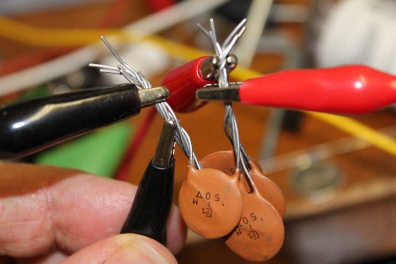
    I am not using a car ignition coil, and so am dealing with relatively low voltage. Still I was having the same problems with extracting useable power from the caps, which were charged from an AV plug. Here is the start of my solution:

    I decided to take six small (50pf) ceramic caps and charge them in parallel and run them to an LED light. The light began to glow.

    Then, I ran a ground wire to the negative terminal of my lead acid battery powering the circuit, and my voltage at the bulb doubled.

    I will keep experimenting.
    Bob

    Comment


    • #92
      Hi Bob,
      Very good observation.
      You say that you're not using a car ignition coil to feed the AV plug. So, what are you using instead the ignition coil?

      I want to experiment with a special capacitor configuration having multiple plates instead of just only 2 plates. It seems that it's possible to mix different electrical characteristics. It's possible to run a device using 1 plate, 2 plates or 3 plates capacitor.

      1 plate = open capacitor
      2 and or 3 plates = closed capacitor

      It would be interesting to build a mini tesla coil and try the same experiment. Using the HV output (single wire) from the mini tesla coil and feed an AV plug to a capacitor. Then attach the negative from the battery to the AV plug and see what happens with that capacitor when you try to light a small bulb.

      Comment


      • #93
        Originally posted by AetherScientist View Post
        Of course, there is a lot to say about that circuit. That is the same principle Smith is using in the amplifying part. The same principle as you're using. It's good to know that you can obtain energy from that configuration.

        Can you describe better what are you doing there?
        I am still reading your pdf document where you speak more about the E-TBC


        Hi AetherScientist,


        the idea is to avoid using CD connection in the E-TBC as a source of resonance, so we have to close it as described in my thread, we have to treat this device as a single entity, so i did a mistake in my PDF, the same apply to the mixed E-TBC where the spark gap must be outside the system as the following drawing :


        Attached Files
        Last edited by med.3012; 12-18-2015, 10:40 AM.

        Comment


        • #94
          the experiment details , just using two E-TBC that work reversely, one as black E-TBC the other is the red E-TBC, if one produce current the other will produce voltage and vise versa, each E-TBC is composed from two aluminum plate with 70 cm length, the width is 6 cm, upon construction they have to be identified, for example using red wire for the positive plate and black for the negative plate, as you see in the drawing the upper plate in the red E-TBC must be the positive plate, the same apply about the black E-TBC where the upper wire have to be the negative plate, it's simple,

          the two plate was treated chemically, etching process so just to achieve more capacitance maybe X 3 more area, about the length of L2 coil i used 5.6 m in each side, 0.7+0.7 = 1.4 x 4 = 5.6m.


          edit etching process is an option only, i did it for testing purpose, not etched foils will work just good !
          Last edited by med.3012; 12-18-2015, 11:28 AM.

          Comment


          • #95
            Hello med.3012 and hello to everyone
            I will answer to your posts later, but I write this post because I have observed a very similar behaviour to your drawinng while observing a different thing.

            The main question has been... Why Smith charges his capacitors with 3 wires instead of 2 and why he uses diodes only in the positive wires and not in the negative?

            I'm drawing a few explanations. I don't know if I have enought time to do it in 30 minutes, but if I don't finish the drawings now I will finish it in a few hours.

            Comment


            • #96
              This is the configuration I was observing and trying to know why Smith used that configuration. The explanation is long and it's related with a scalar potential mixing system.

              Comment


              • #97
                As you know, Smith said that one component spins CW and the other component spins CCW. In the center you have the cancellation of the 2 components. But when you sum the 2 components you have also a cancellation.
                I explain all this later.

                Comment


                • #98
                  Originally posted by AetherScientist View Post
                  As you know, Smith said that one component spins CW and the other component spins CCW. In the center you have the cancellation of the 2 components. But when you sum the 2 components you have also a cancellation.
                  I explain all this later.

                  Ok i will be waiting for your explanation.

                  Comment


                  • #99
                    Originally posted by AetherScientist View Post
                    Hello med.3012 and hello to everyone
                    I will answer to your posts later, but I write this post because I have observed a very similar behaviour to your drawinng while observing a different thing.

                    The main question has been... Why Smith charges his capacitors with 3 wires instead of 2 and why he uses diodes only in the positive wires and not in the negative?

                    I'm drawing a few explanations. I don't know if I have enought time to do it in 30 minutes, but if I don't finish the drawings now I will finish it in a few hours.
                    AetherScientist
                    My time is also limited at this moment, but I will offer a guess on why DS uses the diodes only on the positive:

                    It may have something to do with cold electricity. While hot electricity flows from positive to negative, I believe CE flows in the opposite direction. Hot electricity observes the bias of a diode, but CE does not work well with diodes. In fact, CE treats resistors more like diodes. I believe that diodes, in fact, will largely kill the flow of CE.
                    I hope this helps.
                    Bob

                    Comment


                    • I am starting writting the explanation and drawing the graphics at the moment. It will take time and I will post here. Maybe 30 minutes or more.

                      Comment


                      • i just finished a few tests on my system, changing the capacitor banks with another no polarized 2UF capacitor, the performance is even greater, at this stage the circuit seem to be dangerous ... CAUTION

                        after that i tried to added another serial diode 4X HER 308 / 1000 v ( fast diode ) as described in the following drawing


                        but the performance go to near zero !!!! almost no output !!! i didn't believed what happen ... i though the diode is broken ( short circuit ) i tested them and tried again the experiment with/without diode the same thing happen more diode in just one side kill the power ...

                        anyone interested in replicating this is welcome, i will offer any required info,
                        Attached Files

                        Comment


                        • So, we ask the question again.
                          Why this circuit and why not other configuration?


                          There are different ways of analyzing this circuit, but I will show what I have observed.

                          Ok, Smith said in different occasions that there are 2 components and each one spins in a different direction, CCW one, CW the another.
                          He shows this graphic in his book:


                          (I will post little by little because this will take time). I am preparing the second post at the moment.)

                          Comment


                          • Looking in other publications, we can find that other authors explains something similar:


                            So we can think that Smith is not the only one that has observed a similar behaviour in magnetics.

                            Even science speaks about this phenomenon

                            Comment


                            • i agree with you but i think it's a good idea to analyze this phenomena regarding further experiment, i guess there is something valuable is hidden here, Donald Smith explain this in one of his old video: you have to separate the electrons and after that you need to assemble them together so you have useful electric power, energy production and then energy extraction .


                              adding more diodes to just one side affect greatly the output, equilibrium is important here... understanding this may help in increasing the performance of this system .. who know !
                              Attached Files

                              Comment


                              • Originally posted by med.3012 View Post
                                i agree with you but i think it's a good idea to analyze this phenomena regarding further experiment, i guess there is something valuable is hidden here, Donald Smith explain this in one of his old video: you have to separate the electrons and after that you need to assemble them together so you have useful electric power, energy production and then energy extraction .

                                adding more diodes to just one side affect greatly the output, equilibrium is important here... understanding this may help in increasing the performance of this system .. who know !
                                I was doing some tasks, so I stop posting new posts. I'm writting a new one and you've wrote a very interesting thing:

                                " Donald Smith explain this in one of his old video: you have to separate the electrons and after that you need to assemble them together so you have useful electric power, energy production and then energy extraction. "

                                It's the same idea that I got before reading your post. So the next post I will explain what I think and you will see how is exactly the same that you have written in your post about "after you need to assemble them". I will take some time to write the post, but I have started now.

                                Comment

                                Working...
                                X