Announcement

Collapse
No announcement yet.

Don Smith A review...

Collapse
X
 
  • Filter
  • Time
  • Show
Clear All
new posts

  • Originally posted by ilandtan View Post
    It seems that in the Don Smith recipe there are some key ingredients:
    • Electromagnetic Disturbance of the Ambient using HV (pulsed DC)
    • Magnetic NOT Electrical Resonance
    • RF band of operation preferably above 20K
    You can also use HF AC.
    It has been shown that you can feed L1 with HF AC to feed the L2 and get sparks in L2.

    Comment


    • Originally posted by AetherScientist View Post
      You can also use HF AC.
      It has been shown that you can feed L1 with HF AC to feed the L2 and get sparks in L2.
      AS - I am glad you correct me, because I welcome the opportunity to learn. However I am not sure about HF AC. Again it's my intuition but I believe there was a reason Tesla stopped trying to work on HF AC, and started pulsing DC. And I am not sure why, but the impact of a pulse creates these scaler properties. Let me ask this question, when you throw a spark gap across a tank circuit, is the output of the spark AC or DC? A lightning bolt is a DC discharge, one direction of current flow. Look at DS simple exciter>spark>capacitor plates>spark>ground it was clearly pulsed DC verbalized.

      I think you want to pulse DC. And in my opinion, the first mistake in many builds of DS magnetic resonant coils.
      Last edited by ilandtan; 01-03-2016, 06:12 PM. Reason: added magnetic to resonant coils

      Comment


      • Originally posted by AetherScientist View Post
        Where did you read that?
        Around 3:24 He did say 60WattVolt, he may of just meant 60 Volt

        [VIDEO]https://www.youtube.com/watch?v=J3Y5qMHfB_s[/VIDEO]
        Last edited by ilandtan; 01-03-2016, 06:05 PM. Reason: Clarification

        Comment


        • Originally posted by ilandtan View Post
          I agree no spark between the towers... They are transmitters. Receivers would be a home with a tuned receiver, a car, a plane. The spark I am referring to is either on the primary and optional spark in the secondary of the transmitter. After 1897 a spark was not required in the L2 because Tesla started using the slow wave helical resonator, the extra coil:Corum. Spark in the receiver was rare in the circuits I've seen and maybe limiters? Spark in the primary of the video was important because it is an electron avalanche. By definition, a spark is over unity because it causes free electrons to flow. You have gain at the spark on both sides on the plate cap, and the ambient is contributing through the casimir effect according to DS.

          Didn't Wardenclyffe use spark gap in the primary? Tesla coils always used spark gaps did they not? So when I view the Tesla coil circuit, I am looking for a spark gap outside a parallel tank of L1. The Frequency of the tank oscillation will be, when the spark gap is firing generously because at resonance the tank circuit should look like a infinite resistance. The magnetic field in the L1 tank contracting/expanding to a resonant frequency, the spark gap will be discharging at intervals in sync with that frequency (but I don't think it is every-time) It is the push of the swing, maintaining the pressure of the L1, and that's why it needs to be pulsed DC not AC on the primary.

          So let me depart from known to my brand of special bus speculation:

          I think Tesla knew when he created a RF Tesla transmitter and receiver pair, there was over unity. This would have to be why Don Smith's first experiment was:


          Single transmitter, multiple receivers capturing the radiant energy with no degradation. You don't need a Wardenclyffe transmitter. Don Smith sold for 50 bucks a kit that would light a 60W bulb with miliamps of radiated energy.

          It seems that in the Don Smith recipe there are some key ingredients:
          • Electromagnetic Disturbance of the Ambient using HV (pulsed DC)
          • Magnetic NOT Electrical Resonance
          • RF band of operation preferably above 20K


          It would seem Don Smith played by the same rules Tesla had set. Tesla was Don's predecessor so of course, and in the early 1900's you couldn't buy a plasma ball or order a Tesla coil off eBay. Because of Tesla's limitations, his answer was NOT to give the transmitter technology to every man, he would just need to propagate receivers. Or incorporate them into new devices.

          Tesla did have to build a large enough transmitter, and he didn't want to pay for the power to generate what he needed to transmit, so he used his earthquake resonance experience to create standing waves using the earth as a cavity to pump his extra coil. We don't need to do that, because Joe Shmo can build 19th century circuits.

          We just don't know how to harvest it. --BTW that trick of using earth ground cage thingy worked (not expected).


          the spark gap in some case can be an advantage to your system, in some case (the E-TBC as example) it's not! in the case of this device the big work in L1 because it's the reactor coil L2 is the reactant coil we force L2 to duplicate the same power disturbed by L1, in the case of E-TBC casimir isn't what we need ... we only need the electric portion of the varying magnetic field.. so finally you have a magnetic resonating system ... the same device need a DC pulse not AC ... EVEN AC will do the job but it's not easy to generate them at high frequency and high voltage.

          Comment


          • Was DS Magnetic Resonance = Nuclear Magnetic Resonance

            Here is the full link for the quote above

            magnetic resonance | physics | Britannica.com

            Here are the breadcrumbs:

            Electromagnetic Disturbance of the Ambient using HV (pulsed DC)

            Encyclopedia Britannica - magnetic-resonance: In magnetic-resonance devices, a weak oscillating field (H′) is superimposed on a strong constant field (H), as shown in Figure 1, and its vector rotates with an angular velocity (ω) in a plane perpendicular to the direction of the strong field. If the rate of rotation (ω) of the weak superimposed field is different from the Larmor frequency (ωL) of the precessing particle, the two rotating fields will be out of phase; the axis of the particle will successively be attracted and repelled by the superimposed rotating field during complete revolutions and will wobble only slightly. When they are synchronized, however, a steady force will act on the axis. In this situation, called resonance, the orientation angle (and with it the magnetic energy state) of the particle will suddenly change. When a system is raised to a higher state, energy is extracted from the superimposed field, and vice versa. The use of an oscillating field to produce resonance is sometimes called “driving a resonance.”
            RF band of operation preferably above 20K

            Encyclopedia Britannica - magnetic-resonance: NMR (Nuclear Magnetic Resonance) frequencies fall into the radio-frequency or broadcasting range

            Comment


            • Originally posted by ilandtan View Post
              Around 3:24 He did say 60WattVolt, he may of just meant 60 Volt
              That can be bought from an online store. Smith said in his documents where you can buy it. Even today is able to buy, but the company has changed the name.

              It cost around 200 USD.

              Comment


              • I think this is the new website and the same circuit. Actually it's out of stock.
                Resonant Circuits - Science First


                To understand Smith's systems, this is the most basic circuit that we should replicate. If you don't understand this circuits, you cannot understand almost anything from Smith.

                Comment


                • Originally posted by AetherScientist View Post
                  I think this is the new website and the same circuit. Actually it's out of stock.
                  Resonant Circuits - Science First


                  To understand Smith's systems, this is the most basic circuit that we should replicate. If you don't understand this circuits, you cannot understand almost anything from Smith.
                  I think so too. I'm not sure many people know how to create an efficient Tesla transmitter/receiver pair, including me. Much less a magnetically resonant one under DS design.

                  I was waiting for one of you gents to reverse engineer it
                  Last edited by ilandtan; 01-04-2016, 05:00 PM. Reason: Additional Information

                  Comment


                  • Originally posted by ilandtan View Post
                    Here is the full link for the quote above

                    magnetic resonance | physics | Britannica.com

                    Here are the breadcrumbs:

                    Electromagnetic Disturbance of the Ambient using HV (pulsed DC)


                    RF band of operation preferably above 20K

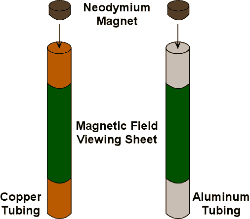
                    sometimes the correct answer is very easy ... without complication, the magnetic resonance in DS device is a kind of resonance beyond Lenz's law ... the following drawing show a known experiment :


                    if we use normal parallel resonating L/C circuit we are still inside the above experiment DS show this in one of his video after that he spun the magnet and it took a long time to fall down ...

                    we need to open the loop to achieve magnetic resonance ...

                    Comment


                    • Originally posted by AetherScientist View Post
                      I don't fully understand some questions about that device
                      1. Why not using the ends of the receivers? if you look at the receivers, there are wires connected NOT in the ends of the coil. Why?
                      2. What is the component that appears in all the receivers? a variable... capacitor?
                      3. What is the other component that also appears in all the receivers? it's a small black encapsulated component


                      this device is a simple experiment show us where to look for ? you have 3 coil around the main resonating system, each coil replicate the power from the center coil, now the question if the secondary coil from the main system replicate the same power from L1 ? finally L1 is the target ...!

                      Comment


                      • Originally posted by ilandtan View Post
                        I think so too. I'm not sure many people know how to create an efficient Tesla transmitter/receiver pair, including me. Much less a magnetically resonant one under DS design.

                        I was waiting for one of you gents to reverse engineer it
                        I was asking the other day about what magnetic resonance means. Some people told me that magnetic resonance is the same as inductive resonance.

                        Comment


                        • Originally posted by AetherScientist View Post
                          I was asking the other day about what magnetic resonance means. Some people told me that magnetic resonance is the same as inductive resonance.

                          the resonance in an open loop will depend on electron spin and this is the case of the E-TBC.

                          Comment


                          • This is where I need help. If it was a simple matter of finding inductive resonance why have so many people failed at replicating both DS and Tesla accomplishments? Don Smith said that he knew of only 6 out of hundreds who tried and succeeded replicating his experiment. (he didn't know why). I'm thinking that magnetic resonance happens at a slightly different frequency and our tuning is off. If Tesla said that this scaler pulses through the earth were faster then the speed of light, then we are looking at a wave characteristic that throws off our calculation of wavelength, because one of the variables is C. If we are not calculating wavelength correctly, our coils we are building for 1/4 lambda are borked. At the same time, we just aren't looking at our Gauss meters to find magnetically a increase in magnetism, we look for current increase, they may have a phase relationship. So we end up chasing the "wrong rabbit" because it's what our scopes show, and what we know how to calculate is inductive resonance. I have read somewhere that Tesla coil design has always been difficult because making efficient ones never follow the math, is that true? That the only accurate alignment to a smith chart could be achieved through TCTUTER program.

                            So I understand that dropping a magnet through a tube causes eddy currents that slow down the fall. But what does that have to do with magnetic resonance Med? Please enlighten me, I'm not putting it together.
                            Last edited by ilandtan; 01-05-2016, 01:07 PM. Reason: bold inductive resonance

                            Comment


                            • Originally posted by ilandtan View Post
                              This is where I need help. If it was a simple matter of finding inductive resonance why have so many people failed at replicating both DS and Tesla accomplishments? Don Smith said that he knew of only 6 out of hundreds who tried and succeeded replicating his experiment. (he didn't know why). I'm thinking that magnetic resonance happens at a slightly different frequency and our tuning is off. If Tesla said that this scaler pulses through the earth were faster then the speed of light, then we are looking at a wave characteristic that throws off our calculation of wavelength, because one of the variables is C. If we are not calculating wavelength correctly, our coils we are building for 1/4 lambda are borked. At the same time, we just aren't looking at our Gauss meters to find magnetically a increase in magnetism, we look for current increase, they may have a phase relationship. So we end up chasing the "wrong rabbit" because it's what our scopes show, and what we know how to calculate is inductive resonance. I have read somewhere that Tesla coil design has always been difficult because making efficient ones never follow the math, is that true? That the only accurate alignment to a smith chart could be achieved through TCTUTER program.

                              So I understand that dropping a magnet through a tube causes eddy currents that slow down the fall. But what does that have to do with magnetic resonance Med? Please enlighten me, I'm not putting it together.


                              Hi ilandtan !


                              sometimes we have to depend on our minds, i think it's the only chance for us ! if you understand the working principle behind the E-TBC magnetic resonance will be toward your eyes, the E-TBC is only a coil in the first sight it has an internal capacitor between CD junction :


                              the secret of this device is only the junction CD ... it's only one point! i call it the one dimensional capacitor because there where the real capacitor exist, Don Smith advised us to use the natural frequency forming a coil like the E-TBC ensure you have natural frequency, now if you are able to make this device oscillate using A VERY quick DC pulses preferably in KHZ if the E-TBC oscillate in MHZ ( so you have an interval time to let this device oscillate alone ... )

                              the DC pulses will provide a high voltage between the point A -- B ( this is why DS talk about kicking the voltage for L1 coil ..) if you have another capacitor behind the E-TBC to provide a high impedance for the HV signal you are using, when an electric current flow from A TO B a magmatic field will be generated, now where is the electric field ? as we know it inside ordinary capacitor where you have a separated plates ** remember in the E-TBC these plates are already connected together through the junction CD , i made an error in my published document about this junction finally i understood it must be closed ... ****

                              the induced rotating electric filed provide a constant difference of voltage across the E-TBC from A TO B if B=0 V B=2V the problem with these charges is that it can't be released until the magnetic field take a MAX VALUE and start collapsing just before it collapse the electric field will be visible as scalar potential at the same moment the magnetic field will take its max value, this is the moment when we have useful energy, it's also the time when Ozone gas will be released.. about the electrons they just change the spin rotation because the CW plate in front of your eyes will be CCW from behind ... this is why this geometry is very important, as you see the big player in this device is only the magnetic field even if we talk about the electric field it's generated from the magnetic field itself not from the induced current as normal parallel L/C ...

                              this device is beyond Lenz's law because there's no closed loop here ! from A TO B it's still en open coil ...

                              Comment


                              • Originally posted by ilandtan View Post
                                This is where I need help. If it was a simple matter of finding inductive resonance why have so many people failed at replicating both DS and Tesla accomplishments? Don Smith said that he knew of only 6 out of hundreds who tried and succeeded replicating his experiment. (he didn't know why). I'm thinking that magnetic resonance happens at a slightly different frequency and our tuning is off. If Tesla said that this scaler pulses through the earth were faster then the speed of light, then we are looking at a wave characteristic that throws off our calculation of wavelength, because one of the variables is C. If we are not calculating wavelength correctly, our coils we are building for 1/4 lambda are borked. At the same time, we just aren't looking at our Gauss meters to find magnetically a increase in magnetism, we look for current increase, they may have a phase relationship. So we end up chasing the "wrong rabbit" because it's what our scopes show, and what we know how to calculate is inductive resonance. I have read somewhere that Tesla coil design has always been difficult because making efficient ones never follow the math, is that true? That the only accurate alignment to a smith chart could be achieved through TCTUTER program.

                                So I understand that dropping a magnet through a tube causes eddy currents that slow down the fall. But what does that have to do with magnetic resonance Med? Please enlighten me, I'm not putting it together.
                                I will be here for a short period of time because I have to finish some work in 1 or 2 days and it will take me too much time, so I won't be able to post anything for weeks.

                                I recommend you to start investigating conventional RLC circuits and build the most simple device (resonant circuits of science first website). That is the most simple one. I recommend you to buy the next:
                                • High voltage module or a neon sign power supply (not the big transformer, the one I'm refering to is small one)
                                • Inductance meter to check that L1 and L2 have the same inductance.
                                • Variable capacitors to fine tuning the LC tank


                                You need to build 2 exactly LC circuits (receiver and transmitter must be the same). Then you need to feed the L1 with high voltage AC or pulsed DC and connect the load in the L2. Check youtube and websites about LC tank circuits, inductive coupling, etc...

                                Comment

                                Working...
                                X