To take full advantage of this effect, we must know and understand how flux density, permeability and the non linearity of cores work.
This was mastered a long time ago, and the devices which took advantage were known as Satruable Reactors, and Magnetic amplifiers.
Below is a graph of the B-H curve of a permeable core.
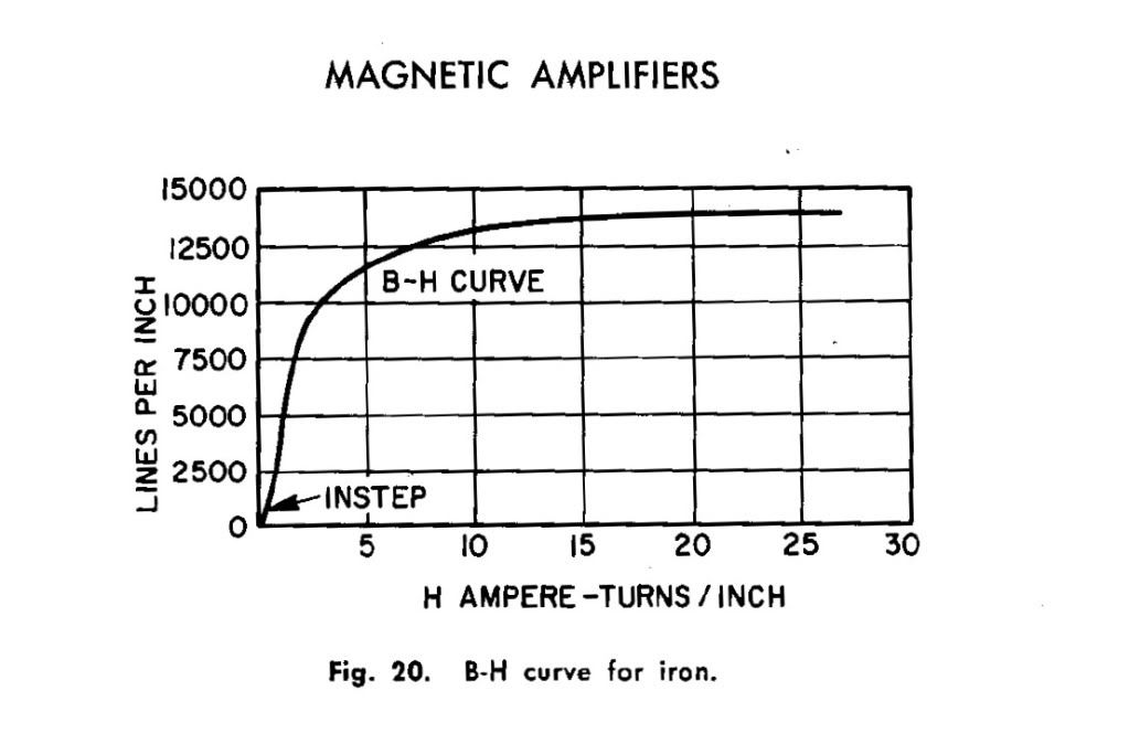
We can see as the ampere turns per inch increases, the lines of flux per inch changes in a NON LINEAR way.
Thus there is a portion of the curve (the more vertical section of the curve) which allows a small change in the ampere turns per inch causes a large change in lines per inch. Said another way, a small change in the magnetic field applied to the core, causes a LARGE change in the permeability of the core (and hence a large change in the inductance of a coil associated with the core).
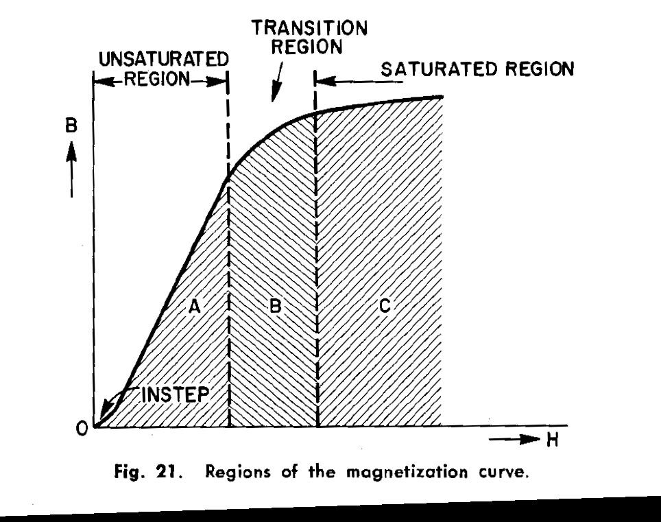
Thus we want to BIAS our core in the unsaturated region (A) so that a small change in the input causes a large change in permeability. See section A of graph below:
This amplification effect can be seen in the graph below, where an input is shown to affect an output.
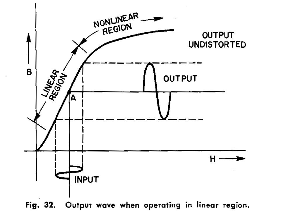
In the case above, a control winding is used to alter the permeability of the core. An inductor with an AC current through it sees a change in the impedance of its winding. Thus a small change in input current causes a large change in current through the secondary winding, this is how a mag amp works!
Lets take a look at the Alexanderson # 1,328,797 figure 1.
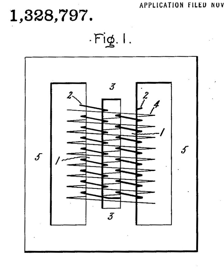
Notice the two windings, and two flux paths.
If the internal winding (labled in figure as: #2) is wound in such a was as to have NO mutual inductance with the other winding (#4) then there will be no transformer action. This can be accomplished with two mirror windings. Winding 2 will create a flux circuit which circles the two smaller legs around which it is wound. The winding 4 will see flux paths in two opposite directions within its center, and so will have NO EMF induced.
Therefore, winding 2 can create a change in inductance for the core, without affecting winding 4. This can operate the other way around also. The important thing to take note of: The two windings have NO mutual inductance. They do not operate as a transformer. One changes the impedance of the core only.
The issue is this....
If you have a control winding used to change the inductance of a secondary winding, no EMF will be induced on the secondary with only a change in inductance to cause it.
But, if the secondary sees a change in a coherent magnetic field, then an EMF will be induced.
Therefore magnets will serve two purposes when added to a magnetic amplifier.
1) The magnets will bias the core, bringing it into the region where a small change in input creates a large change in permeability.
2) The magnets will create a coherent magnetic field within the core. As the permeability changes, the flux density within the core changes as well. This creates a change in B field with respect to time for the inductor winding to see! Now instead of doing nothing as the permeability is changed, an EMF is induced.
I hope I have explained this well, and the ramifications are understood.
This was mastered a long time ago, and the devices which took advantage were known as Satruable Reactors, and Magnetic amplifiers.
Below is a graph of the B-H curve of a permeable core.

We can see as the ampere turns per inch increases, the lines of flux per inch changes in a NON LINEAR way.
Thus there is a portion of the curve (the more vertical section of the curve) which allows a small change in the ampere turns per inch causes a large change in lines per inch. Said another way, a small change in the magnetic field applied to the core, causes a LARGE change in the permeability of the core (and hence a large change in the inductance of a coil associated with the core).
Thus we want to BIAS our core in the unsaturated region (A) so that a small change in the input causes a large change in permeability. See section A of graph below:

This amplification effect can be seen in the graph below, where an input is shown to affect an output.

In the case above, a control winding is used to alter the permeability of the core. An inductor with an AC current through it sees a change in the impedance of its winding. Thus a small change in input current causes a large change in current through the secondary winding, this is how a mag amp works!
Lets take a look at the Alexanderson # 1,328,797 figure 1.

Notice the two windings, and two flux paths.
If the internal winding (labled in figure as: #2) is wound in such a was as to have NO mutual inductance with the other winding (#4) then there will be no transformer action. This can be accomplished with two mirror windings. Winding 2 will create a flux circuit which circles the two smaller legs around which it is wound. The winding 4 will see flux paths in two opposite directions within its center, and so will have NO EMF induced.
Therefore, winding 2 can create a change in inductance for the core, without affecting winding 4. This can operate the other way around also. The important thing to take note of: The two windings have NO mutual inductance. They do not operate as a transformer. One changes the impedance of the core only.
The issue is this....
If you have a control winding used to change the inductance of a secondary winding, no EMF will be induced on the secondary with only a change in inductance to cause it.
But, if the secondary sees a change in a coherent magnetic field, then an EMF will be induced.
Therefore magnets will serve two purposes when added to a magnetic amplifier.
1) The magnets will bias the core, bringing it into the region where a small change in input creates a large change in permeability.
2) The magnets will create a coherent magnetic field within the core. As the permeability changes, the flux density within the core changes as well. This creates a change in B field with respect to time for the inductor winding to see! Now instead of doing nothing as the permeability is changed, an EMF is induced.
I hope I have explained this well, and the ramifications are understood.

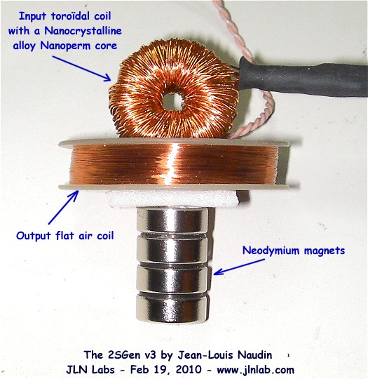


 I think this is a GREAT benefit to the system since that means reduced EM output and reduces the chance of interference with the system's operation and of close by equipment.
Comment