Announcement

Collapse
No announcement yet.

Charge conserving Capacitive Spring.

Collapse
X
 
  • Filter
  • Time
  • Show
Clear All
new posts

  • Originally posted by Armagdn03 View Post
    the best possible connection to load is an impedance matched transformer to your load. This allows for an almost impedance free movement of coulombs through the load, which is optimal.

    You are definitely correct that there is a trade off between cap size ratio, to voltage and coulombs moved. To get higher voltage differential, you sacrifice coulombs moved and vice versa.

    There are lots of cool applications and im just exploring some of the ideas, helps to understand the situation from several angles.
    Can you explain in detail ? do you mean resonant circuit with transformer secondary and capacitor ? Isn't that only for pure resistive loads ?
    what about inductive loads ?

    Comment


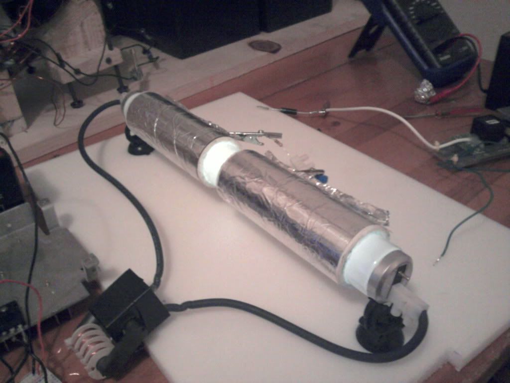
    • I decided to properly insulate the solid state switching tube shown by Armagdn03. I used PVC and silicon to fill in the gaps. It definitely holds a charge long enough to run some initial tests.


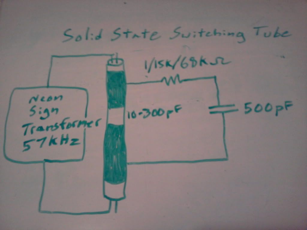
      Here is the simplified circuit being used:


      These capacitors are being charged with a voltage source equaling 7.5KV.

      I am sure that the tube that I have constructed can vary pretty highly in capacitance, but I am only going to list the values that I have seen while the tube is being excited at approximately 57kHz. The variation in capacitance is 10pF - 300pF.

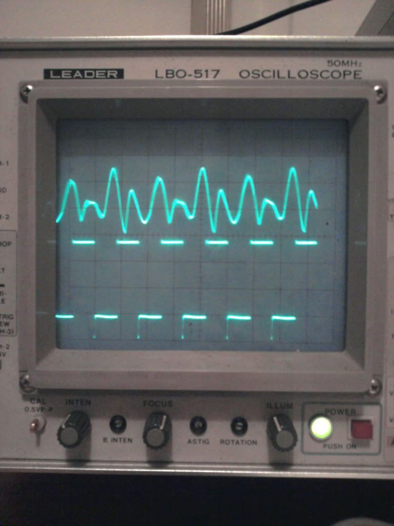
      I have charged the capacitors up with the 7.5KV source of voltage and attached my oscilloscope to the load (resistor between the two capacitors). I have seen some variation in voltage across the load, but it seems to be more of an electrostatic interference from the tube than an actual reading since the waveform looks the same when the capacitors are charged or discharged.

      Charged/Discharged (No Difference in waveforms) Capacitor Waveform(1V/Division-Ch1&2, 10uS/Division):
      Top Trace: Load Resistor
      Bottom Trace: Square Wave Oscillator


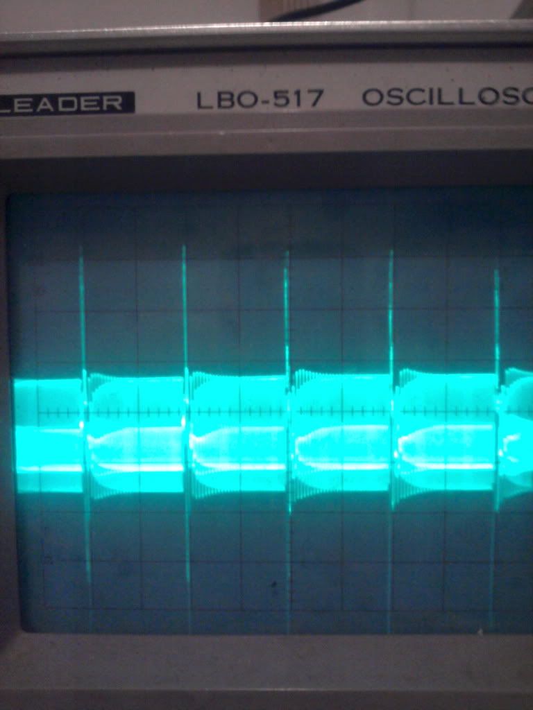
      There is a beat frequency of 1kHz of which I don't know the origin. Waveform(1V/Division-Load(Fluorescent tube output interferance - Probe placed across load resistance):


      I have felt no noticeable heat from any of the resistances that I have used despite i^2R saying that there should be lots of heat.

      I understand that since we are moving a finite quantity of charge that we must choose our resistors accordingly. If physical variance of capacity is too slow, we must choose a resistor that meets the practical RC time constant. Like SilverToGold said, the 1 ohm resistor is for a time constant that is currently out of my reach.

      In my case, I can only get my arduino prototyping board to cycle at 57kHz. This puts my RC time constant resistance for my Cstatic = 500pF at about 68Kohms and my 5t time constant at about 15Kohm.

      I know there is a resistance that will be most efficient for the capacities being used. However, I have not seen any sign of power distribution through the load.

      The resistor in question has remained cold to the touch while cycling capacitance phases at 57KHz(with a theoretical charge to time ratio of about 250mA).

      At a time constant of that magnitude, I should have a burnt up 15K(1/4watt) resistor since the total R*Q/t equals about (15Kohm*(57KHz*2*(2.2E-6))) = 3762 average voltage.

      Average Current * Average Voltage = Average Power

      250mA * 3762V = 940 watts = Theoretically a burnt up 15Kohm-1/4 watt resistor...

      Got any ideas on where I am falling short?


      Dave

      Comment


      • Hello, thanks for doing some of the leg work!

        I have found similar difficulties. Mainly the thing I dont like is the lack of control in turning the tube on and off. The high voltage makes everything really difficult.

        For this reason, I am currently focusing on the Cross Field Capacitor, (which is also high voltage, will have to think on this)

        And also plan on starting a thread into my experimentation with Alexanderson Mag Amp setups. The mag amps are much simpler to play with and considerably less dangerous. The high voltage experiments are quite lethal.

        Comment


        • Fast, adjustable arduino impulser.

          Here is an Arduino program I wrote. It has a fixed, small duty cycle, uses a potentiometer to adjust the frequency, and uses direct register manipulation and assembly as often as possible to increase the possible frequency.

          I'd be interested in seeing what kind of frequency you can get out of it.

          // defines for setting and clearing register bits
          #ifndef cbi
          #define cbi(sfr, bit) (_SFR_BYTE(sfr) &= ~_BV(bit))
          #endif
          #ifndef sbi
          #define sbi(sfr, bit) (_SFR_BYTE(sfr) |= _BV(bit))
          #endif

          int sensorValue = 0;

          void setup() {
          // initialize the digital pin as an output.
          pinMode(3, OUTPUT);
          pinMode(A5, INPUT);
          // set prescale to 16
          sbi(ADCSRA,ADPS2) ;
          cbi(ADCSRA,ADPS1) ;
          cbi(ADCSRA,ADPS0) ;
          }

          void loop() {
          // Read pin 5 to determine the frequency.
          // Potentiometer middle terminal connected to pin 5
          // Outside terminals connected to +5V and gnd
          sensorValue = analogRead(A5);
          while (sensorValue--) {
          __asm__("nop\n\t");
          }

          PORTD |= B1100; // Set port 3 to high
          // Add or remove nop operations to change the pulse width
          __asm__("nop\n\t""nop\n\t""nop\n\t""nop\n\t""nop\n \t""nop\n\t""nop\n\t""nop\n\t");
          __asm__("nop\n\t""nop\n\t""nop\n\t""nop\n\t""nop\n \t""nop\n\t""nop\n\t""nop\n\t");
          __asm__("nop\n\t""nop\n\t""nop\n\t""nop\n\t""nop\n \t""nop\n\t""nop\n\t""nop\n\t");
          __asm__("nop\n\t""nop\n\t""nop\n\t""nop\n\t""nop\n \t""nop\n\t""nop\n\t""nop\n\t");
          PORTD = B0000; // Set port 3 to low
          }

          Comment


          • Originally posted by 7imix View Post
            Here is an Arduino program I wrote. It has a fixed, small duty cycle, uses a potentiometer to adjust the frequency, and uses direct register manipulation and assembly as often as possible to increase the possible frequency.

            I'd be interested in seeing what kind of frequency you can get out of it.
            I am really not very experienced in micro-controllers, I would be interested to see what YOU can do!!!

            Comment


            • Great work Web000x and a nice attempt.

              The problem with holding charges is not just to insulate it from the florescent tube but to also stop the ions flowing off of any sharp points in your varying capacitor, load and even your static cap.

              Unfortunately, these systems can not be ran just by piecing it together. Careful planning must be done.

              Looking at your setup, there is a problem with the Al foil hanging loose where you attach your leads, the alligator clips are not good for such high voltage work (too many sharp points). The entire setup pretty much must be entirely encased to prevent voltage leakage.

              With your setup, the voltage probably leaks off within a few seconds to the point that it's a small fraction of it's initial value.

              When you have sharp edges and high voltages (7.5 kV is quite high), the edges will leak voltage and you will smell "ozone" in the air.

              Remember that these caps are very small and hold very small charges. A little loss charge and your system pretty much poops out.

              I also believe that load placement is very important and so is grounding one leg of the system. I would totally insulate one half of the cap circuit loop to keep all charges. I would then place the load and a ground connection to the other half. This would allow charges to be lost in that half but replaced by the ground connection.

              This system requires careful thought to get it working properly.

              Comment


              • Originally posted by Web000x View Post
                The resistor in question has remained cold to the touch while cycling capacitance phases at 57KHz(with a theoretical charge to time ratio of about 250mA).

                At a time constant of that magnitude, I should have a burnt up 15K(1/4watt) resistor since the total R*Q/t equals about (15Kohm*(57KHz*2*(2.2E-6))) = 3762 average voltage.

                Average Current * Average Voltage = Average Power

                250mA * 3762V = 940 watts = Theoretically a burnt up 15Kohm-1/4 watt resistor...

                Got any ideas on where I am falling short?


                Dave
                These systems deliver lumps of power each cycle so you can't use the simple equation with this system.

                One lump of energy is transfered when the cap gets larger and another larger one when the cap gets smaller. The system is not symmetrical in it's energy transfer. Two different lumps per each cycle of the tube.

                The equation I posted earlier is also not correct, it was based on improper understanding of this circuit. I have a more accurate equation based on better understanding but it's quite complicated so I refrained from posting it.

                If your systems parameters were really:

                Vi = 7500 V
                Cmax = 300 pF
                Cmin = 10 pf
                Co = 500 pF
                f = 57 kHz

                Your ideal output would be 5652 Watts.

                I can tell that you're not keeping the charge because your waveform across your load is not what would be expected. There should be large spikes one way and then another the other way each time the capacitance changes. You would also need a special super high voltage probe to measure them.

                Also since the waveform does not change regardless of caps being charged or not means that it's just being induced from the tube's power source.

                Also, the waveform you are seeing may also be just from your scope acting like an antenna. When you've got high voltage and high frequencies, you get your probe too close and it'll act like an antenna picking up the tube's power input.

                If your system was really working, your tube would glow brighter than if the cap system was not attached to it. Power is being delivered to the tube each time the tube turns off and will reignite the tube. This means more light.
                Last edited by SilverToGold; 07-06-2011, 12:13 AM.

                Comment


                • One other suggestion to deal with the voltage leakage system.

                  You don't have to use a static cap for testing purposes. You could connect up a high voltage power source connected to as large a cap as you can find to replace the static cap.

                  When these systems operate and you have a large static cap, the voltage on these caps do not change much. The large changes really occur on the variable cap side.

                  The voltage there will swing in proportion to the cap ratio. With your system measurements (if they were achieved in operation),

                  Your highest voltage spike across the variable cap is about (Cmax/Cmin*Vinitial). That's about 300/10*7500 = 225 kV!

                  Does this give you any idea why you are losing your charges so quickly? Your system is not designed to operate with these voltages.

                  A cycle or two and your charges are mostly gone. So that is why you are getting the same scope readings regardless if the caps are charged or not. In the end, the system quickly goes to the same state. Hardly any charges on your caps and just antenna action from your probe.
                  Last edited by SilverToGold; 07-05-2011, 11:55 PM.

                  Comment


                  • @SilverToGold,

                    I am not sure we are seeing eye to eye on the what causes the energy output of this system. I will present my idea of how I am calculating the power output of this circuit.

                    First, we have a variation in capacity that is moving our charges between the two capacitors. Ideally without loss, charge will travel from Cstatic(Cs) to Cdynamic(Cd) and visa versa.


                    As you can see from the illustration, a finite quantity of charge is shuttled through the load impedance in each direction. This quantity of charge is dictated solely on the voltage and capacitance variation of Cd and is not related to Cs. Your energy output of the system is a function of charge(Q=CV)/t through the loading resistor.

                    The equation for Power in an electrical system is defined as P=I^2*R. In order to use this equation, we must first find our charge to time ratio, our amperage.

                    This is a direct quote from wikipedia defining the Ampere:
                    Conversely, a current of one ampere is one coulomb of charge going past a given point per second.
                    1 Ampere = Coulomb/Second

                    The total charge is found by taking Cmax value of 800pF and multiplying it by 7.5KV.

                    Qtot = 800pF*7.5KV = 6x10^-6 Coulombs

                    Now we will find the charge difference between the capacitors:
                    (6x10^-6)/510pF = 11.76KV

                    Initial charge of variable cap minus the charge after variation:
                    (300pF*7.5KV) - (10pF*11.76KV) = 2.13x10^-6 Coulombs

                    This last quantity,2.13x10^-6 Coulombs, is the amount of charge that is shuttled through the resistance on each capacitance variation.

                    Since we know that my frequency was running at 57KHz, we can find out how many times per second a quantity of charge is moving through the resistor. Our charge being moved is going to be doubled. Since each time the tube lights, the capacitance goes from Cmax to Cmin and from Cmin to Cmax again.

                    Finding the average amperage (total coulombs moved in 1 Sec) through the resistor:
                    (Frequency*2*Charge being Shuttled = Amperage)
                    57000*2*(2.13x10^-6) = 243mA

                    Finding the power dissipation in the resistor:
                    (I^2*R = Watts)
                    243mA^2*15KOhm = 885.7 Watts

                    Let me know where we are not seeing straight so that we can sort this out.

                    With your setup, the voltage probably leaks off within a few seconds to the point that it's a small fraction of it's initial value.
                    Yes, the voltage does leak off, but it is not so fast that I wouldn't be able to produce some noticeable heat off of the load resistor if there was charge flowing through it.

                    I still get a small shock after a few minutes of charge settling. This shock has to be in the 500V range according to my fingers. At 500V using the calculations that I used above, I should still have 4 Watts of power dissipation in the resistor. Being a 1/4 Watt resistor, I would feel that heat, but have felt absolutely nothing.
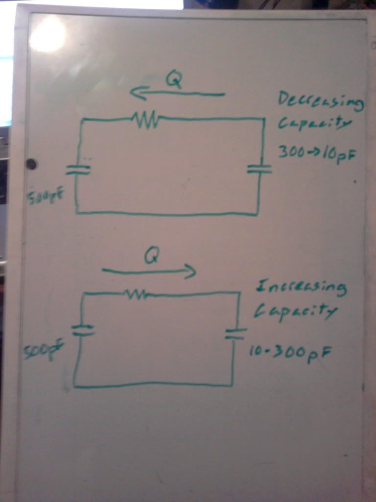
                    The charge stays in the capacitor long enough to test to see if this way is promising, and unfortunately I am becoming discouraged in this particular setup.

                    I am beginning to believe that this tube's molecular orientation of plasma (Capacitance variation) is fighting too hard with the dielectric lines of force and is keeping anything unusual from happening. I will continue to poke and prod, but I may start looking into a mechanical setup.

                    What do you think about and epoxy resin casting filled with Titanium Dioxide particles as static dielectric? This would work like Chris Carson's device with metal plates rotating right outside of the dielectric material and the dielectric being slotted. The capacitance variation should be much higher, theoretically.


                    Dave

                    Comment


                    • That was how I initially thought the power could be calculated but it's not correct. That equation for power is the instantaneous power and works fine for DC or some averaged current. We do not have that value.

                      In other words, you know how much Q is shuffled but you do not know under what pressure (ie voltage) that is happening. Power = I*V = (dQ/dt)*V. That voltage changes with time, so the instantaneous power changes with time. You can not just calculate it as you have done.

                      Power is the sum of that energy over time. So the proper way to look at this is to look at the ENERGY in the system and how it changes with each change in capacitance over time and sum them up (just multiplying Energy per cycle by the frequency).

                      Looking at just the Q will not give you the correct answer since we do now know enough about it to do simple calculations. We could do it that way but it would require some calculus (integrating up the instantaneous power over time).

                      Energy is not "conserved" in the circuit loop but the charge is. That gives us the proper energy for this system at any time.

                      A) When the light goes on, the capacitance of the system goes up, the energy of the system goes down and so does the voltage. We assume most of that energy difference goes into the load.

                      B) When the light goes off, the capacitance of the system goes down, the energy of the system goes up (with the voltage). We assume most of that energy difference goes into the load.

                      This is the basic two steps required to properly calculate the energy (and consequent power) in each cycle. We can then multiply that times the frequency to get the total power.

                      When you finish this, you will find that the energy is the square of the voltage and a large function of the variable capacitance ratio. So if you understand anything about exponential growth, you will understand how a little change can go from minute power to enormous power.

                      I agree that there are some things to consider with the turning on and off of these tubes. If we just assume that the tube is actually turning on and off but not really measuring the light intensity or the current in the tube's power supply, we do NOT know what really is going on and just assuming things that are CRITICAL for the tube to function. Not good analysis to get this thing working.

                      So if the tube is not properly turning on/off, you are not going to pump many charges.

                      These tubes are usually ran at 20-30 kHz. Maybe you are running it too fast to properly turn on/off. Faster is better but maybe not workable with these tubes.

                      In short, if you are running at 500V and not getting true on/off turning of the tube so you cap ratio is not 30 but more like 3, you are getting probably microwatts through that load.

                      Originally posted by Web000x View Post
                      @SilverToGold,

                      I am not sure we are seeing eye to eye on the what causes the energy output of this system. I will present my idea of how I am calculating the power output of this circuit.

                      First, we have a variation in capacity that is moving our charges between the two capacitors. Ideally without loss, charge will travel from Cstatic(Cs) to Cdynamic(Cd) and visa versa.


                      As you can see from the illustration, a finite quantity of charge is shuttled through the load impedance in each direction. This quantity of charge is dictated solely on the voltage and capacitance variation of Cd and is not related to Cs. Your energy output of the system is a function of charge(Q=CV)/t through the loading resistor.

                      The equation for Power in an electrical system is defined as P=I^2*R. In order to use this equation, we must first find our charge to time ratio, our amperage.

                      This is a direct quote from wikipedia defining the Ampere:

                      1 Ampere = Coulomb/Second

                      The total charge is found by taking Cmax value of 800pF and multiplying it by 7.5KV.

                      Qtot = 800pF*7.5KV = 6x10^-6 Coulombs

                      Now we will find the charge difference between the capacitors:
                      (6x10^-6)/510pF = 11.76KV

                      Initial charge of variable cap minus the charge after variation:
                      (300pF*7.5KV) - (10pF*11.76KV) = 2.13x10^-6 Coulombs

                      This last quantity,2.13x10^-6 Coulombs, is the amount of charge that is shuttled through the resistance on each capacitance variation.

                      Since we know that my frequency was running at 57KHz, we can find out how many times per second a quantity of charge is moving through the resistor. Our charge being moved is going to be doubled. Since each time the tube lights, the capacitance goes from Cmax to Cmin and from Cmin to Cmax again.

                      Finding the average amperage (total coulombs moved in 1 Sec) through the resistor:
                      (Frequency*2*Charge being Shuttled = Amperage)
                      57000*2*(2.13x10^-6) = 243mA

                      Finding the power dissipation in the resistor:
                      (I^2*R = Watts)
                      243mA^2*15KOhm = 885.7 Watts

                      Let me know where we are not seeing straight so that we can sort this out.

                      Yes, the voltage does leak off, but it is not so fast that I wouldn't be able to produce some noticeable heat off of the load resistor if there was charge flowing through it.

                      I still get a small shock after a few minutes of charge settling. This shock has to be in the 500V range according to my fingers. At 500V using the calculations that I used above, I should still have 4 Watts of power dissipation in the resistor. Being a 1/4 Watt resistor, I would feel that heat, but have felt absolutely nothing.
                      Last edited by SilverToGold; 07-06-2011, 03:05 PM.

                      Comment


                      • Without measurements, we are only assuming the charges stay long enough and that the system is doing what it should. We just don't know except that it's not working as you expect it to.

                        From my own experience, the system does pump charges for certain so that's why I believe it works. We also have Joseph Hiddink patent and stories that back up that this system does pump charges.

                        Also from the word of Chris Carson, Eric Dollard and the numerous government patents related to capacitive parametric variations - we know these systems "synthesize energy".

                        All the mechanical setups in the patents were ran under vacuum. If I were going to do a mechanical system, I would use those dielectrics to totally encase one set of plates and I would probably vibrate them as oppose to rotate them.

                        The mechanical systems are just no match for the electrical ones.

                        Originally posted by Web000x View Post
                        The charge stays in the capacitor long enough to test to see if this way is promising, and unfortunately I am becoming discouraged in this particular setup.

                        I am beginning to believe that this tube's molecular orientation of plasma (Capacitance variation) is fighting too hard with the dielectric lines of force and is keeping anything unusual from happening. I will continue to poke and prod, but I may start looking into a mechanical setup.

                        What do you think about and epoxy resin casting filled with Titanium Dioxide particles as static dielectric? This would work like Chris Carson's device with metal plates rotating right outside of the dielectric material and the dielectric being slotted. The capacitance variation should be much higher, theoretically.


                        Dave

                        Comment


                        • Wow, very interesting conversation I missed here.

                          I definitely agree on the whole need for a more "well built" experiment. It was a good first go at it, but you are seeing the problems with HV!!!

                          First and foremost, we need to know that two important things are happening (which have allready been talked about).

                          1) The tube needs to turn nicely on and off each cycle. I have been working on this problem also, this is why some people have used different tubes (UV) for their different phosphor coatings, lack of phosphor, quench times of gasses used etc. I dont think a simple spark gap system is going to work too well. We need a nicely designed power supply which can oscillate the tubes around their ionization point.

                          2) The charge on the system must stay constant! With voltage that can be developed leakage can be a big problem. If you do not have a power supply to top off the cap constantly to compensate for leakage, you are dead in the water very quickly.

                          Comment


                          • Originally posted by SilverToGold View Post
                            That was how I initially thought the power could be calculated but it's not correct. That equation for power is the instantaneous power and works fine for DC or some averaged current. We do not have that value.

                            In other words, you know how much Q is shuffled but you do not know under what pressure (ie voltage) that is happening. Power = I*V = (dQ/dt)*V. That voltage changes with time, so the instantaneous power changes with time. You can not just calculate it as you have done.
                            I'm going to have to continue to defend my position about the idea that we do have some averaged current to work with. Let me explain..

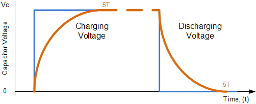
                            First let us look at the capacitance being used to find the maximum charge transfer time that will take place. The equation for finding this is 5(RC) = Time period that it takes to move 99.3% of charge into or out of a capacitor.

                            The equations showing showing the waveforms of charging/discharging capacitors are here:

                            Capacitor Charging Equation = V(1-e^(-t/RC))
                            Capacitor Discharging Waveform = V(e^(-t/RC))
                            where
                            t = Time
                            C=capacitance


                            Look at the Capacitor Discharging Waveform. The area under the curve is representative of the amount of charge being shuttled upon each half cycle. We already know the area under the curve. That area of is based on the amount of charge that is shuttled for each capacitance variation. This total area encompassed by 1 second is effective amperage.

                            Although the voltage/amperage levels are always fluctuating as seen by the illustration, we do not need to know instantaneous values since we can figure out everything from the quantity of charge being shuttled/unit of time. This does work without the need for calculus.

                            If we have our charge moving through a resistance for a quantity of time, we can figure out our power. Power is not only represented by P=V*I but also by P=I^2*R = (dQ/dt)^2*R. We can use this equation without voltage.

                            For all practical purposes, we really don't need to know instantaneous Power values for initial tests. I am only concerned with Average Power

                            Average Power can be calculated with only:
                            1. Charge/unit of time
                            2. Resistance that charge is flowing through

                            I promise that I'm not trying to intentionally argue with you, but I have yet to see any convincing evidence that this is not the way that you would calculate the power produced by the system. Any thoughts are welcome.

                            I agree that there are some things to consider with the turning on and off of these tubes. If we just assume that the tube is actually turning on and off but not really measuring the light intensity or the current in the tube's power supply, we do NOT know what really is going on and just assuming things that are CRITICAL for the tube to function. Not good analysis to get this thing working.

                            I think this may be where my issue might be. I am using a 12 Volt supply to pulse the primary of this neon sign transformer. I think the tube excitation is primarily being triggered off of the collapse of the magnetic field of the primary. I am probably triggering the tube with only the transient spike and possibly a weee bit of forward EMF from the XFMR. That would severely throw off my time constants.

                            Thanks for your help.


                            Dave

                            Comment


                            • Originally posted by Armagdn03 View Post
                              Wow, very interesting conversation I missed here.

                              I definitely agree on the whole need for a more "well built" experiment. It was a good first go at it, but you are seeing the problems with HV!!!

                              First and foremost, we need to know that two important things are happening (which have allready been talked about).

                              1) The tube needs to turn nicely on and off each cycle. I have been working on this problem also, this is why some people have used different tubes (UV) for their different phosphor coatings, lack of phosphor, quench times of gasses used etc. I dont think a simple spark gap system is going to work too well. We need a nicely designed power supply which can oscillate the tubes around their ionization point.

                              2) The charge on the system must stay constant! With voltage that can be developed leakage can be a big problem. If you do not have a power supply to top off the cap constantly to compensate for leakage, you are dead in the water very quickly.
                              Yeah, I know these things need to be engineered correctly, but I have very limited time these days. I usually don't build "all out" until I see that there is something to be had. I'm sure I have missed some real gems that way, but I'm not funded nor have the man power to do everything right. Wouldn't it be nice to quit your day job and build/experiment on somebody else's dime...

                              I really appreciate all of the insight that you have given. You are a clear thinker amongst all of the chaos.

                              Dave

                              Comment


                              • Sure you can work it out with the basic technique you've described (more than one way to skin a cat when it comes to math), I am not saying you can't. But you're missing some important points as to why it's not as simple as you've calculated.

                                Average Power means you need to know the average current and that means you need to know the time constant also since you are only working from Q.

                                Let me ask you some fundamental questions since you are using what you believe to be the average power.

                                So what is your average current (dQ/dt) that you are going to use?

                                What is your average current when the cap increases?
                                What is your average current when the cap decreases?


                                You are aware that these are not the same values? The voltage changes are different. The average I is different also. Even though the Q is the same!

                                You also can't get the average current unless you know the voltage it's changing from and to where it's going to. So I ask you:

                                What voltage is it changing from when the cap increases? Also what voltage is it changing TO when the cap increases?
                                What voltage is it changing from when the cap decreases? Also what voltage is it changing TO when the cap decreases?


                                You have to know the above answer to both caps!

                                Do you now see why your technique as you've used it is not appropriate? You've simplified it too much that it's basically wrong.

                                Also, R is not just the R of the resistor, the R is the entire resistances in your loop. This includes the resistance through the tube. Without knowing exactly what R is, we don't even know the real time constant.

                                Another point in regards to time constant (ie RC).... what exactly is your C?? Is it the static C? Is it the variable C? If so, which one Cmax or Cmin? Or is it some combination there of? Easy to make a mistake here. This alone should show you why the system is not as simple as you've made it to be. The time constant is different when the cap is charging versus when it's discharging.

                                A small change in time constant and you get different energy results. You're off by 20% in the RC and you're off 20% in your results.

                                So unless you can really answer these question to yourself and really understand what is happening when these charges are shuttled back and forth, you can't really use the simple method you've suggested.

                                It could be done with more work as I've pointed out above but there is a simpler method that does not depend on average I or the time constant as long as it's a lot larger than 5RC and that's to just look at the energy before and after the system changes.

                                And regardless of which technique anyone use, there is one answer and whatever technique used should yield the same answer. Agreed?

                                I think looking at the energy and going through each step of the process will yield the easiest and most reliable answer. Which is what I've done.

                                Originally posted by Web000x View Post
                                First let us look at the capacitance being used to find the maximum charge transfer time that will take place. The equation for finding this is 5(RC) = Time period that it takes to move 99.3% of charge into or out of a capacitor.

                                The equations showing showing the waveforms of charging/discharging capacitors are here:

                                Capacitor Charging Equation = V(1-e^(-t/RC))
                                Capacitor Discharging Waveform = V(e^(-t/RC))
                                where
                                t = Time
                                C=capacitance


                                Look at the Capacitor Discharging Waveform. The area under the curve is representative of the amount of charge being shuttled upon each half cycle. We already know the area under the curve. That area of is based on the amount of charge that is shuttled for each capacitance variation. This total area encompassed by 1 second is effective amperage.

                                Although the voltage/amperage levels are always fluctuating as seen by the illustration, we do not need to know instantaneous values since we can figure out everything from the quantity of charge being shuttled/unit of time. This does work without the need for calculus.

                                If we have our charge moving through a resistance for a quantity of time, we can figure out our power. Power is not only represented by P=V*I but also by P=I^2*R = (dQ/dt)^2*R. We can use this equation without voltage.

                                For all practical purposes, we really don't need to know instantaneous Power values for initial tests. I am only concerned with Average Power

                                Average Power can be calculated with only:
                                1. Charge/unit of time
                                2. Resistance that charge is flowing through

                                I promise that I'm not trying to intentionally argue with you, but I have yet to see any convincing evidence that this is not the way that you would calculate the power produced by the system. Any thoughts are welcome.
                                Last edited by SilverToGold; 07-06-2011, 10:27 PM.

                                Comment

                                Working...
                                X