Announcement

Collapse
No announcement yet.

Charge conserving Capacitive Spring.

Collapse
X
 
  • Filter
  • Time
  • Show
Clear All
new posts

  • #31
    Ok, I want to calculate it anyway .

    We have:
    C1 (now in series) which is 0.0235F with a charge of 0.0235F @ 20V = 0.47J
    C2 which is 0.094F with a charge of 0.094F @ 10V = 0.94J

    To find the final voltage:

    Ctot.= 0.0235F + 0.094F = 0.1175F
    Qtot.= 0.47Q + 0.94Q = 1.41Q
    Vtot. = 1.41Q / 0.1175F = 12V

    So you were right, even if we were not talking about the same exact setup.
    This confirms the loss I am seeing by measurement.

    regards,
    Mario

    Comment


    • #32
      Originally posted by Mario View Post
      Ok, I want to calculate it anyway .

      We have:
      C1 (now in series) which is 0.0235F with a charge of 0.0235F @ 20V = 0.47J
      C2 which is 0.094F with a charge of 0.094F @ 10V = 0.94J

      To find the final voltage:

      Ctot.= 0.0235F + 0.094F = 0.1175F
      Qtot.= 0.47Q + 0.94Q = 1.41Q
      Vtot. = 1.41Q / 0.1175F = 12V

      So you were right, even if we were not talking about the same exact setup.
      This confirms the loss I am seeing by measurement.

      regards,
      Mario

      You are not seeing a loss in measurement, unless you are not completing the cycle.

      For example at this point:

      C1 = .094F @ 12V
      C2 = .0235F @ 12V

      If we switch C2 into parallel again, we have .094F @ 6V.


      C1 = .094F @ 12V
      C2 = .094F @ 6V.

      Which gives us a charge of
      C1= 0.094c * 12v = 1.128q
      C2 = 0.094c * 6v = 0.564q

      Qtot = 1.128 + 0.564 = 1.844

      And we have a capacitance total of .094 + .094 = 0.188

      Now knowing we that Vtot = Qtot/Ctot 1.844 / 0.188 = 9.85V across C1 and C2, and they started at 10v each.

      which is 98.5% of the original energy, and I would be willing to bet that the 1.5% missing is due to rounding error.

      So where is this loss?

      Comment


      • #33
        Hi Andrew,

        there's a mistake in your calculation:

        Qtot = 1.128 + 0.564 = is 1.692 not 1.844

        Capacitance total of .094 + .094 = 0.188

        So Vtot = Qtot/Ctot 1.1.692 / 0.188 = 9V across C1 and C2.

        So we started with C1+C2 (0.094F + 0.094F)= 0.188F @ 10V = 9.4 Joules
        After we switched C1 to series and back to parallel we end up with C1 + C2 = 0.188F @ 9V = 7.614 Joules
        This means in one complete cycle we've lost 19% of the initial energy. Btw 9V is what I actually measured when connecting back to parallel.

        If we summarize the individual steps:

        At start C1 is in parallel, total energy of C1+C2 0.188F @ 10V is 9.4 Joules.

        1) C1 gets switched to series (20V) and discharges into C2 (10V) resulting in 12V across C1-C2. Energy left is 0.5*((0.0235F + 0.094F)*12V^2) = 8.46 Joules. In one passage we have lost 10% of the initial energy.

        2) C1 gets switched back to parallel (6V) and receives discharge coming back from C2 (12V) resulting in 9V across C1-C2. Energy left is 0.5*((0.094F + 0.094F)*9V^2) = 7.614 Joules. In this step too we have lost 10% of energy with regards to the 8.46 Joules of the previous step. But in one complete cycle (back and forth) we have lost 19% of energy since we are left with 7.614 Joules with regards to 9.4 Joules we had at start.
        Does this sound right?

        regards,
        Mario

        Comment


        • #34
          Hi guys
          I am following this thread with interest. I think that charging caps and putting them in series and parallel is not the same as physically changing a capacitance of a single cap. There mist ne a difference. To test the concept out I would use a variable capacitor that is made so that it can rotate around full 360 degrees and put a small high speed motor on the shaft. Then I would put this small cap in parallel with a standard cap through a low impedance load (transformer primary). I guess to see the difference with a capacity that small, I would need to use several hundereds of volts.
          Thanks,
          Jetijs
          It's better to wear off by working than to rust by doing nothing.

          Comment


          • #35
            Hi Jetijs,

            this is actually the next thing I wanted to ask Andrew, maybe moving plates is different than switching caps, then again the calculations seem to work for the switched caps too and reflect what I measured in the real world. So, who knows...

            regards,
            Mario

            Comment


            • #36
              Originally posted by Mario View Post
              Hi Andrew,

              there's a mistake in your calculation:

              Qtot = 1.128 + 0.564 = is 1.692 not 1.844

              Capacitance total of .094 + .094 = 0.188

              So Vtot = Qtot/Ctot 1.1.692 / 0.188 = 9V across C1 and C2.

              So we started with C1+C2 (0.094F + 0.094F)= 0.188F @ 10V = 9.4 Joules
              After we switched C1 to series and back to parallel we end up with C1 + C2 = 0.188F @ 9V = 7.614 Joules
              This means in one complete cycle we've lost 19% of the initial energy. Btw 9V is what I actually measured when connecting back to parallel.

              If we summarize the individual steps:

              At start C1 is in parallel, total energy of C1+C2 0.188F @ 10V is 9.4 Joules.

              1) C1 gets switched to series (20V) and discharges into C2 (10V) resulting in 12V across C1-C2. Energy left is 0.5*((0.0235F + 0.094F)*12V^2) = 8.46 Joules. In one passage we have lost 10% of the initial energy.

              2) C1 gets switched back to parallel (6V) and receives discharge coming back from C2 (12V) resulting in 9V across C1-C2. Energy left is 0.5*((0.094F + 0.094F)*9V^2) = 7.614 Joules. In this step too we have lost 10% of energy with regards to the 8.46 Joules of the previous step. But in one complete cycle (back and forth) we have lost 19% of energy since we are left with 7.614 Joules with regards to 9.4 Joules we had at start.
              Does this sound right?

              regards,
              Mario
              Thank you for catching my mistake! This exchange has been very fruitful, thanks again Mario!

              While the system that you (mario) are describing is different, i couldn't put my finger on why, but thanks to your checking my numbers and forcing me to do some calculations I believe I have nailed it.

              First I setup a spreadsheet, and checked various values.


              The 3 columns represent the various switching of the capacitors. Column 1 is our starting conditions capacitors equal.

              Column 2 is after capacity is reduced by factor of 4, and voltage is doubled, as you can see the joules stay equal as they should. The 3rd column represents the switching back to the original position.

              At the bottom of each column you can see I have the total joules for each step, and as you can see each step throws away 10% of the total energy, going from 1000 to 900 to 810.
              Good catch Mario.

              Here is the large difference between Mario's example, and what I propose:

              When capacitors are switched from parallel to series, and then allowed to discharge by an amount, A certain amount of charge is nullified, never to return.


              If you imagine a capacitor which has (generating random number)...+10 charge on one plate and -10 charge on the other.

              This capacitor has +10 and -10 charges to nullify into each other to produce work.

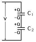
              If you place two in series (C1,2) (see image above) The outer plates have +10 and -10, and the inner plates have +10 and -10. As the outer plates discharge into our other capacitor (previously labled C3,4) the charge is conserved. However the inner plates nullify directly into each other, nullifying charge.

              The outer plates conserve charge shuttling into the other cap, while the inner plates nullify their charge into each other to an extent.


              Thus each time you go into series mode, and discharge a portion, you "loose" some of your total charge...Thus what you have shown is NOT as charge CONSERVING capacitive spring.


              In my proposition, Charge is 100% conserved omitting leakage.

              Comment


              • #37
                Originally posted by Mario View Post
                Hi Jetijs,

                this is actually the next thing I wanted to ask Andrew, maybe moving plates is different than switching caps, then again the calculations seem to work for the switched caps too and reflect what I measured in the real world. So, who knows...

                regards,
                Mario
                Hi guys
                I am following this thread with interest. I think that charging caps and putting them in series and parallel is not the same as physically changing a capacitance of a single cap. There mist ne a difference. To test the concept out I would use a variable capacitor that is made so that it can rotate around full 360 degrees and put a small high speed motor on the shaft. Then I would put this small cap in parallel with a standard cap through a low impedance load (transformer primary). I guess to see the difference with a capacity that small, I would need to use several hundereds of volts.
                Thanks,
                Jetijs
                Hopefully my previous response outlines the difference between proposed systems.

                Cheers!

                Comment


                • #38
                  Originally posted by DrStiffler View Post
                  @Armagdn03

                  People have tried 10k RPM motors driving disks etc., and I have never heard of one going farther than the initial work and observation. Theory look nice, yet what is the missing part?
                  To test the concept out I would use a variable capacitor that is made so that it can rotate around full 360 degrees and put a small high speed motor on the shaft. Then I would put this small cap in parallel with a standard cap through a low impedance load (transformer primary). I guess to see the difference with a capacity that small, I would need to use several hundereds of volts.
                  @DrStiffler
                  @Jetis

                  This is a photo of Chris Carson device. According to Dr. Lindemann...

                  The machine has two sections where stator plates and rotor plates rotate in-between each other, varying the capacitance. These two sections are 180* out of phase with each other, so when the rotor plates are connected to a source of 5,000 volts, and spun at 10,000 rpm, the two sections of the stator produce an AC signal between them. Drawing power from the machine produces no drag on the input motor.
                  http://www.free-energy.ws/images/ccvcg2.jpg

                  If there were a second capacitor, with a load in series, this would be a great rotational candidate for a Charge Conserving Capacitive Spring. Beautiful model, however I do not plan to take the mechanical route, as the limitations are......big.
                  Last edited by Armagdn03; 10-19-2010, 06:06 PM.

                  Comment


                  • #39
                    Hi again guys,

                    Andrew, just trying to be logic: If the theory and calculations we made work for the cap switching setup (in line with my actual measurements), does this mean that theory doesn't apply to your system? Can't work for both if you say your system doesn't have the losses my setup has....

                    About your explanation about the inner plates being the cause of the loss, not sure about that. I just did a few more tests and calculations following the last ones I did. I wanted to replace the C1 in series (0,0235F) of the previous setup with a similar sized cap also charged to 20V, to avoid the inner plates and just have two plates. I didn't have a 23'500uF cap so I used a 47'000uF cap, C2 still being a 94'000uF cap. I made 3 tests with C1 at 3 different voltages discharging into the same C2 @ 10V as the previous setup.

                    1. C1 charged to 20V
                    2. C1 charged to 25V
                    3. C1 charged to 15V

                    I'm not going to rewrite all the calculations but they follow the ones of the previous setup.

                    results:
                    C1 @ 20V: Start energy 14.1 Joules. Charge at end of discharge across the system: 12.527 Joules. Loss: 11.15%

                    C1 @ 25V: Start energy 19.388 Joules. Final charge: 15.862 Joules. Loss: 18.183%

                    C1 @ 15V: Start energy 9.988 Joules. Final charge 9.596 Joules. Loss: 3.92%.
                    The calculations are in line with the measurements I made. This means the losses are not due to the inner plates since C1 in this case is only one capacitor.
                    These tests also confirm what I said about the losses getting bigger the greater the voltage difference between C1 and C2.

                    regards,
                    Mario

                    Comment


                    • #40
                      Originally posted by Mario View Post
                      Hi again guys,

                      Andrew, just trying to be logic: If the theory and calculations we made work for the cap switching setup (in line with my actual measurements), does this mean that theory doesn't apply to your system? Can't work for both if you say your system doesn't have the losses my setup has....

                      About your explanation about the inner plates being the cause of the loss, not sure about that.

                      regards,
                      Mario
                      Mario,

                      My setup has losses, like all do, leakage etc. When I spoke of a difference between the two I was referring to the loss of charge due to the direct action of the circuit. The capacitor switching device nullifies part of its charge as the series connected capacitors are discharged. This can be shown looking at this sheet again.

                      http://i210.photobucket.com/albums/b...tyswitcher.jpg

                      As you can see the system starts out in equilibrium with a charge of 200 coulombs. Durring the next cycle we have 150 coulombs, and we end at 180 coulombs. As you can see the charge does not stay constant through the cycle.

                      Also note that begining = 200q and ending state = 180q, so where did the 20q go?

                      When one set of caps is switched to series configuration, it goes from having 100 coulombs on it to 50 across it with a doubling of voltage bringing it 20v. When discharged into the second cap (of parallel configuration) the voltage drops from 20v, to 12v.

                      The difference in potential is obviously 8v,

                      If we only look at the series configured cap, we have 2.5Farads, and an 8v loss...Q=VC so, 2.5c*8v = 20 coulombs. Thus, the 8v drop caused a 20 coulomb loss in this capacitor.

                      The other capacitor is at 10f and 12v giving it a 20 coulomb gain.

                      however when we continue to work through,

                      Now we switch it back to parallel, giving it 6v @ 10farads = 60 coulombs

                      The parallel cap is siting at 12v @ 10 farads, = 120 coulombs

                      Combined = 60c + 120C = 180C total when all is said and done. The 20 coulombs lost from switching to series follows through to the end, for a loss of 20 coulombs for the cycle. This means that when the next cycle starts, there is less than there was previously to work with, constituting loss.


                      Think good and hard about why switching to series makes 50% of the charge appear to go missing. About how any apparent loss of coulombs from this state, is actually Doubled, since what ever is lost on the outer plates is also nullified on the inner plates as they discharge directly into, nullifying one another. (example, parallel cap has 100q, switched to series it has 50q, discharge 20 of that and you have 30q. Switch back to parallel and you will have 60q only. Though you lost 20 in series, you really lost 40 total.


                      In my version however, the charge stays 100% the same through the ENTIRE process, since there is no series switching, no charge can ever be nullified.

                      Comment


                      • #41
                        Andrew, ok. But did you read the whole last post I made? I replaced C1 comprised of two caps by C1 made of only one cap. No inner plates, and when I discharge this cap to C2 I still have the losses I had in the previous setup. Please read my last post and tests again.

                        I also repeat the question: If the theory and calculations work for my setup (and they do since measurement confirmed it), does it mean they don't apply to yours since you don't seem to have losses except minimal ones? How can the same theory support both our systems?

                        regards,
                        Mario

                        Comment


                        • #42
                          Originally posted by Mario View Post
                          Andrew, ok. But did you read the whole last post I made? I replaced C1 comprised of two caps by C1 made of only one cap. No inner plates, and when I discharge this cap to C2 I still have the losses I had in the previous setup. Please read my last post and tests again.


                          regards,
                          Mario
                          @ Mario,

                          There will always be loss whenever a cap is discharged into another cap, this is not my argument.

                          My arguement is that action and reaction are separated by time with my setup, so that they may both be used.

                          step 1. Rise the energy state of the system. Work is accomplished. Work input = work output.

                          Step 2) let the system free, and let it return to its own equilibrium. again work is accomplished.

                          note: The energy of my system is exactly the same when the process is completed as when it started. If you start with X volts and Y joules, you end with X volts and Y joules.

                          When the capacitor switching system completes one cycle, it is at a lower energy state than it began, that is a large clue as to how these are very different systems.

                          I also repeat the question: If the theory and calculations work for my setup (and they do since measurement confirmed it), does it mean they don't apply to yours since you don't seem to have losses except minimal ones? How can the same theory support both our systems?
                          You are correct. What applies to yours, does not apply to mine and vice versa. I wanted to work on what you proposed anyways because it is similar, but I could not pin point why charge went missing for a bit. Once I did you can see that I posted that they were not the same, and the same maths, analysis can not be used. As for theory, one theory should describe everything, but different things will have different explanations!

                          Armagdn03:
                          Thus each time you go into series mode, and discharge a portion, you "loose" some of your total charge...Thus what you have shown is NOT as charge CONSERVING capacitive spring.
                          Your method allows a nullification of charge, mine does not, therefore they are fundamentally different.

                          Comment


                          • #43
                            Why not?

                            Originally posted by Armagdn03 View Post
                            @ Mario,

                            There will always be loss whenever a cap is discharged into another cap, this is not my argument.

                            My arguement is that action and reaction are separated by time with my setup, so that they may both be used.

                            step 1. Rise the energy state of the system. Work is accomplished. Work input = work output.

                            Step 2) let the system free, and let it return to its own equilibrium. again work is accomplished.

                            note: The energy of my system is exactly the same when the process is completed as when it started. If you start with X volts and Y joules, you end with X volts and Y joules.

                            When the capacitor switching system completes one cycle, it is at a lower energy state than it began, that is a large clue as to how these are very different systems.


                            You are correct. What applies to yours, does not apply to mine and vice versa. I wanted to work on what you proposed anyways because it is similar, but I could not pin point why charge went missing for a bit. Once I did you can see that I posted that they were not the same, and the same maths, analysis can not be used. As for theory, one theory should describe everything, but different things will have different explanations!


                            Your method allows a nullification of charge, mine does not, therefore they are fundamentally different.
                            Why not do the twin variable cap setup and loose nothing except for the losses in the small traces that are linking the caps. Have two caps as tanks and use the variable caps to slosh the bucket so to say and generate from the side to side motion you create with the variable caps. It would be like a 10 foot bucket with a small radius. Only variate a small portion on the top. If the caps were of a higher quality I bet you would loose little from the process. You could even design a way to make the variable cap better as well by vacuum or oil filled methods. With the oil filled the best in dielectric strength but slower to turn.

                            Comment


                            • #44
                              Originally posted by Jbignes5 View Post
                              Why not do the twin variable cap setup and loose nothing except for the losses in the small traces that are linking the caps. Have two caps as tanks and use the variable caps to slosh the bucket so to say and generate from the side to side motion you create with the variable caps. It would be like a 10 foot bucket with a small radius. Only variate a small portion on the top. If the caps were of a higher quality I bet you would loose little from the process. You could even design a way to make the variable cap better as well by vacuum or oil filled methods. With the oil filled the best in dielectric strength but slower to turn.
                              you are spot on.

                              Two variable capacitors would be ideal for increase in power output, however for sake of simplicity, and ease of explanation, I am describing the system with only one variable capacitor.

                              I have designed my own special variable capacitance for this. It requires no moving parts, however the voltage across my system is 10KV - 12KV before the decrease in capacitance takes place, meaning that even with good insulation, leakage will be something to watch.

                              Comment


                              • #45
                                Originally posted by Armagdn03 View Post
                                you are spot on.

                                Two variable capacitors would be ideal for increase in power output, however for sake of simplicity, and ease of explanation, I am describing the system with only one variable capacitor.

                                I have designed my own special variable capacitance for this. It requires no moving parts, however the voltage across my system is 10KV - 12KV before the decrease in capacitance takes place, meaning that even with good insulation, leakage will be something to watch.
                                Ok there is a big difference in a single variable cap and twin ones. One would be harmonic(twin) and the other non harmonic(single). The harmonic one would be like putting a teeter tawter in the system and the other would be like jacking the one side up. The harmonic one would be the less leaky since it would have an increase with the associated decrease on the other side. This would make it more powerful as well and you wont have to have extreme high voltages like you are talking then.
                                On the subject of leakage you could always shield any wires with static shielding(not connected to anything) This would reflect the leaks back to the source of the leak and contain it better especially if you stay with higher voltages. Cheap static shielding would be a heavy aluminum foil tape or just foil glued onto the wires. If you do them in bands and overlap the bands it should make an effective static shielding for your high voltage app..
                                Also drop by our thread in the "don't kill dipole" I am working on the same kind of system to get an ac output with a high voltage pair of leyden jars type setup with twin variable caps on a motorized rotor. Weather or not this will work it would be nice to have your setup to compare to as well.
                                Last edited by Jbignes5; 10-20-2010, 05:36 PM.

                                Comment

                                Working...
                                X