Announcement

Collapse
No announcement yet.

Charge conserving Capacitive Spring.

Collapse
X
 
  • Filter
  • Time
  • Show
Clear All
new posts

  • #76
    I found a link for home-made super caps which caught my eye.
    Re:Home made supercaps - UltraCapacitors.org - Ultra Capacitor - Super Capacitors - Super Battery?
    If we rotate the plates the capacitance will jump from a very small value to a f***ing huge one (The author claims 25F. Even 1 Farad would be awesome but 25!) While mechanical it still could yeild very large changes in capacitance very quickly (well depending on the RPM of your motor). Anyone else's comments would be very much appreciated as part of me still feels like I can't believe what I am seeing.
    Scribd account; http://www.scribd.com/raui

    Comment


    • #77
      Originally posted by Armagdn03 View Post
      This is an excellent question to brainstorm! I really think the hidink method is great, but requires very high voltage.

      Ideas???

      Ill get the ball rolling,

      Think electrostatic speaker used in reverse. acoustically drive the capacitor, rather than using the capacitor to create an acoustic signal. Flexible membranes at the end of a tube driven at resonance.
      I had never heard of an electrostatic speaker until you mentioned it in this post. Its physics of operation sure makes you wonder how mainstream science pushed the dielectric field into obscurity.

      Does anybody have an electrostatic speaker that would be willing to do some compression tests on to figure out the the general range of capacity?

      Can you describe in a bit more detail the youtube video that you posted: YouTube - ‪Armagdn0303's Channel‬‏

      There may be a page somewhere describing this, but I just don't see it. How is that capacitor tube hooked up to those meters? Where are you feeding your voltage to? What materials are you using?

      Thanks,

      Dave
      Last edited by Web000x; 12-13-2011, 06:47 PM.

      Comment


      • #78
        Originally posted by Raui View Post
        I found a link for home-made super caps which caught my eye.
        Re:Home made supercaps - UltraCapacitors.org*-*Ultra Capacitor - Super Capacitors - Super Battery?
        If we rotate the plates the capacitance will jump from a very small value to a f***ing huge one (The author claims 25F. Even 1 Farad would be awesome but 25!) While mechanical it still could yeild very large changes in capacitance very quickly (well depending on the RPM of your motor). Anyone else's comments would be very much appreciated as part of me still feels like I can't believe what I am seeing.
        I'm confused where you saw this? I read the whole thread and didn't see anything about rotating the plates. But as far as doing that, in my opinion there would be a variance in capacitance because of vortex/centrifugal/centripetal forces on the electrolyte, and with charged particles/ions rotating there are magnetic fields set up adding completely new parameters to the system.

        Comment


        • #79
          Unless I'm confused the capacitance comes from the black material. So simply rotating the plates like a variable cap will produce a variable super cap. I may have missed the mark but that was my analyiss on how it worked.

          Raui
          Scribd account; http://www.scribd.com/raui

          Comment


          • #80
            Originally posted by Web000x View Post
            I had never heard of an electrostatic speaker until you mentioned it in this post. Its physics of operation sure makes you wonder how mainstream science pushed the dielectric field into obscurity.

            Does anybody have an electrostatic speaker that would be willing to do some compression tests on to figure out the the general range of capacity?

            Can you describe in a bit more detail the youtube video that you posted: YouTube - ‪Armagdn0303's Channel‬‏

            There may be a page somewhere describing this, but I just don't see it. How is that capacitor tube hooked up to those meters? Where are you feeding your voltage to? What materials are you using?

            Thanks,

            Dave
            The construction of the tubes in that video are very simple.

            Take the tube, paint with adhesive. Place two sections of tin foil covering each half of the tube so that they are electrically separate (the black tape shows spearation). And now you are done!

            The capacity meter is connected to the two foil sections. When the plasma is active it acts as a parallel plate capacitor, when not active, it shows the the free space capacity of the plates.

            The volt meter is connected across the tube to show the various breakdown voltages.

            It took me 30 minutes to make about 8 tubes.

            Comment


            • #81
              Andrew,

              I just got a new job traveling the country working on automated packaging equipment so I've been slow to get to replicating one of your solid state switching tubes. I just finished replicating a tube and got some different results.

              When you reached your breakdown voltage of 175, did you measure the current into the fluorescent tube?

              My tube breakdown voltage happens when my 4 uF cap charges up to about 500V. Once the gas is sufficiently conducting, the voltage drops to about 50 volts and draws about 150 mA for a power equaling 7.5 watts. Unless I can find a way to vastly increase capacitance variation, I don't know if this tube can be considered practical for our purposes.

              I used approximately the same size tube and sections of foil.

              My capacitance is right on the mark with yours as far as variation goes, but I'm curious how you got light from that tube at 175 volts. What brand tube did you use?

              Did your power consumption vs. capacity variation seem practical?

              I would test this myself but am not sure I have the same type of tube as you. Does paralleling multiple tubes cause an x-fold(2x,3x,4x,etc) increase in current?


              Thanks,

              Dave
              Last edited by Web000x; 12-13-2011, 06:48 PM.

              Comment


              • #82
                Originally posted by Web000x View Post
                Andrew,

                I just got a new job traveling the country working on automated packaging equipment so I've been slow to get to replicating one of your solid state switching tubes. I just finished replicating a tube and got some different results.

                When you reached your breakdown voltage of 175, did you measure the current into the fluorescent tube?

                My tube breakdown voltage happens when my 4 uF cap charges up to about 500V. Once the gas is sufficiently conducting, the voltage drops to about 50 volts and draws about 150 mA for a power equaling 7.5 watts. Unless I can find a way to vastly increase capacitance variation, I don't know if this tube can be considered practical for our purposes.

                I used approximately the same size tube and sections of foil.

                My capacitance is right on the mark with yours as far as variation goes, but I'm curious how you got light from that tube at 175 volts. What brand tube did you use?

                Did your power consumption vs. capacity variation seem practical?

                I would test this myself but am not sure I have the same type of tube as you. Does paralleling multiple tubes cause an x-fold(2x,3x,4x,etc) increase in current?


                Thanks,

                Dave
                fantastic questions.

                Really all that remains here is an engineering work-through.

                When the tubes activate their plasma, the region between the electrodes becomes immediately conductive. This causes your capacitor to dump its load to a point where the plasma is no longer able to sustain. However, it is not necessary to discharge all that built up charge. Really we just want to oscillate our voltage around the region of most change in capacitance per volt. Note where the largest change occurs, then build a circuit which oscillates around this voltage.

                For example, imagine a 1 uf cap charged to 175 volts (breakdown or plasma) when the threshold is reached, it discharges all 1 uf worth of charge.

                You could reach the same 175v much quicker using a 1mf cap. The discharge would be much much quicker, less charge expended per unit time, and so frequency would rise also. You get more oscillation around the region wanted, for less charge per unit time expenditure.

                think about all the variables and what changing each does. Think about how little energy is expended using a one way tank circuit like shown in Imhoteps radiant oscillator thread to light CFL's. Just re design so that you are not going for max lumens, rather max capacity change.

                Comment


                • #83
                  Check out patent US Patent 4127804

                  This patent belongs to the feds.

                  Electrostatic energy conversion system

                  This is the exact same mechanism as Chris Carson's Device, a variable capacitance generator.

                  This patent was granted to Onezime Breaux based on "research" from John Trump from MIT.

                  From William Lyne-

                  "Dr. John G. Trump was the main government official who went over Tesla's secret papers after his death in 1943. At the time, Trump was a well-known electrical engineer serving as a technical aide to the National Defense Research Committee of the Office of Scientific Research & Development, Technical Aids, Div. 14, NTRC (predecessor agency to the CIA's Office of Scientific Intelligence). Trump was also a professor at M.I.T., and had his feelings hurt by Tesla's 1938 review and critique of M.I.T.'s huge Van de Graaff generator with its two thirty-foot towers and two 15-foot diameter balls, mounted on railroad tracks—which Tesla showed could be out-performed in both voltage and current by one of his tiny coils about two feet tall. Trump was asked to participate in the examination of Tesla's papers at the Manhattan Warehouse & Storage Co.

                  Trump reported afterwards that no examination had been made of the vast amount of Tesla's property, that had been in the basement of the New Yorker Hotel, ten years prior to Tesla's death, or of any of his papers, except those in his immediate possession at the time of his death. Trump concluded in his report, that there was nothing that would constitute a hazard in unfriendly hands. Dr. John G. Trump, evidently used Tesla's idea's and incorporated them into his turbines, after WW11, while at MIT as Dr.Tesla's knowledge on radioactivity, and his views were well known since the days of radium, and Madam Curie.

                  The turbine motors resemble the variable capacitors used in tuning a radio set, except the rotors can spin around continuously, instead of intermeshing with a stationary plate, to tune in a station. In the simplest version, a radioactive isotope coated plate emits beta rays (electrons) in a vacuum, between two ordinary plates of metal on a shaft. The electrons fly out at high speeds and strike the surrounding metal plates , thus endowing them with a negative charge. The charge builds up until the uncoated plates reach a voltage corresponding to the kinetic energy of the electrons. If the electrons are ejected from the isotope with a speed corresponding to a million volts, they would be able to fly to the opposite plate in the face of a field of a million volts. In the simplest fashion an electric load is connected to the coated and uncoated plates to run some kind of DC motor. "


                  So Trump was able to see all of Tesla's work after he died, work that is still classified to this very day above atomic bomb information.

                  Tesla as shown earlier also did work with electrostatic variable capacitance generators (circa 1890).

                  You have to conclude this device is Tesla's child, stolen from him by John Trump as he went over most of Tesla's papers.
                  Last edited by SilverToGold; 06-13-2011, 06:24 PM.

                  Comment


                  • #84
                    I just found out that John Trump is Donald Trump's uncle.

                    ” The second storm–terrorism: We need to get past the idea that, because we’re the only superpower, we’re safe. My uncle John Trump was an MIT professor and a brilliant man. He had a clear and compelling view of the future, including a strong belief that one day the United States might be subjected to a terrorist strike that would turn Manhattan into Hiroshima II. I always respected Uncle John, but sometimes found myself wondering if maybe he wasn’t exaggeration just a bit.

                    Today we know that John Trump knew exactly what he was talking about.

                    So what are we doing about this threat? Are we getting tough with people who would wipe us out in a second? Hell no.”

                    –Donald Trump, p.26, The America We Deserve, 2000

                    It all makes sense now!

                    Comment


                    • #85
                      I found a fairly lengthy report from John Trump about this technology. The first paragraph reads;

                      "This report describes an investigation of the electrical
                      engineering possibilities of machines depending on electrostatic
                      forces and principles and utilizing high vacuum as the essential
                      insulating medium. This combination of electrostatic devices and
                      vacuum insulation makes possible, it is believed, a new type of power
                      system - capable of all the functions of modern power systems, but
                      possessing unusual ultimate advantages in power capacity, overall
                      efficiency, distance of transmission, reliability, and economy
                      ."

                      I recommend it and it is avaliable here; Vacuum Electrostatic Engineering - John G. Trump

                      Peace,
                      Raui
                      Scribd account; http://www.scribd.com/raui

                      Comment


                      • #86
                        Great link Raui.

                        Here's a patent application that is once again the same mechanical variable capacitance generator. This one has actual data in it and claims 12 kW of power at 1600 Hz (see page 8). I'm sure it takes less than 12kW of power to rotate the rotors at 1600 Hz

                        United States Application US20090066298

                        ELECTROSTATIC GENERATOR/MOTOR

                        There is some very interesting data in this patent.

                        AGAIN, this patent belongs to the DOE. I wonder why the Feds find this technology so interesting. LOL!
                        Last edited by SilverToGold; 06-13-2011, 04:59 PM.

                        Comment


                        • #87
                          Originally posted by Raui View Post
                          I found a fairly lengthy report from John Trump about this technology. The first paragraph reads;

                          "This report describes an investigation of the electrical
                          engineering possibilities of machines depending on electrostatic
                          forces and principles and utilizing high vacuum as the essential
                          insulating medium. This combination of electrostatic devices and
                          vacuum insulation makes possible, it is believed, a new type of power
                          system - capable of all the functions of modern power systems, but
                          possessing unusual ultimate advantages in power capacity, overall
                          efficiency, distance of transmission, reliability, and economy
                          ."

                          I recommend it and it is avaliable here; Vacuum Electrostatic Engineering - John G. Trump

                          Peace,
                          Raui
                          Really interesting document, I have read about the first 50 pages or so, and have had alot to think about. Let me read the rest and get back.

                          Comment


                          • #88
                            Originally posted by SilverToGold View Post
                            Great link Raui.

                            Here's a patent application that is once again the same mechanical variable capacitance generator. This one has actual data in it and claims 12 kW of power at 1600 Hz (see page 8). I'm sure it takes less than 12kW of power to rotate the rotors at 1600 Hz

                            United States Application US20090066298

                            ELECTROSTATIC GENERATOR/MOTOR

                            There is some very interesting data in this patent.

                            AGAIN, this patent belongs to the DOE. I wonder why the Feds find this technology so interesting. LOL!
                            Keep up the good detective work, all good examples that can be suited to this purpose.

                            Comment


                            • #89
                              Whenever I conceive of a concept, I pay a mental game, and re evaluate the concept by imagining its inverse.

                              For example,

                              If we take a capacitor and separate its plates, we decrease its capacitance, but we DO NOT INCREASE its energy state.

                              If we take a CHARGED capacitor and separate its plates, we decrease its capacitance and INCREASE its energy state.

                              Similarly we can change the permeability of an inductors core, and we DO NOT change its energy state

                              But we can change the permeability of a CHARGED inductor core, and affect a change!

                              Let me elaborate on this concept.....

                              Comment


                              • #90
                                Originally posted by Armagdn03 View Post
                                Whenever I conceive of a concept, I pay a mental game, and re evaluate the concept by imagining its inverse.

                                For example,

                                If we take a capacitor and separate its plates, we decrease its capacitance, but we DO NOT INCREASE its energy state.

                                If we take a CHARGED capacitor and separate its plates, we decrease its capacitance and INCREASE its energy state.

                                Similarly we can change the permeability of an inductors core, and we DO NOT change its energy state

                                But we can change the permeability of a CHARGED inductor core, and affect a change!

                                Let me elaborate on this concept.....
                                One can charge an inductor (with core) by running current through the windings which will be a dynamic process. Changing the core permeability during this dynamic process requires specific timing, too difficult.

                                We can create a static magnetic tension in the core using magnets.
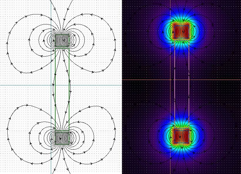
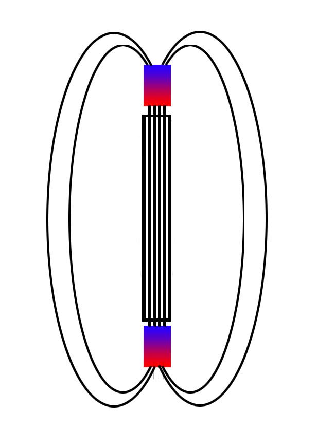
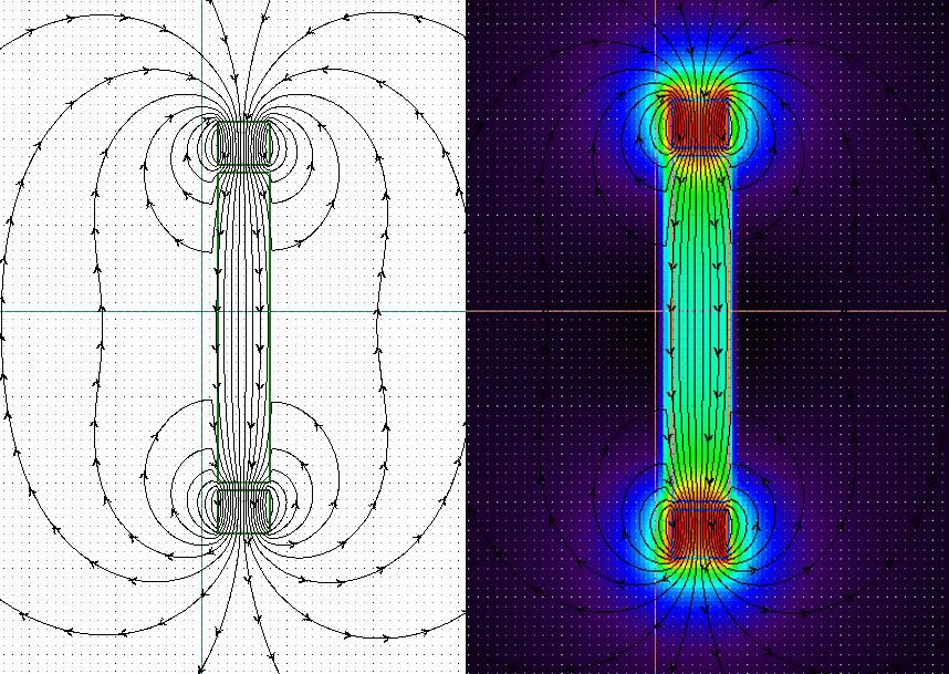
                                In the image below, you can see the core charged with magnetic lines of flux,


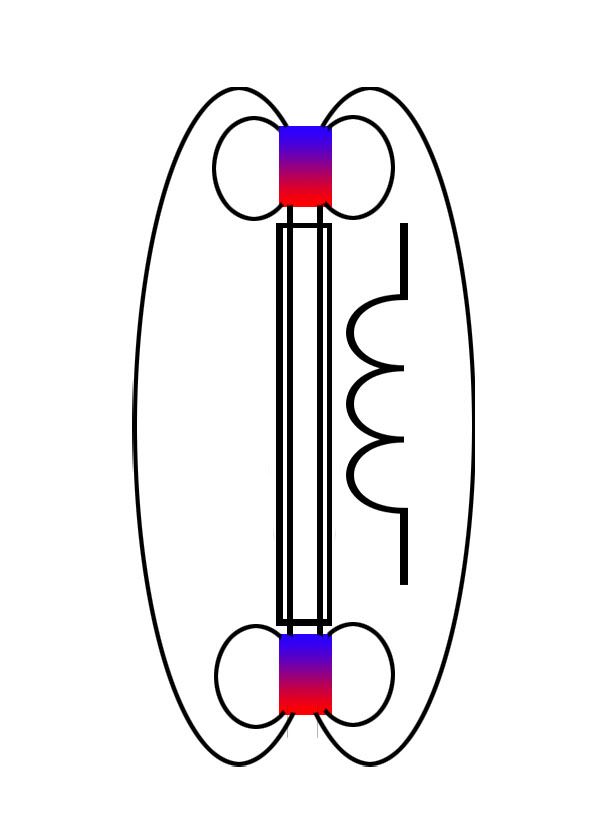
                                Creating a change in the permeability of the core (reduction in this case) causes a change in the amount of flux the core can physically hold. I in the photo below, I have drastically reduced the permeability of the core. Notice that the flux lines no longer overtone to create a unified magnetic field, but rather circle around themselves to create two magnetic fields. The flux density of the core is drastically reduced.


                                By changing the permeability of the core, we have affected the coherent flux density within the core of our inductor.

                                Here is another photo to show this. In the first photo, 4 loops of magnetic flux are supported within the core.


                                Now we change the permeability of the core so that only two flux lines are supported. The remaining two circle around their respective magnets rather than over-toning.


                                Notice in the image above, I have included the windings of the inductor. When the permeability of its core changes, the coil sees a change in magnetic flux with respect to time...and EMF is induced.

                                Now think about this....The Lenz effect, is still present, but it is pushing against static magnets, the change in flux was not caused by the relative motion of conductors and lines of flux, rather through a change in flux density by altering the permeability of the core.

                                Comment

                                Working...
                                X