Announcement

Collapse
No announcement yet.

Overunity Heating/Cooling Using the Peltier Device

Collapse
X
 
  • Filter
  • Time
  • Show
Clear All
new posts

  • #16
    EgmQC,
    your almost right about that.

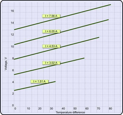
    Peltier's do not have a linear I*V curve though.

    They are also not the most efficient at max thermal displacement,
    they have a sweet spot a little over 2/3 to max V allowed.

    But reading all this I noticed one thing missing.

    The potential thermal differential from anode to cathode.

    Elias, you have presented very good talking points,
    not many have noticed that their P/N junctions
    respond efficiently to split shared thermal duty,
    unlike resistive (watseful) heater arrangements.


    I made beer cooler "Mugs" for people in my step-family.

    I used induction transfer so the mugs
    didn't need to be plugged in every time
    the darned beer was set down.

    Similar to the way toothbrush's are charged
    when set down on their charging base.

    A wallWart to a heavier short coil in the base,
    a longer slightly lighter gauge coil in the mug base.

    But the beer would only get so cold,
    even though the Peltier was running
    just above the 2/3 V point.

    The solution to increase the thermal differential,
    is to put two peltier's physically in series.

    when you take a thick metal square
    that has a reasonable amount of mass to it
    and place it between two peltiers + and -.

    You wind up with it electrically in series,
    but more importantly you have now increased
    the available potential thermal difference available.

    Yes, you increase the V X2 to maintain proper I,
    but you now have about 80% more thermal differential.

    I wound up using two smaller peltiers instead,
    conductive epoxy for the two peltier/plate joints,
    connected the leads together too for good measure,
    and fed the remaining two end leads to the
    induction coil already in the beer mug base.


    Moral to this,
    and my point is.

    They can be put both
    electrically AND mechanically in series
    to obtain better results and efficiency overall.

    No, you don't get a full extra 100% with two,
    my napkin-math was just under 80% with a second one.

    I made a personal desk AC from
    two huge eBay honkers later,
    same principle, awsome results.
    (8" muffin fan full boar = 46 degree air in a 78 degree room)

    My plate was 1/2" thick copper because I was afraid
    of a thermal transient due to one creating greater
    thermal differential faster than the other one,
    causing premature failure in the second one ...

    These:
    Gigantic 62mm - 545 Watt Thermoelectric Peltier Cooler - eBay (item 310135040904 end time Dec-02-10 05:47:44 PST)

    Please note, these are not good ones,
    there are better out there for sure ...

    But you get my point.


    Oh, and in the extreme magnetic field
    of a Pantone/GEET assembly they shine.

    They produce from both the heat and the field,
    as Tutanka has indicated above.

    They do not seem to do this as well
    from regular coil/magnet fields my opinion.

    Remember that peltiers made to generate electricity
    are made and rated for a much higher temperature !

    And that condensation is the enemy,
    pot thyne apparatus well my son. LOL

    Ask anyone that forgot to seal the edges of
    a peltier CPU cooler arrangement before use ...

    Anyway, just fodder for thought,
    sorry for the crappy spellin'
    Last edited by WeThePeople; 11-04-2010, 07:49 AM.

    Comment


    • #17
      Originally posted by EgmQC View Post
      Why did you assume that the current draw will be 10 time less with 10 device ? The reality should not be (12v * 10Device) * 4Amps = 480W ? When you put thing in series , the amperage doesn't change but the input voltage need to be higher to compensate for the voltage drop , so 10 device who each one need 12v will require 120v input , the same thing happen if you want a example with light bulb , if you put 10 120v light bulb in series , you will need a voltage of 1200v to make them fully bright because of the voltage drop across each one. 100W light bulb is 0.833Amp , so 10 in series will be 1200v at 0.833Amp in this example.

      Maybe i missed something its why i ask you.
      Best Regards,
      EgmQC
      Hi

      You are right about that, this hypothesis is only correct if there is a linear V-I relationship for the device, and this requires careful experimentation of course. I don't have a Peltier device at hand so I cannot verify it right now. But ... I did quite a search and you know the diagram I posted above indicates that the V-I relationship is quite linear. Even in diodes the forward biased state, there is a range of linearity, and if we want to make these devices operate more efficiently we must find the interval of linearity and work in the lowest possible current draw in that region.

      This is the chart:


      Elias
      Humility, an important property for a COP>1 system.
      http://blog.hexaheart.org

      Comment


      • #18
        "Sweet-Spot"

        So, 'rated' voltage for these units I have is 12v, and as they are intended for use in cars, actually just over 14v, (output of alternator). 2/3 of 14 is 9.
        If I stack all 4 together, 36 volts, 3- 12v batteries, should be about right.
        If I'm understanding correctly, I should put a conductive thermal mass, (1/2" thick copper plate) between the units, bonding the 'hot' side of 1 peltier to the plate, and the 'cold' side of the other, to the other side.I wonder if I should increse the size/capacity of the 'cooling' fan on the outside 'hot' side? Or maybe use 2?
        I got 4 12v. (input) 15kv (output) negative ion generators, from the same source. Any idea what running them in close proximity to the peltiers would do?Burn them out, make them more efficient, have no effect?Jim

        Comment


        • #19
          Originally posted by dutchdivco View Post
          So, 'rated' voltage for these units I have is 12v,
          and as they are intended for use in cars,
          actually just over 14v, (output of alternator).
          2/3 of 14 is 9.
          If I stack all 4 together,
          36 volts, 3- 12v batteries,
          should be about right.
          Observe both the operating and maximum
          voltage ratings as a starting point.

          The 2/3 "Sweet Spot" is from when running them
          at the top end of the acceptable thermal range
          in the application of cooling PC CPU's while
          overclocking the panties off the poor things.

          The source (CPU) side is really hot,
          and the sink side not exactly cool either.

          Not the ideal application enviroment
          or operating range of use for them.

          So there becomes a turning point when
          the heat that your trying to move/remove
          added to the heat generated by the current
          being forced through the Peiltier to function
          causes diminishing returns and is less efficient.

          Although we all strive to run all and any
          semiconductor junctions in the "Linear Region",
          except maybe guitar fuzz pedals, etc.

          In real life applications of these Peltiers,
          they do not do what those graphs indicate
          except in ideal test conditions of course.

          The total thermal differential indicated
          is at ideal test in/out parameters only.

          I ran rated V on the two in the beer mugs,
          and about 3/4 V on the desk air conditioner...


          Originally posted by dutchdivco View Post
          If I'm understanding correctly,
          I should put a conductive thermal mass,
          (1/2" thick copper plate) between the units,
          bonding the 'hot' side of 1 peltier to the plate,
          and the 'cold' side of the other, to the other side.
          Yes, hot side of one Peltier,
          to the cold side of the other,
          just like stacking batteries.

          Clamped very well with a good thermal paste
          like "Arctic Silver" for CPU's as example,
          or some thermal epoxy for permanant installs.
          (Use Google/eBay)

          I had that copper billet left over
          from something I was machining before,
          and I am known for overkill on stuff.

          Think what your putting between them
          as a flywheel instead for ease of concept.

          Just as a flywheel tames sudden RPM increase/decrease,
          you need something of reasonably high mass here
          to keep the junction point of those two peltiers
          from changing temperature to fast and failing.

          If not,
          one might achieve to low temperature differental across it,
          leaving the other to achieve to high a differential and fry.


          On the other point.

          The thermal mass used between two Peltiers
          must be a very good thermal conductor,
          but need not be electrically conductive.

          I (Remember overkill?) liked having both
          the copper and conducting epoxy as one path,
          and the two leads connected together as another.

          I used both the heatsink and the Peltier's lead
          connected together for best conductivity
          on each end of my PEV-AC as example,
          and the copper plate with two Peltier leads
          as the center tap conductor as example.

          No need to get that drastic
          like I tend to do on this stuff...

          That your indicating using
          a battery stack is good to.

          You could use two batteries in series,
          to feed two Peltiers in series instead.

          Putting Peltiers in series is a gamble,
          your betting that one Peltier will have
          the same voltage differential across it
          as the second one will too during use.

          In practice you need to run the one
          that draws a little more than the other one
          on the hotter side of the Peltier stack,
          leaving the one that draws less during testing
          to be the one on the cooler side of the stack.

          That is a personally tested fact.

          But if possible,
          use the center tap method.


          Originally posted by dutchdivco View Post
          I wonder if I should increse the size/capacity
          of the 'cooling' fan on the outside 'hot' side?
          Or maybe use 2?
          Use intuition and caution on this one,
          Peltiers are not forgiving for sure.

          If they can move it (Thermals),
          you must remove it continuously
          or catastrophic failure will occur.

          best advise is skip the batteries
          for the initial prototype testing,
          and test with variable DC somehow.


          Originally posted by dutchdivco View Post
          I got 4 12v. (input) 15kv (output)
          negative ion generators, from the same source.
          Any idea what running them in close proximity
          to the peltiers would do?Burn them out,
          make them more efficient,
          (or) have no effect?
          You know what a diode is...

          Just picture an entire X/Y grid
          of many diodes between two plates.

          Thats all these are.

          Just rows and columns of many
          doped semiconductor junctions
          lined up like army men between
          two conductive plates that are also
          the source & sink for the thermal exchange.

          You have the advantage here that
          all of them are connected in parallel,
          so transients are less likely to cause failure.

          Sounds like you making a combo
          HV ionic air cleaner & AC unit.

          Nice !

          Comment


          • #20
            Elias, your on the right track.

            The law of diminishing returns with these
            that causes them to become less efficient
            when the application is to remove heat,
            become a benifit when the desired result is
            to make heat efficiently in the first place.

            You will have excess energy your unable to utilize real-time,
            with wind, solar, and other sources as example.

            What to do with that has always been an issue,
            store to battery, store as heat, etc.

            I would like to see this applied there somehow.

            the trick to using these as a heater
            to the best of their ability would be
            to keep the entire source plate
            at a constant temperature,
            so the sink plate maintains the maximum
            temperature differential the part can yield.

            I know of only one thing that can do that,
            water...

            Peltiers have been used to heat water before,
            but I have never read of them being used
            the other way around instead.

            If you take, say, a 5-gallon plastic piant pail,
            and fill it with water to the top.

            Use the pail's lid to mount a finned "heatsink"
            with fins down into that water, fins fully wet.

            mount a second heatsink on top of the lid
            with fins pointing up instead and a fan on it
            with the peltier between them to do the work.

            It would sure take a long time to cool down
            that water down to any appreciable degree !

            Yet the peltier would maintain a nice combination
            of the thermals derived from the water to the air,
            and the waste thermals generated internally across
            all the P/N junctions in the peltier from the current.

            Win-Win

            One of the things that makes mechanical heat pumps efficient
            is that they are encapsulated motor/compressor sealed units
            that scavange the heat wasted from the current in the motor,
            and the heat from the compressor's operating friction,a
            and the latent heat from compressing the refrigerant too.

            They cool rather fair, but they heat really excellent.

            Nice idea sir.
            Last edited by WeThePeople; 11-05-2010, 03:37 AM.

            Comment


            • #21
              "The 2/3 "Sweet Spot" is from when running them at the top end of the acceptable thermal range in the application of cooling PC CPU's while
              overclocking the panties off the poor things."
              I don't know if this is relevent to what your saying here, but the units I have weren't made for cooling CPU's; They are about 6"x6" x 3", and were made for auto refrigerators.i.e a small unit used to keep drinks and maybe a small amount of food cold during trips.I don't know if the stated operating perameters are endagering their panties or not.
              Yes, 1 use would be an 'air conditioner', to cool and ionise the air for the 'cabin' of an auto, or even a small room.
              Also might be used as an ICE, (Infernal Combustion Engine) intake.Something like a 'cold air intake'.A duct or tube, air would enter, and pass thru an area where 1 or more discharge needles from ionisers project into airstream. Firstly, any particulates would be electrostatically bonded to the inside of the tube, and removed from the airstream.So, air would be 'filtered', without any restriction, as normal filtering does.Second, any H2O molecules in the air would be split into hydrogen and oxygen, and air would be totally dry (de-humidified). If water vapor 'occupies' the same space as vaporised fuel, dehumidified air would be able to 'absorb' more fuel? Only vaporised fuel burns.Certainly more O2 and hydrogen wouldn't hurt combustion.Could even increase H and O levels with water injection 'upstream' of ionisers.Or, if totally dry air was not beneficial, could use water injection downstream of ionisers.Air would still be richer in O2 and hydrogen than normal aptnopheric air, and without particulates. Anyway, then peltiers cool air, making it denser. The reason for Cold air intakes is denser air expands more during combustion, yielding more power. Anyway, those are applications I'm thinking right now.Jim

              Comment


              • #22
                I have some 1" thick aluminum, also 'left over' from another project. Wonder if I should insulate the edge, all the way around?

                Comment


                • #23
                  Originally posted by dutchdivco View Post
                  I have some 1" thick aluminum,
                  also 'left over' from another project.
                  Wonder if I should insulate the edge,
                  all the way around?
                  Aluminum is interesting stuff.

                  It conducts thermals very well, and fast too.

                  But it can be overcome to easily across thick pieces.

                  So at a 1" thickness like that,
                  one side could manage to get to hot without
                  transferring sufficient thermals to the other.

                  Also, it would be the lightest "Flywheel" you could use.

                  Think of it this way,
                  how long would it take for a torch to heat it.

                  Aluminum, near instant,
                  copper, a lot longer,
                  steel, longer still.

                  The idea is to transfer heat well enough,
                  but transition from cool to hot slowly too.

                  Jugglin' act really.


                  Potting the aluminum edging would not be necessary.
                  (Or did you mean electrically insulate the edges ?)

                  Potting the edges of the actual Peltier junctions
                  has most likely been done for you already,
                  as this is finished goods ready for use.

                  But if it has not been done yet,
                  it is strongly advised you do so.

                  Any indication of what current these draw yet?


                  On the other HV ionic charge/cling idea,
                  electrostatic painting comes to mind.

                  Comment


                  • #24
                    Thanks everyone for the contribution.

                    Dutchdivco,

                    The COP (Coefficient of Performance) of a Peltier device is:

                    COP_cooling = Q / (V * I * T )

                    COP_heating = 1 + Q / (V * I * T)

                    Where, Q is the transfered heat, V is the operating Voltage, I is the current draw, and T is the time interval of heat transfer.

                    As you see COP for heating is always > 1 because the power applied to the device is converted directly to heat via resistive heating.

                    Our interest is to increase the second term, mainly COP_cooling:

                    Q = K * I * T, where K is a constant which depends on your device.

                    Thus, COP_cooling will become: (current draw and the T gets cancelled , thus having no effect on the COP):

                    COP_cooling = K / V,

                    Meaning that your COP depends on Voltage and the constant of your Peltier device. Increasing the Voltage will decrease your COP, while decreasing it will increase the COP. You should find the minimum operating voltage for your Peltier device in order to make it work more efficiently. Thus if you want to pump more heat with you device, you need to add more Peltiers in series, while increasing the voltage, to maintain the highest COP for the device.

                    Elias
                    Humility, an important property for a COP>1 system.
                    http://blog.hexaheart.org

                    Comment


                    • #25
                      "Any indication of what current these draw yet?" No, the peltiers and the ion generators are both stored, I'll try and dig them out, today. They have some paperwork with them , should indicate Max's and mins. Then I'll have to 'play' with them, to find the actual most efficient current.


                      "On the other HV ionic charge/cling idea, electrostatic painting comes to mind." That would maybe be another use for the ion generators, can't see how the peltiers are involved, tho.

                      Elias; Wondering would I get this same advantage with a different form of putting these (mechanically) in series; If the duct is square in cross section, and I put 1 unit on each side, and wire them is series. Jim

                      Comment


                      • #26
                        Hi

                        These are the Voltage Current and Pumped Heat vs Current relationship for a typical high power Peltier Unit taken from Ferrotec Thermoelectric Modules - Peltier Cooler Model 9500/127/100 B


                        As it is evident from the charts above, the secret to achieving a COP of 10 or more is to work with the device in the lower current and voltage range (about 1A) and keep the temperature difference of the two sides as low as possible (< 10 degrees).

                        For example, if we keep dT < 10 and apply about 2V to the unit it would draw about 1A meaning that the applied power is 2W, but the heat transfer is about 20W meaning that COP = 20/2 = 10.

                        if we put 10 of such devices in series, we can pump 200Watts of heat with only 20watts of energy.

                        Elias
                        Humility, an important property for a COP>1 system.
                        http://blog.hexaheart.org

                        Comment


                        • #27
                          I wonder why is it encouraged to operate these devices in the 5 .. 10 A range!? When the best COP of these devices happens to be around 0.5-1 A range!

                          I wonder why the say on and on that Peltier devices are inefficient (10% efficiency) !? when the COP of these devices are normally more than 1. Yes they are right because they always oversaturate these devices with current and waste all of the input energy.
                          Last edited by elias; 11-06-2010, 10:00 AM.
                          Humility, an important property for a COP>1 system.
                          http://blog.hexaheart.org

                          Comment


                          • #28
                            COP vs. Performance

                            I think its because 'they' are focusing on performance more than efficiency;
                            The most efficiency may only yield a 10 degree change of temp, whereas a less efficient use, i.e. pour in the current, yields a greater change in temperature. "They" are focusing on getting a higher or lower temp.
                            These car "refrigerator" units my peltiers were made for, for instance; Wouldn't sell very well if advertised as "Keeps food/drinks 10 degrees lower than the ambient temperature in your car, and does it VERY efficiently!" Instead, they say "Keeps food/drink 40 or more degrees colder than ambient temps", and doesn't mention efficiency. After all, as long as it doesn't blow the alternator/run down the battery, the average end user doesn't know or care how efficient it is.

                            Comment


                            • #29
                              Lets say my units are 6" square, and I have a piece of ductwork, square in cross-section 8" on a side, and 3' long. I've got some kind of pressure differential, fan or vacuum, to move air thru my duct. 1' in from 1 end is where I mount my Peltiers.Lets ay I'm going for heating the air.

                              Scenario A: I mount 1 unit, hot side towards the duct, and maybe even with fins projecting into the duct to dissipate the heat.I mount a second unit to the first, cold side of the first to hot side of the second. And a 3rd, and a forth. I wire them up in series, and feed them current, while measuring the air temp up and downstream of my units, with fan or vacuum moving air thru duct.

                              Scenario B: I mount 1 unit to duct as described in scanario A, and mount a second unit on opposite side of duct, in similar manner. Mount 3rd and 4th unit on other 2 sides of duct.Wire 4 units in series, and feed current while measuring temp. up and downstream.

                              Seems to me I will get greatest temp. difference with scenario B. MAY not be as efficient, but if heating or cooling air is most important, and current usage i.e. efficiency is a secondary consideration, i.e. unit doesn't pull more current than my alt./battery is capable of producing, than 'who cares?'
                              After all, you could make a car very efficient, if the max. speed it had to go is only 10 mph.But you wouldn't sell many of them."We" focus on performance, not efficiency, in most all of our uses of energy."We" are gluttons.Jim

                              Comment


                              • #30
                                Originally posted by dutchdivco View Post
                                Scenario A:
                                I mount 1 unit, hot side towards the duct,
                                and maybe even with fins projecting into the duct
                                to dissipate the heat.

                                I mount a second unit to the first,
                                cold side of the first to hot side of the second.

                                And a 3rd, and a forth.
                                I wire them up in series,
                                and feed them current,
                                while measuring the air temp up and downstream of my units,
                                with fan or vacuum moving air thru duct.


                                Scenario B:
                                I mount 1 unit to duct as described in scanario A,
                                and mount a second unit on opposite side of duct,
                                in similar manner.

                                Mount 3rd and 4th unit on other 2 sides of duct.

                                Wire 4 units in series,
                                and feed current while measuring temp.
                                up and downstream.
                                While electrically you doing what is better in both,
                                Thermally you have apples/oranges with that example.

                                But it is good your application of logic is present.


                                If the system is running all the time
                                and the purpose is to slowly increment
                                the room temperature by recycling the air,
                                then choice B applies here by default.

                                The intake would be the cold heatsink fins,
                                the discharge would be the the hotter fins.

                                Not a lot of spread on the in/out,
                                but will heat slowly and efficiently

                                Very nice idea,
                                electrically in series for best COP,
                                physical arrangment for accumulated differential.

                                It will slowly increase over time to break even
                                over a mild temperature differential outside to inside.

                                No fresh air though,
                                humidity would drop...


                                However,
                                if your not using air to dissipate the heat,
                                and perhaps your using water instead to
                                act as the thermal reference for this.

                                Then choice A makes better sense.


                                Either way, Alias has pointed out the important consideration,
                                stack them and run them low V across the junctions (Each) !


                                Hope this helps.
                                Last edited by WeThePeople; 11-09-2010, 06:49 AM.

                                Comment

                                Working...
                                X