Announcement

Collapse
No announcement yet.

Tesla's Bifilar Pancake Coils

Collapse
X
 
  • Filter
  • Time
  • Show
Clear All
new posts

  • #61
    Originally posted by crackahcrackah View Post
    I think you want to forget about attempting to measure that. What Tesla did was create adjustable oil filled capacitors. It's far easier to have a few of those and dial in for resonance that way than it is trying to measure and find a combination of capacitors to get it just right.

    Look at patent 464,667 for the adjustable oil filled cap.

    Look at patent 567,818 for his capacitor "greatly suited to circuits with great rates of vibration".

    I think the latter would be the best one to use eeventually, but we must learn to crawl before we can walk. So I recommend looking at the 1st patent, and going that way. That's what I'll do when I can.
    Yes I have looked at the adjustable capacitor patents before, I think you probably pointed me to them quite a while ago. I think you are probably right that we should just add tunable capacitors and then just tune them while observing the circuit. However we need some mechanism of measuring which is reliable and repeatable... Eric dollard measures the voltage at the open end of a coil as he changes frequency to find the point of maximum voltage, which is the resonant frequency of the coil... Is that the technique we should use?

    In the wardenclyffe foreclosure court records which were posted in some thread here recently tesla talks about some custom measurement instruments which were made by lord Kelvin for tesla... It seems like researching which measurement tools tesla used would be a very good idea...

    Once again I must express my extreme gratitude for you posting such useful patent references, I bow to your vast knowledge of tesla patents

    However what about calculating the turn spacing which would be required to give a bifilar coil the capacitance which would cancel self induction at a specific frequency. This is what tesla is talking about in the patent and he refers to eliminating the need for external capacitors. That is what I am interested in discovering how to do and why I created this thread.

    Comment


    • #62
      Originally posted by 7imix View Post
      Did you mean "built in capacitance" here? I think most coils have built in inductance
      Yeh that's what I meant. It was getting late and I was waiting for the melatonin to kick in :P.

      Comment


      • #63
        Please don't ask how long it took me too wined this (days).

        Anyways, it has a center diameter of 12cm (clear CD spacer) and the coil from center spacer to outer edge is ~10.5cm. So the total diameter is 33cm. The backing is two layers of electrician's duct tape (bond good up to 49deg C). The two layers of backing are perpendicular to each other.

        Front:


        Back:


        It's actually quite flexible and the bond stays in place. I'm thinking "flapjack coil" or "vinyl record coil." lol ...whatever...

        Still waiting on my new equipment to show up so I can get some good measurements!

        Comment


        • #64
          Now a question for the group:

          My "flapjack coil" was kind of a small-scale proof of concept. I want to see how a bifilar pancake coil would perform at a slightly larger size than can be fit on a 12cm cd-rom/dvd/etc sized space. I've yet to fully test the design so no hard observations at this point, unfortunately.


          Back to my original concept of a large bifilar pancake coil... Just for reference: I want to sandwich magnet wire between two plates of glass, seal the edges and pull a hard vacuum.

          Also, 7imix had a great idea to separate the turns (each turn of an individual wire or each "set" of turns??) with vinyl fishing line. Again, thank you for the idea - it never crossed my mind as a way to separate the turns!

          Back on topic of this post...

          Lead-alkali glass (high lead level, high resistance)
          Borosilicate glass (ok electrical resistance, but is much better with temp changes)
          Soda-lime glass ("plain old glass"...least resistance...but given the magnet wire...and the ability to walk into any glass shop and ask for a 42" dia. "table top" without any questions )

          I'm thinking of just going with the soda-lime glass and see how it goes. It's electrical resistance and max temperature is way higher than the electrician's duct tape I used on the "flapjack coil."

          Also in regards to the lead-alkali glass, I'm not real sure that having a high-lead insulator between coils is such a good idea... That's just my speculation.

          Any thoughts? positive, negative, you are crazy! Feel free to voice your observations/ideas!


          Comment


          • #65
            Nice work Mike.
            Having wound 300-500 turn single and bifilar pancake coils myself I would say experiment with what you have first. I would do that and then consider whether or not to encase your coils in vacuum sealed glass housings . I'm very impressed with the quality of your hand wound coil. You're a patient person.

            Comment


            • #66
              magnetic direction

              Hello I was hoping to get more insight and understanding. I like so many others have read so many patents, post, and anything else we can find on teslas' work. I noticed when I have my bifilar 2" dia coil laying flat on the table with a round button neo mag setting on top when I connect a 9v battery the magnet will pull to the outside edge of the coil or the inside depending on which pole is facing down on the magnet. I found it to be strange effect and when the magnet pulls straight to the outside and I reverse the battery connection and give the coil a little pulse of battery power it pulls the mag back to the center. Has anyone seen this effect?

              Comment


              • #67
                Originally posted by 7imix View Post
                However we need some mechanism of measuring which is reliable and repeatable... Eric dollard measures the voltage at the open end of a coil as he changes frequency to find the point of maximum voltage, which is the resonant frequency of the coil... Is that the technique we should use?
                I would consider this, if you use an adjustable capacitor, or inductor-where applicable, then you can tune for the effects you want, and once you visually observe the effects, you can then make measurements on the adjustable capacitor. From much of Tesla's writings, it's clear he used visual observation of effects to determine resonance.

                Originally posted by 7imix View Post
                In the wardenclyffe foreclosure court records which were posted in some thread here recently tesla talks about some custom measurement instruments which were made by lord Kelvin for tesla... It seems like researching which measurement tools tesla used would be a very good idea...
                I'm not familiar with these instruments. If some one can dig up details for replication then that's great, but otherwise, resonance can be observed in other manners, such as watching the intensity of light in a bulb placed in the circuit.

                Originally posted by 7imix View Post
                Once again I must express my extreme gratitude for you posting such useful patent references, I bow to your vast knowledge of tesla patents
                Don't bow. If you have energy independence as your primary goal, then I would consider you as an equal. Those primarily interested in profit, at the expense of others, are my opposite.
                Originally posted by 7imix View Post
                However what about calculating the turn spacing which would be required to give a bifilar coil the capacitance which would cancel self induction at a specific frequency. This is what tesla is talking about in the patent and he refers to eliminating the need for external capacitors. That is what I am interested in discovering how to do and why I created this thread.
                In what context were you planning on using this coil? I was planning on making one as the secondary of my Tesla HF current circuit. Then I was going to work backwards, and use an adjustable capacitor (based on his patent) to tune the translating part of the circuit (the disruptive discharge portion: spark gap, capacitor, and primary) to resonance with the secondary.

                EDIT: I just re-read this statement by you,

                Originally posted by 7imix View Post
                However, in the patent, I believe Tesla is referring to adjusting the turn spacing to give the coil the required capacitance without requiring an external capacitor.
                I'm sorry I miss responding to that, it would have reduced confusion. The turn spacing isn't an issue. It is an issue when a coil is wound normally, but this coil eliminates that concern by literally creating a capacitive field in between the wires, which starts at the center of the coil on the bottom of the patent pictures (Fig.2). If you keep the windings close together, then the wires act like capacitive plates, which is the "built in" part of capacitance that lets you get rid of external capacitor. Just read line 72 of the patent, "...since the energy stored in the coil, considering the latter as a condenser..." and the paragraph around it to help with the context.

                2nd EDIT: I thought I should clarify the issue of the coil capacitance. It might already be seen and understood, so I don't want this to be construed as talking down to any one, but if it isn't then this may help. The middle of the coil spiral has that special way of connecting the wire, so that the two sections which are connected lay side by side in spiral fashion, and due to the differences in potential (the input half of the circuit is lower in potential than the output half, with the special connection marking the halfway point; and all along the entirety of the coil, from input to output the actual potential is being pushing higher), a dipole is formed between the low and high potential wires, which are side by side. If the wires are spread apart it will hinder the capacitive effect, unless you're working with very high voltage to begin with. Spreading the windings apart is like widening the gap between the two plates in an adjustable capacitor. It took me a while of studying this patent to get it, but when I did it's just a "holy @#@ this man was a genius!" kind of moment.
                Last edited by crackahcrackah; 12-01-2010, 03:05 AM.

                Comment


                • #68
                  Glass guy query

                  Originally posted by Mike2kt View Post
                  Now a question for the group:
                  Back on topic of this post...

                  Lead-alkali glass (high lead level, high resistance)
                  Borosilicate glass (ok electrical resistance, but is much better with temp changes)
                  Soda-lime glass ("plain old glass"...least resistance...but given the magnet wire...and the ability to walk into any glass shop and ask for a 42" dia. "table top" without any questions )

                  I'm thinking of just going with the soda-lime glass and see how it goes. It's electrical resistance and max temperature is way higher than the electrician's duct tape I used on the "flapjack coil."

                  Also in regards to the lead-alkali glass, I'm not real sure that having a high-lead insulator between coils is such a good idea... That's just my speculation.
                  Hi, I'm a glass guy, serious background in glass chemistry, also seriously interested in the further exploration of these energies.

                  Excuse my naivete, but I don't see a reason for vacuum encapsulating your coil in glass.

                  For a vacuum, Plexiglas or other suitable plastic can work much more cheaply and easily to create encapsulation and vacuum.

                  If there is reason for some material inherent in the encapsulating medium, then glass can achieve that but with restriction. Glass is a super-cooled liquid per conventional thought. It does follow the chemistry of solutions in liquid, especially with oxides, salt and metal. Lead oxide is in percentage in a lead-alkaline glass. Other metal oxides may be present or added. One thing to keep in mind: the metals are in the oxide state, electron stable as opposed to metallic or electron available. However, glasses can be made to have pure metal forms, especially copper, gold and silver in precipitate form in the glass matrix, an alkaline arrangement.

                  Something to keep in mind; glass in liquidous form is the chemistry of liquids (all be it high temperature), at lower temperature, material in suspension. A metallic material suspended in a dielectric alkaline-silica matrix.

                  Just wondering what the important aspect of your glass encapsulation is; the vacuum or the dielectric separation.

                  Just a few thoughts, Thanks for the updates.

                  RD

                  Comment


                  • #69
                    Originally posted by Mike2kt View Post
                    Anyways, it has a center diameter of 12cm (clear CD spacer) and the coil from center spacer to outer edge is ~10.5cm. So the total diameter is 33cm. The backing is two layers of electrician's duct tape (bond good up to 49deg C). The two layers of backing are perpendicular to each other.
                    My LCR meter showed up today!

                    wired as
                    simple coil: ~4.46 mH
                    bifilar coil: ~18.16 mH

                    Still waiting on the function generator...

                    Comment


                    • #70
                      Originally posted by RDart View Post
                      Just wondering what the important aspect of your glass encapsulation is; the vacuum or the dielectric separation.
                      The glass acts as the structure keeping the coil in place (no glue, tape, etc).

                      The vacuum is to reduce corona, but primarily is for keeping the coil from producing ozone. Wax and transformer oil are not really practical given the glass-sandwich design.

                      The dielectric separation between stacked coils is not really a factor. Actually the goal would be to use the thinnest possible glass that still maintains structural integrity (read: a 48" round using 3/8" glass would be way too fragile).


                      P.S. - Thank you for bringing your knowledge to this thread...it is most appreciated!!
                      Last edited by Mike2kt; 12-02-2010, 08:46 AM. Reason: added p.s.

                      Comment


                      • #71
                        Hi Mike2kt,

                        I would go for Perplex (PlexiGlass). It is much lighter than glass and sturdier. You can easy do it at home with common tools and automotive grade Silicon RTV. You can drill it, tap it, make a big frizbee when all your testing is done or make it into a nice little beer table with a twist.

                        And with glass, there is the fragility, it will break for no reason and people can get hurt.

                        The best solution is often not exotic but functional in adversed terrain.

                        Take care,

                        Michel
                        http://www.youtube.com/watch?v=jeYscnFpEyA

                        Comment


                        • #72
                          Originally posted by Michelinho View Post
                          I would go for Perplex (PlexiGlass).
                          I've thought about using PlexiGlass, but after speaking with a couple of people whom have tried PlexiGlass the results were unsatisfactory. We are talking about a fixed separation of ~0.0095 inches between the two outer layers. In other words, there needs to be near zero deformity/bend from the center to the outside edge. PlexiGlass may fit the bill, but it's going to be thicker than what you can get at a local big-box retailer. Maybe laminating several thinner sheets would work.

                          Glass breakage/safety is really not an issue as I will be the only person ever to come near the winding.

                          -Michael

                          Comment


                          • #73
                            Originally posted by Mike2kt View Post
                            I've thought about using PlexiGlass, but after speaking with a couple of people whom have tried PlexiGlass the results were unsatisfactory. We are talking about a fixed separation of ~0.0095 inches between the two outer layers. In other words, there needs to be near zero deformity/bend from the center to the outside edge. PlexiGlass may fit the bill, but it's going to be thicker than what you can get at a local big-box retailer. Maybe laminating several thinner sheets would work.

                            Glass breakage/safety is really not an issue as I will be the only person ever to come near the winding.

                            -Michael
                            I would consider replicating what Tesla did before using materials he recommended against using for this issue. He used a mixture of wax, put it melted in a container which could be sealed, put under a vacuum, allowed to start solidifying, and then put under pressure. This created the absence of air around the coil that he said was necessary for the best efficiency.

                            Just trying to point out what he did since it sounds like you haven't read about his recommendations against glass.

                            Comment


                            • #74
                              Function generator arrived this evening. Just goofing around at this point...

                              Found resonance at about 17.1905kHz

                              Comment


                              • #75
                                Litz Wire Pancake Coil

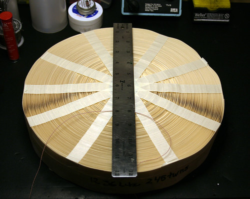
                                This is a 12 stand #36 Litz wire wound pancake coil I made today. It is 245 turn and is 12 inches round. I will test it first by submerging it in dialectic oil. If it tests well then maybe pot it in wax. I have made Tesla coils with Litz wire and have had amazing results using it. I'll update along the build.


                                12 inch Litz Pancake Coil by jiffycoil, on Flickr


                                12- inch Litz Pancake Coil by jiffycoil, on Flickr

                                Comment

                                Working...
                                X