Announcement

Collapse
No announcement yet.

Lockridge Device - Peter Lindemann

Collapse
X
 
  • Filter
  • Time
  • Show
Clear All
new posts

  • Robert49
    replied
    Originally posted by mbrownn View Post
    The number of people that are alive that have seen one of these is very small so any testimony about it is valuable.
    Hi Mbrown.

    Henry also told me that he saw hi-ranked officers fill their gas tanks with water and then put a white disk of some sort. But that's another thing.
    Next time I see him, I'll see if I can get more information from him.

    Robert

    Leave a comment:


  • mbrownn
    replied
    The number of people that are alive that have seen one of these is very small so any testimony about it is valuable.

    Leave a comment:


  • Robert49
    replied
    Originally posted by mbrownn View Post
    Very interesting, could you ask your friend more about it?

    Sorry i did not see this before, I dont have an internet connection at the moment
    Hi.
    Henry was about 10yo then and all he remembers is the device was in an open wooden box , no battery , hand cranked and some kind of swithing sound.

    But I got him interested in free energy about 4 years ago and he is tinkering with different Bedini like motor-generators. He had one 4 coiler that he built and with only one coil on it , he ran it in closed loop for almost 3 hours without a battery and without any capacitor. It probably died because of bearing friction.

    Believe me, if he remembered more he would be working on it himself.

    Good luck.
    Fun to experiment!

    Robert

    Leave a comment:


  • mbrownn
    replied
    Originally posted by Robert49 View Post
    Hi guys.
    I have a german friend who saw one of the original devices working and putting out about 300 watts of electricity.
    He was 10 years old during the war and people had to go underground very deep because of the bombings.
    They used these to light up the place.
    He told me that they hand cranked the device manually and it ran all by itself
    without stopping. He said that he heard a clicking sound when it was working. So KEEP AT IT... It did work !

    Robert
    Very interesting, could you ask your friend more about it?

    Sorry i did not see this before, I dont have an internet connection at the moment

    Leave a comment:


  • mbrownn
    replied
    Originally posted by tachyoncatcher View Post
    I read somewhere that the brushes on the delco/remy unit was ground down thinner for the Lockridge device. Not sure how it helps, but it would be easy to test for someone who has one of these units to try.
    Randy
    I am convinced that the lockridge used a wave wound rotor, if every other segment was disconnected, that would allow for a pulsing circuit provided that the brushes were thinned down so that they could only connect two segments. This means that the brush would only be as wide as one segment. as each brush left the segment, inductive kickback would cause an arc, to prevent this we would need a second set of brushes making contact as the first pair break contact.

    I have tested this and the motor was weak running at only about 15 to 20% efficiency with no collector brushes and 20 to 25% efficiency with them. recovery from the collector brushes was in the 15 to 20% range which would bring us up to 45% efficiency at best on the motor I used. A better motor would do better but you can see that this alone isn't enough and there has to be more going on and there is.

    So the brushes are narrowed to accommodate effective collection of the inductive kickback and to time the pulse.

    There are ways to increase the power and this is part of the problem solved as the efficiency improves a little when we do this but we have to remember the lockridge is a motor generator in the same case, so we don't have any additional generator losses in the iron and the whole generator process is more efficient.

    Introducing transformer actions increases current in the coils and so motor torque, provided we have the geometry right. Now we have a motor, a generator and a transformer all in the same case with only one set of friction and iron losses.

    This gives us a transformer that powers a motor, the transformer isn't great in its efficiency, maybe 60 to 70% but when combined with the generated power it is now doing something special. I cannot give you figures on this at this time because I am still working on the geometry to get the thing working. I don't expect to get my very inefficient motor into overunity but with a more efficient device I am convinced it can be done.

    I have also realized that we do not have to pulse the motor this way but more on that later.

    Although this is a very different device the principals of operation are exactly the same except we are pulsing. Read the text as it tells you how it works but it does not tell you about the geometry. http://www.rexresearch.com/alxandr/3913004.pdf

    Robert Alexander: Dyna-Motor (US Patent # 3,913,004) Overunity, Free Energy

    Leave a comment:


  • tachyoncatcher
    replied
    Brushes

    I read somewhere that the brushes on the delco/remy unit was ground down thinner for the Lockridge device. Not sure how it helps, but it would be easy to test for someone who has one of these units to try.
    Randy

    Leave a comment:


  • Robert49
    replied
    Originally posted by mbrownn View Post
    Yes, there is at least one group working on this which I am a part of. We are running tests on a motor that will not be self running but are learning what we need to do to make a self runner. After we have gained enough knowledge to understand, we will be posting here but there is little point in posting something that is not going to work as it will lead people up the wrong path. If anything is found that is new or additional to what I have already posted I will update you.
    Hi guys.
    I have a german friend who saw one of the original devices working and putting out about 300 watts of electricity.
    He was 10 years old during the war and people had to go underground very deep because of the bombings.
    They used these to light up the place.
    He told me that they hand cranked the device and it ran all by itself
    without stopping. He said that he heard a clicking sound when it was working. So KEEP AT IT... It did work !

    Robert
    Last edited by Robert49; 08-13-2012, 11:59 AM. Reason: spelling

    Leave a comment:


  • wantomake
    replied
    Still trying!!

    thanks mbrown,

    I've spent hundreds of hours trying to get the PM motor to work. Had small successes, and learned a lot. Heat build up, arching, the different winding configurations. But all of this was a good learning time and fun, but with many let downs.
    I do have a 1954 chevy delco generator (rebuilt) and will switch all my energy to it.
    On a personal note, I do believe there is a way to do this. With all that we need there is hope in this project.
    james

    Leave a comment:


  • tekmann
    replied
    DC motors running on negative energy

    Hi All,

    Have watched Peters DVD several times over and now understand what I have been exposed to for years. The Back EMF or negative enrgy force within DC motors when running. So this got me thinking about picking off the the back EMF to build or attempt to build the lockridge devise.

    So while contemplating this I thought about what wouild happen when you run a DC motor on Negative energy such as a negatively charged battery. Is the Back EMF still there? Does it exist as another form of Back EMF to counter act the driving negative energy force running the DC motor?

    Bud

    Leave a comment:


  • mbrownn
    replied
    A very misunderstood motor.

    A very misunderstood motor.

    I haven't posted for a while so I thought I would put a little light upon what I am doing.

    The Universal motor is usually described as simple and similar to a permanent magnet motor and while in appearance it does look simple I can assure you is not.

    The two field coils do operate in the same way as permanent magnets but there is much more going on. There are many interactions going on between the two field coils and also the rotor coils and they are transformer like in nature especially on AC and Pulsed DC. In the standard setup which is known as a series wound conductive compensation setup, any inductive effects between the two field coils are cancelled by the transformer action. This has the effect of reducing arcing at the commutator increasing its life and reducing heat in the armature. A similar effect can also be achieved on an AC current when the second field coil is disconnected from the series wound setup and shorted upon itself. This is known as inductive compensation and the action is a transformer action.

    These transformer actions are setup to reduce reactance in the armature.

    Along with these transformer actions we do have back electro motive force (BEMF) occurring in all three of the coils. This BEMF can be setup so that the transformer action opposes it, or works in the same direction. When it is working in the same direction we get reduced speed, torque and increased arcing as well as much more heat produced. Part of the problem of heat build up is because the armature is in effect one big loop of coils on an iron core (a multi cored shorted transformer). To take advantage of this unison of power we need to change the configuration of the armature and add a second path for the energy to dissipate.

    Note that reducing reactive power us usually the opposite of what a free energy researcher wants to do and that combining the transformer functions of a universal motor could be very important when it comes to building a lockridge device (not so subtle hint)

    Leave a comment:


  • mbrownn
    replied
    Originally posted by wantomake View Post
    My first post ever . I've been following this thread since the beginning and have tested several different motor/gens. Is there any more interest in this? I've learned so much from this, would be great to finish this device.
    Thanks,
    wantomake
    Yes, there is at least one group working on this which I am a part of. We are running tests on a motor that will not be self running but are learning what we need to do to make a self runner. After we have gained enough knowledge to understand, we will be posting here but there is little point in posting something that is not going to work as it will lead people up the wrong path. If anything is found that is new or additional to what I have already posted I will update you.

    Leave a comment:


  • wantomake
    replied
    My first post ever . I've been following this thread since the beginning and have tested several different motor/gens. Is there any more interest in this? I've learned so much from this, would be great to finish this device.
    Thanks,
    wantomake

    Leave a comment:


  • joeqsmith
    replied
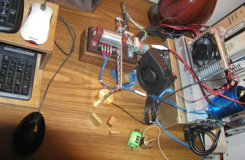
    A few videos of the dynamometer. It now uses ceramic bearings and a brushless absorber. When used with the balance, it yeilds some very impressive results measuring motors well into the few Watt range.

    I have ran tests as high as 25,000 RPM at up to 80 Watts with it.

    minidyno.wmv - YouTube

    minidyno cal - YouTube

    Mini-Dynamometer - YouTube

    Leave a comment:


  • joeqsmith
    replied
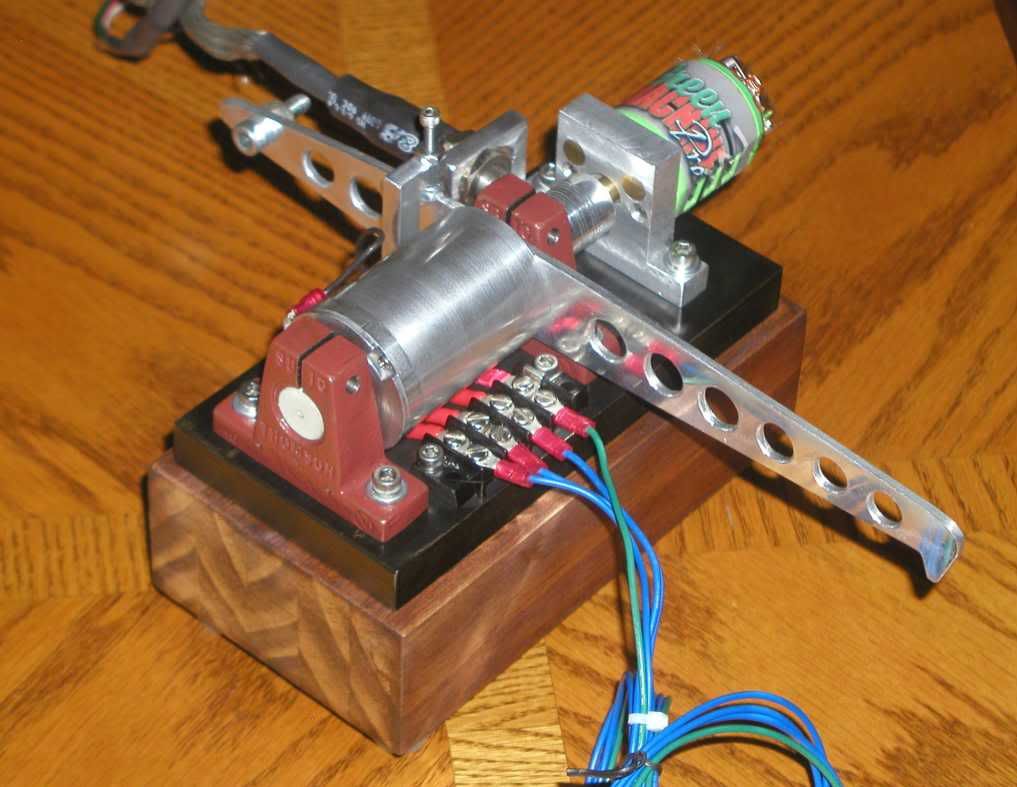
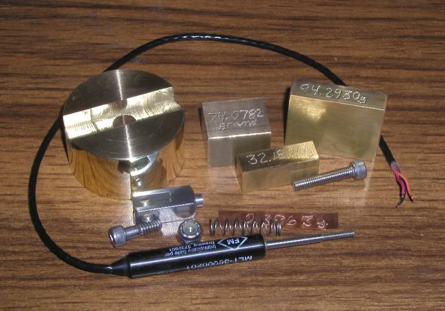
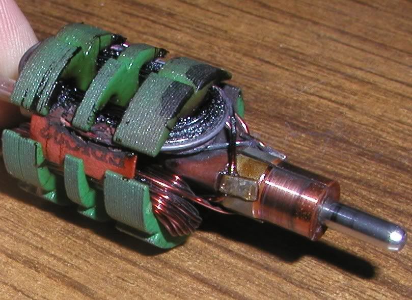
    [IMG][/IMG]


    Leave a comment:


  • mbrownn
    replied
    for the kind words,

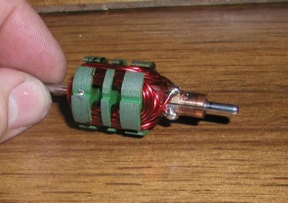
    I am totally convinced that this is how the original device worked, it is different from what we have seen in that I have modified the armature but if the original had the wave wound armature there would be no need for modification although I believe having a modified rotor, like I have done, will work a little better. The main difference is I have blank segments between the coils.

    Other than building it, what needs to be done? optimize the geometry and optimize the windings. I think I am that close. Once I know this for sure I will start to release how to do it with other motors. It is so simple that I find it hard to believe that it took me so long to get there but you would not understand that it could work without understanding what all the parts do and how they interact. The device is simple but the interactions are complex.

    I think I could wire an SG to do it so when the time comes I will start a thread on that as this is a simple pulse motor that most of us understand but I am getting ahead of myself. I have to prove it first.

    The peg motor works in a totally different way and produces a different energy, hence Johns interest. I will watch with interest but wont participate much until I have this thing sorted.

    The three battery system could be used to improve a Lockridge COP, hence my interest but you would need to match the motor to the batteries and we don't know how to produce the bad battery yet.

    Get ready to replicate guys, especially if I can do it with a universal motor.

    Leave a comment:

Working...
X