Announcement

Collapse
No announcement yet.

Lockridge Device - Peter Lindemann

Collapse
X
 
  • Filter
  • Time
  • Show
Clear All
new posts

  • Dragon is Right.

    Bugler,

    Dragon is right. Learn the little steps (lessons) first. The larger, more powerful designs will grow from these.

    Peter
    Peter Lindemann, D.Sc.

    Open System Thermodynamics Perpetual Motion Reality Electric Motor Secrets
    Battery Secrets Magnet Secrets Tesla's Radiant Energy Real Rain Making
    Bedini SG: The Complete Handbook Series Magnetic Energy Secrets

    Comment


    • Hi Peter,
      I have watched the DVD and it looks straight forward. But I have a question. Seems that everyone seeks a way to get rid of the generator function in a typical DC motor. Usually this generator effect is produced in the rotor windings as they move through a magnetic field thus creating BEMF and reducing input current. But what about the attraction motors? They don't have any field magnets or field coils, just stator electromagnets and a rotor made out of silicon steel that turns as it is attracted by the stator poles. So there are no two magnetic fields that are interacting and inducing BEMF. Am I right? So why isn't such a motor OU even without capturing the back spike? And how can I make my motors better based on the info on the dvd? I doubt that pulsing my motor coils once or twice per revolution with a HV cap will improve anything, but I can be wrong. I would appreciate your comment on this.
      Thanks,
      Jetijs
      It's better to wear off by working than to rust by doing nothing.

      Comment


      • Good Questions

        Originally posted by Jetijs View Post
        Hi Peter,
        I have watched the DVD and it looks straight forward. But I have a question. Seems that everyone seeks a way to get rid of the generator function in a typical DC motor. Usually this generator effect is produced in the rotor windings as they move through a magnetic field thus creating BEMF and reducing input current. But what about the attraction motors? They don't have any field magnets or field coils, just stator electromagnets and a rotor made out of silicon steel that turns as it is attracted by the stator poles. So there are no two magnetic fields that are interacting and inducing BEMF. Am I right? So why isn't such a motor OU even without capturing the back spike? And how can I make my motors better based on the info on the dvd? I doubt that pulsing my motor coils once or twice per revolution with a HV cap will improve anything, but I can be wrong. I would appreciate your comment on this.
        Thanks,
        Jetijs
        Jetijs,

        As usual, you are right on the money. However, I am going to postpone answering these questions until I have posted what I promised on Friday. The main part of the answer is that the attraction motors are "special" designs that require a machine shop to build, whereas the motor modifications I am taking about now require less tooling and skill.

        Peter
        Peter Lindemann, D.Sc.

        Open System Thermodynamics Perpetual Motion Reality Electric Motor Secrets
        Battery Secrets Magnet Secrets Tesla's Radiant Energy Real Rain Making
        Bedini SG: The Complete Handbook Series Magnetic Energy Secrets

        Comment


        • Operations of a Commutated DC Motor

          Hi Folks,

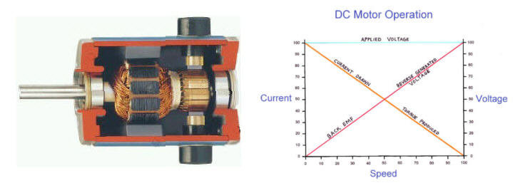
          OK, here is the next installment. Below is an image of a DC motor and the chart of its operational characteristic.


          For the sake of simplicity, we will discuss this with regard to a DC motor with a permanent magnet field, like the one shown in the drawing. Assuming nice round numbers, let us postulate that this motor will rotate at 2000 rpm on a 12 volt input with no load. So, we can see that the maximum POWER point is where the lines cross on the graph, when the motor is turning at 1000 rpm. Here, it generates 6 volts of Back EMF. Everyone who has seen my DVD should understand this pretty well.

          Implied, but not said specifically in the DVD, is the following.

          As we saw in the regenerative motor, the electrical energy should only be used to produce a magnetic field and then be recovered. So, what happens in the ordinary DC motor? Believe it or not, the same thing!

          The problem is that the applied voltage that produces the magnetic field in the rotor is first reduced by half (at the power peak) by the Back EMF, and then when that magnetic field discharges (because the brushes move to the next commutator section) the electrical energy produced has nowhere to go except be SHORT CIRCUITED within the rest of the rotor windings.

          So, the ordinary DC motor operates like a regenerative motor, except that ALL of the applied electricity that could be recovered is lost inside the machine. The first half of this energy is destroyed by the Back EMF, and the second half is shorted out in the machine.

          Think about this very carefully. Take your time and think it through. The modifications to the motor to fix this situation are next.

          Peter
          Last edited by Peter Lindemann; 01-09-2011, 10:48 PM.
          Peter Lindemann, D.Sc.

          Open System Thermodynamics Perpetual Motion Reality Electric Motor Secrets
          Battery Secrets Magnet Secrets Tesla's Radiant Energy Real Rain Making
          Bedini SG: The Complete Handbook Series Magnetic Energy Secrets

          Comment


          • DC Motor Modifications to Produce Regenerative Behavior

            Hi folks,

            OK. Sorry I don't have any diagrams to illustrate this. You will just have to picture it in your own mind from this description.

            So, as I stated in the last post, there are two ways the electrical energy is lost in the motor, so there are going to be two, primary parts to the fix.

            The first thing we are going to do is remove the rotor from the motor and remove all of the windings in all of the slots except ONE SET. So, for instance, if the rotor has 20 slots, then we will only leave wire wound through slots #1 and #11 and terminating on their corresponding commutator sections.

            This modification will allow the motor to operate as a "pulse motor", producing TWO torque pulses per revolution of the shaft.

            The problem with this, is that when the brushes move off of the commutator segments connected by this winding, the magnetic field will discharge and ARCH BACK to the brushes, burning the commutator up in short order.

            The fix for this is to ADD a second set of brushes that engage the commutator exactly ONE COMMUTATOR SEGMENT width away from the main, power brushes. This second set of brushes will engage the commutator segments connected to the rotor winding exactly at the point when the power brushes disengage. So, now the magnetic field may discharge its stored energy back out of the motor through the second set of brushes. We will discuss where to send this electrical recovery impulse shortly.

            The final issue is to bias the Back EMF downward on the graph shown in the previous post. To do this, we have to run the motor on a higher voltage than it was originally designed to do. So, for instance, if the motor was originally designed to run at 2000 rpm on 12 volts (as in the example above), then if we run it on 36 volts at 1000 rpm, we know it will produce 6 volts of Back EMF at that point. So, this is equivalent to running it in a position where 5/6ths of the voltage and current are getting through the motor. This suggests that we should be able to recover up to 3/4ths of our applied electricity on our secondary brushes without interfering with our torque production.

            So, to summarize this example, we take a permanent magnet DC motor designed to run at 2000 rpm (in an unloaded condition) on 12 volts DC. We remove all of the windings on the rotor except ONE SET, and we add a second set of brushes to capture the collapsing field went the first set of brushes disengages. Then, we run this motor from a 36 volt battery bank and send the recovered energy to a second 36 volt battery bank, through a power diode to prevent reverse currents (like in a Bedini SSG circuit).

            So, this is the very simplified set of modifications to turn a standard DC motor into a pulsed, high torque, regenerative motor. Add a flywheel to average the torque, and load the system to 1000 rpm and you are "good to go". This is the FIRST STEP in learning to build a "self running" machine, based on these principles.

            None of these modifications should require a machine shop.

            I hope this explanation is clear enough, and that you understand what I am trying to accomplish with these modifications.

            Peter
            Last edited by Peter Lindemann; 01-09-2011, 11:41 PM.
            Peter Lindemann, D.Sc.

            Open System Thermodynamics Perpetual Motion Reality Electric Motor Secrets
            Battery Secrets Magnet Secrets Tesla's Radiant Energy Real Rain Making
            Bedini SG: The Complete Handbook Series Magnetic Energy Secrets

            Comment


            • Peter,
              First of all. Thank You for what you shared with us at the conference, and for continuing it here. As I understand it, the second set of brushes are connected through a diode directly to the second 36 volt battery bank, with no other circuitry.

              As for the circuit providing power to the motor, is there a need for a commutator so that a constant voltage is not applied? You make no mention of this in the third part but a commutator is included in your description in part one.
              “Advances are made by answering questions. Discoveries are made by questioning answers.”
              —Bernhard Haisch, Astrophysicist

              Comment


              • Hi

                I think this is what Peter means. Peter if I'm wrong please pm me and I will change as required.

                Regards
                John
                Attached Files
                Last edited by john_g; 01-12-2011, 09:32 AM. Reason: Diagram removed as incorrect

                Comment


                • Questions:

                  Wont power be transfered from the primary battery to the charging battery when the comutator is bridging both brushes at the same time?

                  Is this any different then a Newman motor other than the magnets and the coils are trading places? Except the problem that I stated in the first question which is easily solved with the Newman arangement.

                  Comment


                  • john_g,
                    Peter said only two slots out of twenty on the commutator would be wound, from what I understand, and you have eleven sections shown on that commutator with about half of them represented as "wound" which I think is far too many. Increased number of sections, with fewer wound would be a more accurate representation. At least from what I understand.
                    “Advances are made by answering questions. Discoveries are made by questioning answers.”
                    —Bernhard Haisch, Astrophysicist

                    Comment


                    • Hey John Q

                      I think if we put the diode on the other recovery brush and run it to the positive of the charging battery it would work without transfering power from the primary.

                      Comment


                      • Originally posted by Mark View Post
                        Questions:

                        Wont power be transfered from the primary battery to the charging battery when the comutator is bridging both brushes at the same time?

                        Is this any different then a Newman motor other than the magnets and the coils are trading places? Except the problem that I stated in the first question which is easily solved with the Newman arangement.
                        I thought that the brushes were filed down on the original lockridge device so
                        that would not occur.

                        FRC

                        Comment


                        • If the charge battery is at or above the source battery voltage it can not pass through the diode. If the charge battery is at a lower voltage than the souce it will be pulse charged by the source and BEMF until the voltage levels out and exceeds the source.

                          It really wouldn't matter that the brushes were overlapped at that point, as long as there is a connection to the recovery brush at exit. At the moment the power brush is disconnected it offers a path for the BEMF through the recovery brush. Instead of a huge arc you get a controlled recovery path.

                          If you take it one step farther, remove all the existing windings and rewind it so each coil is separated or isolated from each other with the same 4 brush commutator then you have a continuous run, continuous BEMF recovery... add a couple more brushes and...... you also have a generator output.
                          ________
                          GLASS SMOKING PIPES
                          Last edited by dragon; 05-11-2011, 11:15 AM.

                          Comment


                          • Not Quite

                            Originally posted by dragon View Post
                            If the charge battery is at or above the source battery voltage it can not pass through the diode. If the charge battery is at a lower voltage than the souce it will be pulse charged by the source and BEMF until the voltage levels out and exceeds the source.

                            It really wouldn't matter that the brushes were overlapped at that point, as long as there is a connection to the recovery brush at exit. At the moment the power brush is disconnected it offers a path for the BEMF through the recovery brush. Instead of a huge arc you get a controlled recovery path.

                            If you take it one step farther, remove all the existing windings and rewind it so each coil is separated or isolated from each other with the same 4 brush commutator then you have a continuous run, continuous BEMF recovery... add a couple more brushes and...... you also have a generator output.
                            Dragon,

                            You're thinking is generally correct, but in this specific case, you are not. I ran the experiment you recommend over 8 years ago and the output from the secondary set of brushes is very small. The reason is, as long as the power brushes can charge up the next set of windings, the magnetic field of the rotor cannot change very much to produce an output in the winding connected to the secondary set of brushes.

                            This is why I said to take the other windings OFF, so the power input becomes a PULSED event, with discrete ON and OFF operations. This allows for a much bigger recovery and OUTPUT.

                            John G,

                            Your drawing is not correct. The brushes can only cover one segment of the commutator at a time, and the recovery brush is exactly ONE COMMUTATOR segment away from the power brush, so it engages at the exact moment the power brush disengages.

                            Peter
                            Peter Lindemann, D.Sc.

                            Open System Thermodynamics Perpetual Motion Reality Electric Motor Secrets
                            Battery Secrets Magnet Secrets Tesla's Radiant Energy Real Rain Making
                            Bedini SG: The Complete Handbook Series Magnetic Energy Secrets

                            Comment


                            • Interesting. So the way a normal starter armature is wound would just cutting the connections be sufficient? Or do the wires actually need to be removed?

                              Comment


                              • Originally posted by Peter Lindemann View Post
                                Dragon,

                                You're thinking is generally correct, but in this specific case, you are not. I ran the experiment you recommend over 8 years ago and the output from the secondary set of brushes is very small. The reason is, as long as the power brushes can charge up the next set of windings, the magnetic field of the rotor cannot change very much to produce an output in the winding connected to the secondary set of brushes.

                                This is why I said to take the other windings OFF, so the power input becomes a PULSED event, with discrete ON and OFF operations. This allows for a much bigger recovery and OUTPUT.

                                John G,

                                Your drawing is not correct. The brushes can only cover one segment of the commutator at a time, and the recovery brush is exactly ONE COMMUTATOR segment away from the power brush, so it engages at the exact moment the power brush disengages.

                                Peter
                                I understand, that makes complete sense. I didn't consider the next coil in line as to what it was doing to the core. Thanks Peter, it helps when someone points out the obvious. ( forest and trees thing ).
                                ________
                                Zoloft settlement info
                                Last edited by dragon; 05-11-2011, 11:15 AM.

                                Comment

                                Working...
                                X