Announcement

Collapse
No announcement yet.

Lockridge Device - Peter Lindemann

Collapse
X
 
  • Filter
  • Time
  • Show
Clear All
new posts

  • Speed continued

    Somehow I could not get this in last post with edit.
    page 12-14 summary

    Quote
    However, by increasing velocity v for linear generator or angle speed ω for rotor, the magnetic drag force F wouldn’t be increased at all and the voltage e would be increased. This way, the generator can still deliver the same output power but with less drag. The less drag means less input mechanical force G for the same output power. That way the generator could have over unity behavior.

    Refer to pdf's in last post

    FRC

    Comment


    • Brush Placement

      Originally posted by n84dafun View Post
      Mark,

      I should have waited longer before getting this. I thought it was going to be like Matt's. It was very difficult to get all the wires out because of the glue as you mentioned, but I finally got it out. Now I have to figure out how to do the zig zag winding. Here are some of the before and after pictures:

      ImageShack Album - 6 images

      I tried the method of just cutting the wires on the commutators and leaving the 4 commutators uncut, but that didn't work (it wouldn't spin).

      Brian
      Brian,

      Nice pictures. Thanks for sharing. I'm curious though, why have you placed the brushes like this:


      instead of how I suggested in Post #263? (repeated here)


      How do you think this is going to work? It doesn't look like you will have enough space in-between the power brushes to have the recovery brushes one commutator space away.

      Peter
      Last edited by Peter Lindemann; 01-16-2011, 05:31 PM.
      Peter Lindemann, D.Sc.

      Open System Thermodynamics Perpetual Motion Reality Electric Motor Secrets
      Battery Secrets Magnet Secrets Tesla's Radiant Energy Real Rain Making
      Bedini SG: The Complete Handbook Series Magnetic Energy Secrets

      Comment


      • Peter,

        I placed the brushes this way because initially I thought I could just cut the wires connecting to the commutators and not have to do any rewinding, but that didn't work, and also because the fact that the magnets are arranged N-S-N-S and the pos neg brush pairs were at 90 degrees. I would have arranged the brushes the way you drew it had I known I had to rewire the rotor like I have to do now.

        If you have time, could you draw a diagram of how to rewire the rotor in the zig zag pattern, and the corresponding connections with the brushes? I'm thinking I should start at one commutator, wind a length of wire CW around 4 adjacent poles, skip one pole, then wind CCW around the next group of 4 adjacent poles, then repeat that pattern again for a total of 4 windings going around the rotor to correspond with the NSNS arrangement of the stator magnets, and finally terminating at a commutator 90 degrees from the start commutator. Hope that made sense, I could draw my diagram, if you want.

        Brian

        Originally posted by Peter Lindemann View Post
        Brian,

        Nice pictures. Thanks for sharing. I'm curious though, why have you placed the brushes like this:


        instead of how I suggested in Post #263? (repeated here)


        How do you think this is going to work? It doesn't look like you will have enough space in-between the power brushes to have the recovery brushes one commutator space away.

        Peter

        Comment


        • Originally posted by Mark View Post
          Good Work n84dafun!

          How did you get the insulators and wires out? I finally just gave up and ordered the motor Matt has. I'm still going to see if I can just buy some blank rotors, if I can I'll order 4 of them.

          Did you remove the whole commutator board from the cover? Is that glued in too? Or did you just have to drill the top of the 4 studs down to remove it, assume that you did remove it.

          Can I mail you my rotor so you can remove my winding? I'll give you $5.00.

          Mark
          I don't think I would even do it for $50! I almost broke skin a few times with the screw driver and pliers trying to rip, twist, and tear all the wires out, and all during that time I was swearing and cussing.

          To get the brush mount board out, I had to drill the 4 retaining studs. Then I drilled and tapped 3 places to remount back into place after modding the board.

          brian

          Comment


          • Originally posted by n84dafun View Post
            I don't think I would even do it for $50! I almost broke skin a few times with the screw driver and pliers trying to rip, twist, and tear all the wires out, and all during that time I was swearing and cussing.

            To get the brush mount board out, I had to drill the 4 retaining studs. Then I drilled and tapped 3 places to remount back into place after modding the board.

            brian
            $50.00! Man your ripping me off I've wondered which way will work better for winding also, the zig zag method or the method you described above. Thats why I'm hopeing I can buy a few blank rotors so I can test it.

            The zig zag method is really easy to wind but hard to describe. If you look back a few posts Peter descibed how to do it and then a few posts after that I made some comments to clarify it.

            Here's another desciption. Hold the rotor out in front of you so you can spin it between your fingers. Now if your were to take a piece a wire and weave in between the slots to make and "S". Actually 2 "S"'s stacked on top of each other. Once you go around 1 time you keep following the same pattern so the wires lay on top of each other. The wires wont criss cross each other they will lay on top of each other and follow the same pattern. Starting from the commutator side lay the wire thru slot #1 then go past 4 slots and and lay it thru slot #5 going back toward the commutator. (this is for 16 slot rotor) Then continue past the next 4 slots and lay the wire thru slot #9 away from the commutator, go past 4 slots and lay the wire thru slot #13 toward the commutator again. Go 4 slots down and lay the wire thru slots #1 again and you'll be laying the wire over the begining of you first wrap. Then just continue winding over and over following the same pattern.

            Hope that makes sense. After you get it all wound put it in a box and mail it to me!!

            Mark

            Comment


            • Wiring Diagram

              Brian,

              I have explained this wiring method numerous times.

              Just to clarify, here is another description.

              Starting at the commutator side, lay your wire into slot #1. Coming out of Slot #1, lay the wire along the back edge of the rotor until you get to slot #5. Then enter slot #5 and come back to the commutator side again. Then go over to slot #9 and lay the wire down slot #9 and come out on the back side again. Then go over to slot #13 and come back over to the commutator side. Then, on to slot #1 again.... around in that pattern until the slots are filled. This is for a 16 slot rotor. The ends of the wires will terminate on two commutator segments that are 180* away from each other when the wire in the slots are sitting in the middle of the stator poles.


              I am not good at three dimensional drawing, so here is an END VIEW of the motor from the commutator end.


              Hopefully, you and everyone else can understand this. The commutator section is just arriving at the brush when the windings are in the middle of the magnetic fields. The windings on the back side of the rotor cross from #1 to #5 and from #9 to #13, assuming a 16 slot rotor.

              I hope this clears this up, once and for all.

              Peter
              Peter Lindemann, D.Sc.

              Open System Thermodynamics Perpetual Motion Reality Electric Motor Secrets
              Battery Secrets Magnet Secrets Tesla's Radiant Energy Real Rain Making
              Bedini SG: The Complete Handbook Series Magnetic Energy Secrets

              Comment


              • Mark and Peter,

                Thank you for your descriptions and illustration! 
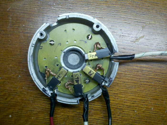
I can clearly see how to wind and connect the system now. What an unusual way to wrap a rotor! Doesn't seem like it would create much magnetic flux compared to wrapping individual poles, but it does simplify the wrapping process.

                Brian

                Comment


                • I looked read back to Peter's previos post:

                  "Mark, YES, the zig-zag winding is exactly what I am saying. Try it, you'll like it! This allows repulsion off of all 4 magnets in the stator. We are not trying to wind the rotor to create "poles" in the classical sense. All we want to do is put current carrying conductors in front of the stator poles, to produce the 90* off thrust vector, with the least Back EMF. Peter Last edited by Peter Lindemann"

                  This answers my question of my last post.

                  Brian

                  Comment


                  • Finally Making Sense

                    Hey Brian,

                    I'm glad it is finally making sense to you. You and Mark have forced me to be very clear about this, which will serve the rest of the readers very well. Thank you.

                    This design is very "counter-intuitive" if you don't know motors like I do. After we fine tune a few of these, the benefits should become obvious.

                    In the end, these motors should have many of the benefits of Bedini's motors, but with really good torque, no electronics, and no machine shop fabrication needed.

                    Thanks for all of your efforts.

                    Peter
                    Peter Lindemann, D.Sc.

                    Open System Thermodynamics Perpetual Motion Reality Electric Motor Secrets
                    Battery Secrets Magnet Secrets Tesla's Radiant Energy Real Rain Making
                    Bedini SG: The Complete Handbook Series Magnetic Energy Secrets

                    Comment


                    • n84dafun,

                      Just wanted to let you know that you inspired me to have a 3rd go of it. I said heck if he can do it so can I. Finally got all the wire off and have rewound my rotor. I used 20awg, looks like it originally might have had 22awg on it to begin with. I'll tackle the commutator tomorrow and see what I have.

                      Another thing I was thinking about is if you hook things up wrong and the rotor just locks up because the polarity is wrong. With a 4 pole set up we can just turn the cover that has the commutator on it 90 degree. With the little gap between the magnets we'll have a little timing to play with also.

                      Mark

                      P.S. Glad we could help Peter

                      Comment


                      • Originally posted by Mark View Post
                        n84dafun,

                        Just wanted to let you know that you inspired me to have a 3rd go of it. I said heck if he can do it so can I. Finally got all the wire off and have rewound my rotor. I used 20awg, looks like it originally might have had 22awg on it to begin with. I'll tackle the commutator tomorrow and see what I have.

                        Another thing I was thinking about is if you hook things up wrong and the rotor just locks up because the polarity is wrong. With a 4 pole set up we can just turn the cover that has the commutator on it 90 degree. With the little gap between the magnets we'll have a little timing to play with also.

                        Mark

                        P.S. Glad we could help Peter
                        Mark,

                        I'm glad you didn't give up on your rotor. It would have been a waste. I think you can just switch the pos with neg power terminal instead. But I agree there is that option to change the timing.

                        Brian

                        Comment


                        • Zig zag

                          Peter Thank you for telling us how to wind our motors zig zag. I did mine that way. My motor is like the one Matt has , I am pulsing mine 4 times per revolution it has good speed and power, and I only have one zig zag coil on it, I am thinking about putting a second coil on it so I can get 8 pulses per revolution. It is running cool with one coil. Do you think to coils and eight pulses per revolution may be to much to get good recovery or is that going to be OK? I have to have to sets of recovery brushes this way so it is a little harder to do. I hope to learn as much as I can. William Reed.
                          Last edited by rosehillworks; 01-17-2011, 02:46 AM.
                          William Reed

                          Comment


                          • Originally posted by rosehillworks View Post
                            Peter Thank you for telling us how to wind our motors zig zag. I did mine that way. My motor is like the one Matt has , I am pulsing mine 4 times per revolution it has good speed and power, and I only have one zig zag coil on it, I am thinking about putting a second coil on it so I can get 8 pulses per revolution. It is running cool with one coil. Do you think to coils and eight pulses per revolution may be to much to get good recovery or is that going to be OK? I have to have to sets of recovery brushes this way so it is a little harder to do. I hope to learn as much as I can. William Reed.
                            William your setup is puzzling to me. (Not that I haven't been puzzled enough already) For you to have 4 pulses per revolution you would need 8 brushes and have 2 repulsion and 2 attraction modes per revolution. And if you filled up the slots when you wound your first coil how you would even be able to wind a second coil. And if you did put 2 coils on you would need 16 brushes.

                            Comment


                            • Mark. My motor has 4 brushes +1 -2 +3 -4 and I have my winding connected to the commutator at brushes 1 and 2 it then goes to 2 and 3 then to 3 and 4 then to 4 and 1 then it starts back at 1 and 2. This is how it has 4 power pulses for every time it goes around. I hope this helps. William
                              William Reed

                              Comment


                              • Recovery System?

                                Originally posted by rosehillworks View Post
                                Mark. My motor has 4 brushes +1 -2 +3 -4 and I have my winding connected to the commutator at brushes 1 and 2 it then goes to 2 and 3 then to 3 and 4 then to 4 and 1 then it starts back at 1 and 2. This is how it has 4 power pulses for every time it goes around. I hope this helps. William
                                William,

                                That is an interesting way to run the motor. It sounds like you don't have a recovery system in place, so you are rapidly frying your commutator. If you don't stop running it, you will cause such deep pitting of the copper it will never be right again. Good luck with your experiments.

                                Peter
                                Peter Lindemann, D.Sc.

                                Open System Thermodynamics Perpetual Motion Reality Electric Motor Secrets
                                Battery Secrets Magnet Secrets Tesla's Radiant Energy Real Rain Making
                                Bedini SG: The Complete Handbook Series Magnetic Energy Secrets

                                Comment

                                Working...
                                X