d'oh
Matt,
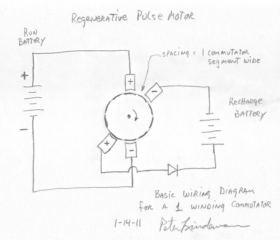
It turns out that the term "zig-zag" has been used two different ways in this thread. The current usage means a kinda side-saddle winding resulting in two coils like you've got. I have only one coil going through exactly two slots. My setup is like the one Peter originally drew - 1 winding commutator.

After mulling it over I do understand this scope trace:

There is no visible spike because it is being smoothed by the attached recharge battery.
The -8v dip in the top trace (connected directly to the recharge brushes) is BEMF / charge. Just like Peter has been telling us. D'oh. It's only 2ms long because that's how long the recharge brushes are in contact with the coil. I'm still running this at +12V, so -8V of BEMF seems about right.
When I add a mechanical load and step up the voltage, I should see the % of this BEMF/charge drop relative to the run voltage.
I'm getting two pulses per revolution, 7ms between pulses * 2 = 14ms per revolution => 71 rps * 60 = 4,286 rpm at 12V with no mechanical load.
Hmmm, , there are 10 pairs of commutations per revolution, hence 10 units of BEMF. 2 units of BEMF are fighting the energization of the coil. 2 units are being pushed into the wrong end of the diode. 6 units of charge build up(?) in the coil (in 3-unit chunks) and do what? Create counter-magnetic fields inside the motor? Does a 3-unit lump of BEMF come spilling out when the run brushes are contacted?
If we added 2 more pairs of brushes (a total of 2 run brushes and 6 recharge brushes), or made the recovery brush 3 commutators wide, we could "drain off" the charge (and do something useful with it?). That sounds too mechanically difficult and too expensive for the goals of this thread...
If I replace the single spike recovery diode with a FWBR, I should be able to capture the spike and send it to the recovery battery plus capture 2 units of BEMF and send that to the recovery battery, also, yes?
pt
Originally posted by Matthew Jones
View Post
It turns out that the term "zig-zag" has been used two different ways in this thread. The current usage means a kinda side-saddle winding resulting in two coils like you've got. I have only one coil going through exactly two slots. My setup is like the one Peter originally drew - 1 winding commutator.

After mulling it over
 I do understand this scope trace:
There is no visible spike because it is being smoothed by the attached recharge battery.
The -8v dip in the top trace (connected directly to the recharge brushes) is BEMF / charge. Just like Peter has been telling us. D'oh. It's only 2ms long because that's how long the recharge brushes are in contact with the coil. I'm still running this at +12V, so -8V of BEMF seems about right.
When I add a mechanical load and step up the voltage, I should see the % of this BEMF/charge drop relative to the run voltage.
I'm getting two pulses per revolution, 7ms between pulses * 2 = 14ms per revolution => 71 rps * 60 = 4,286 rpm at 12V with no mechanical load.
Hmmm,
 , there are 10 pairs of commutations per revolution, hence 10 units of BEMF. 2 units of BEMF are fighting the energization of the coil. 2 units are being pushed into the wrong end of the diode. 6 units of charge build up(?) in the coil (in 3-unit chunks) and do what? Create counter-magnetic fields inside the motor? Does a 3-unit lump of BEMF come spilling out when the run brushes are contacted?
If we added 2 more pairs of brushes (a total of 2 run brushes and 6 recharge brushes), or made the recovery brush 3 commutators wide, we could "drain off" the charge (and do something useful with it?). That sounds too mechanically difficult and too expensive for the goals of this thread...
If I replace the single spike recovery diode with a FWBR, I should be able to capture the spike and send it to the recovery battery plus capture 2 units of BEMF and send that to the recovery battery, also, yes?
pt


Comment