Announcement

Collapse
No announcement yet.

How to turn plastic waste into diesel fuel cheaply

Collapse
X
 
  • Filter
  • Time
  • Show
Clear All
new posts

  • ceramic band heater question

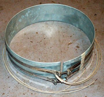
    Has anybody tried using one of these cheap Stainless Steel Electric Band Heater from ebay for their retort?


    Just making concept design. For WMO feedstock only...


    AC 220V 220 Voltage 2300W Ceramic Plug Stainless Band Heater 140mmx180mm | eBay

    I did notice Jetijs used one in an earlier design of his, although it was around 3.8kw from memory.

    Thanks
    Last edited by southoz; 11-11-2013, 12:22 PM. Reason: wrong link

    Comment


    • derek

      Hi guy's,just been contemplating the idea of using halogen lamp principal as a heat source?Instant,quick and same cost as elect elements.What do you think?

      Comment


      • Originally posted by southoz View Post
        Has anybody tried using one of these cheap Stainless Steel Electric Band Heater from ebay for their retort?


        Just making concept design. For WMO feedstock only...


        AC 220V 220 Voltage 2300W Ceramic Plug Stainless Band Heater 140mmx180mm | eBay

        I did notice Jetijs used one in an earlier design of his, although it was around 3.8kw from memory.

        Thanks
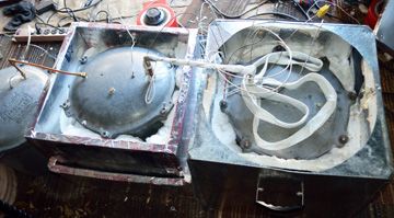
        I use two band heaters on my retort,

        along with a linewrap heater,

        and a hot plate made from a stove heating element.

        They heat my retort fairly rapidly,

        and I control them with PID controllers, and variacs.

        Originally posted by rozier56 View Post
        Hi guy's,just been contemplating the idea of using halogen lamp principal as a heat source?Instant,quick and same cost as elect elements.What do you think?
        Heating a retort with halogen lamps is using radiant heat to heat with. Just as heating a retort with resistance wires that are not in physical contact with the retort is still just radiant heating.

        It is good to keep the laws of thermodynamics in mind when designing a pyrolysis unit. The laws of thermodynamics show that conduction is the most efficient way to heat something. Convection is the next most efficient way to heat something. Radiation is the least effective way to heat something.

        Thus a hot plate, band heaters, and line wrap are the most efficient ways to heat a retort electrically.
        I have been running various blends of waste oils and unleaded gasoline in a 1983 Chevy G-20 van with a 6.2L diesel V-8 engine, with a Stanadyne Rotary DB2 IP since Feb, 2007. I have started the engine with no difficulty and no block heater on an 80/20 (WVO/gas) blend down to 0F (-18c). I have found that by blending as little as 15% gasoline in the summer, and as much as 50% in the winter, my engine starts and runs as if it was running on diesel fuel.

        Comment


        • Praise, suggestions and info ;-)

          Hello guys,
          Well I just read every post and have slowly designed my unit and taken many notes along the way thanks to all your trials and tribulations! Like everyone on this forum I would like to thank the guys who began this topic some years ago. Polymer cracking was rather interesting but as I found waste oil was far easier to get hold of, I soon turned to distillation process of WMO.(for now)

          I have a few questions which perhaps you seasoned vets may be able to answer. While taking notes I have found there to be many differences in cracking and distillation process, temperatures and possible catalysts.

          First of all some information, my proposed unit is an "on the fly" continuous feed process with a goal of producing Diesel fuel.

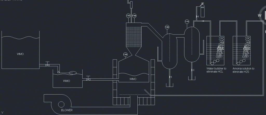
          My plan is to have a rather shallow retort level with large diameter and feed the retort via float traps. This will keep the unit sealed and provide a constant level in my retort/reactor which I can monitor externally by simply looking at my external tank level. My drawing may explain this better. This will be experimental so I won't get upset if it doesn't work.

          The heat source will be LPG at this point until my system is proven, then I will switch to a liquor burner. Everything insulated as required, I have an abundence of insulation and materials at work at which I can acquire to construct my unit. Please keep in mind this is a sketch, not an outright design and not to scale.

          As this is planned to be a continuous feed process I would surmise that once I reach and hold cracking temperature in the retort my plant temperatures, feed rate, condensable and non condensable should remain rather steady. For this reason I am going to try and achieve reflux and condenser temperatures by modifying the distance between them. Thus there will be no reason for axcillary heating or cooling on said equipment. (again this is an experiment)

          So.... My question for you long time buffs that have some knowledge in WMO cracking and distilling is

          1) Optimum Cracker/retort temperature range
          2) Optimum Reflux temperature range
          3) Optimum 1st condenser temperature range to fraction off anything lighter then Diesel

          I will be experimenting with my plant but a temperature goal would be nice to work towards. I've noticed through out the 101 pages the temps have ranged quite a bit so it's hard to get a handle on what top aim for. Keep in mind I want diesel

          Once again, to all the long time forum members that went through hell to get to this point Awesome!

          Last edited by chipsnpips; 11-14-2013, 03:26 AM.

          Comment


          • Nice design, thanks for posting and welcome.

            1) Optimum Cracker/retort temperature range
            I just completed a run of WMO and found I was getting good results up to 405*C. I didn't experiment with any higher temps on this run with this retort. I would say aim at the 400*C mark and tweak from there. Too much temperature will risk boil over while too low is slow. Note also that my retort is tall and skinny so that amongst other things will create variables. Feedstock will have a bearing on the target temps too, for example my current lot has some white spirits mixed in so this boils off early.

            2) Optimum Reflux temperature range
            Ok, I was aiming at 300*C and in doing so I made winter diesel of .83 SG. In other words it was a little on the light side. I'll be aiming at slightly higher temp next time perhaps 320*C. It's early days but I'm going to remove the reflux swarf packing and improve the insulation. There was no catalyst.

            3) Optimum 1st condenser temperature range to fraction off anything lighter then Diesel
            This was talked about only a few weeks ago. I was aiming at 80 -100*C but my set up was struggling to reach the mark. Still the diesel was OK so I'm not sure what to recommend. You could choose a relatively low temp and simply expose the diesel to that temp for a longer duration, which would achieve the same result.

            Hope this helps...
            http://diydiesel.blogspot.co.nz/

            Comment


            • Originally posted by chipsnpips View Post
              Hello guys,
              Well I just read every post and have slowly designed my unit and taken many notes along the way ...
              So.... My question for you long time buffs that have some knowledge in WMO cracking and distilling is

              1) Optimum Cracker/retort temperature range
              2) Optimum Reflux temperature range
              3) Optimum 1st condenser temperature range to fraction off anything lighter then Diesel
              Welcome, chipsnpips, good to know you read through the thread. Nice drawing. I have been working on distilling WMO for about 1.5 years.

              My answers:
              1) Regardless of what hydrocarbon, hydrocarbon cracking temperature is generally considered to be 800F (425c). My last batch of PID controllers were C only and 400c max, but they cracked and evaporated all of my WMO batches.
              2) I keep the retort reflux at cracking temperature (400-425c).
              3) I keep the first condenser at 300c and drop in 100c stages down to 0c.

              On your plan for continuous feed:
              You just want to make sure your flow goes away from your feed and toward your bubbler, and you will be OK.
              I have been running various blends of waste oils and unleaded gasoline in a 1983 Chevy G-20 van with a 6.2L diesel V-8 engine, with a Stanadyne Rotary DB2 IP since Feb, 2007. I have started the engine with no difficulty and no block heater on an 80/20 (WVO/gas) blend down to 0F (-18c). I have found that by blending as little as 15% gasoline in the summer, and as much as 50% in the winter, my engine starts and runs as if it was running on diesel fuel.

              Comment


              • Continous cracking

                Hi chipsnpips, and others

                Great drawing - what are the vertical pipes coming from the base of the condensers? Would a simple non-sprung, steel check valve do the job to ensure the (minimal) pressure and vapours from the retort do not flow back toward the feedstock? Looks like the cups at the bottom of the drain cocks from the condensers are there to provide a liquid seal against air entering the condensers as the fuel automatically drains out? So you're not letting any liquid build up in the condensers, just in the cups? Is the dotted line running down the condensers is a baffle to direct the incoming vapours down through packing on one side and up through more packing on the other side? Do you think this has an advantage over the vapours entering at the bottom of the condensers because the vapours then have to pass through twice as much distance of packing? Perhaps you could get a pocket of light vapours stuck at the entrance point, not condensing downward?

                I am also in the early stages (still) of putting together a continuous, WMO-fed distiller / cracker. My thought for the retort is to use a heavy section of rectangular tube (C-channel with a long lid welded on after initial works are done) on a 20 degree (or so) slope with a gradient of heat ranging from 150C at the high end where the oil drips in, to 450C at the down hill end. The oil runs down the slope until it comes to a temperature hot enough to distil or crack it. I expect there will be a lot of distilling up to 380-425C, and cracking just at the far end of the heat bed. This ensures the lowest amount of heat is used for the shortest period of time (Asad recommended this) to distil each molecule of hydrocarbon, and therefore reduces the chance of degradation. I will pre-treat the feed oil by heating it to and holding at 120C to ensure all the water is removed and also hopefully the light ends with low auto ignition temperatures. Has any one had any advice / experience with auto ignition temperatures being a potential problem at temperatures up to 450-500C? I spoke to a guy who commercially distilled paint thinners and he said to be very careful you do not reach the auto ignition temperature of the feed stock or it will combust even without oxygen present. The square tube will basically be a flat heating bed which I can bracket hot plates to. Each hotplate will have its own thermostat positioned 5mm away from it on the inside of the square tube. I'm thinking of using 5 hotplates to form a steady gradient. I guess I would have to heat the top of the square tube too to prevent vapours condensing on it. Now I think about it I'm not sure a flat bed to bracket hot plates to is better than using band heaters on round pipe (a band heater will heat the floor, ceiling and walls of the round pipe, but a hot plate does one side only).

                Good luck to everyone.
                Col

                Comment


                • Originally posted by Col View Post
                  Hi chipsnpips, and others

                  Great drawing - what are the vertical pipes coming from the base of the condensers? Would a simple non-sprung, steel check valve do the job to ensure the (minimal) pressure and vapours from the retort do not flow back toward the feedstock? Looks like the cups at the bottom of the drain cocks from the condensers are there to provide a liquid seal against air entering the condensers as the fuel automatically drains out? So you're not letting any liquid build up in the condensers, just in the cups? Is the dotted line running down the condensers is a baffle to direct the incoming vapours down through packing on one side and up through more packing on the other side? Do you think this has an advantage over the vapours entering at the bottom of the condensers because the vapours then have to pass through twice as much distance of packing? Perhaps you could get a pocket of light vapours stuck at the entrance point, not condensing downward?

                  I am also in the early stages (still) of putting together a continuous, WMO-fed distiller / cracker. My thought for the retort is to use a heavy section of rectangular tube (C-channel with a long lid welded on after initial works are done) on a 20 degree (or so) slope with a gradient of heat ranging from 150C at the high end where the oil drips in, to 450C at the down hill end. The oil runs down the slope until it comes to a temperature hot enough to distil or crack it. I expect there will be a lot of distilling up to 380-425C, and cracking just at the far end of the heat bed. This ensures the lowest amount of heat is used for the shortest period of time (Asad recommended this) to distil each molecule of hydrocarbon, and therefore reduces the chance of degradation. I will pre-treat the feed oil by heating it to and holding at 120C to ensure all the water is removed and also hopefully the light ends with low auto ignition temperatures. Has any one had any advice / experience with auto ignition temperatures being a potential problem at temperatures up to 450-500C? I spoke to a guy who commercially distilled paint thinners and he said to be very careful you do not reach the auto ignition temperature of the feed stock or it will combust even without oxygen present. The square tube will basically be a flat heating bed which I can bracket hot plates to. Each hotplate will have its own thermostat positioned 5mm away from it on the inside of the square tube. I'm thinking of using 5 hotplates to form a steady gradient. I guess I would have to heat the top of the square tube too to prevent vapours condensing on it. Now I think about it I'm not sure a flat bed to bracket hot plates to is better than using band heaters on round pipe (a band heater will heat the floor, ceiling and walls of the round pipe, but a hot plate does one side only).

                  Good luck to everyone.
                  Col
                  Cheers Excalibur and BB

                  Col,
                  Regarding the fill line, I don't believe a check valve will be necessary as the fluid level will always be maintained above the inlet, thus preventing any vapours returning to the supply tank. The vapours should only rise. The feed line will have minimal flow, the flow should only be equal to what is being sent to the condensers. and this will be matched with an orifice/needle valve once I know what the rate is. I will also be incorporation another float valve into the inlet tank for safety to prevent low levels of WMO.

                  The vertical pipes from the condenser are just drain lines. The little cup your referring too is a standard drawing reference of a tank. I will need to adjust my bleed rate once the process is in full swing to keep the condenser level steady. Keeping a level will ensure the system is enclosed. These valves will just be needle valves.
                  Yes the dotted lines in the condensers are baffles. If the temperatures of the process are correct and the variables are removed from the system then I wouldn't think I'd have a problem with this set up(I hope)

                  Your continuous feed set up sounds interesting, I hope it works for you

                  Thanks for your reply, your comments are well received.

                  Comment


                  • chipsnpips

                    A few constructive thoughts...

                    I made 2 prototypes using the level equilibrium idea. The first was a very small retort and I noticed a reluctance for oil to flow toward the hot zone, almost as if the heat created a kind of pressure barrier. The very small size of piping may have distorted the effect though.
                    The second prototype showed how sensitive the levels were to pressure differences. In your case, the bubbler water height is going to create back pressure. A possible or partial solution could be to reduce the effective bubbler water level to 50mm (2"). Also I speculate that because you are incinerating the non-condensable gases, the second bubbler is unnecessary. I think I'm right in saying that eliminating the 2nd bubbler will halve the back pressure.

                    The non-condensable gas feed to the burner needs a method of diverting gas when/if the volume becomes excessive, otherwise you risk a runaway retort situation. More gas = more heat = more gas = more heat... you get the picture? Think safety! You cannot simply close off the feed dead as there will be major pressure build up. A gas-jar or a way to flare off the surplus could be the answer.

                    Are those level sight glasses on the condensers? If yes, then they need to be vented at their tops, back to the vessel itself. You can't vent to atmosphere otherwise gases or distillate will escape and they won't work without any vent.

                    BTW, what burner head are you planning use? I see you have a blower

                    I'm excited to see how you progress and hoping my ramblings are helpful
                    http://diydiesel.blogspot.co.nz/

                    Comment


                    • Originally posted by chipsnpips View Post

                      The vertical pipes from the condenser are just drain lines.
                      I was referring to the ones on the side of the condensers, not directly off the bottom. You may answer my question in your response to Excalibur's comment.
                      All the best,
                      Col

                      Comment


                      • Originally posted by Excalibur View Post
                        chipsnpips

                        A few constructive thoughts...

                        I made 2 prototypes using the level equilibrium idea. The first was a very small retort and I noticed a reluctance for oil to flow toward the hot zone, almost as if the heat created a kind of pressure barrier. The very small size of piping may have distorted the effect though.
                        The second prototype showed how sensitive the levels were to pressure differences. In your case, the bubbler water height is going to create back pressure. A possible or partial solution could be to reduce the effective bubbler water level to 50mm (2"). Also I speculate that because you are incinerating the non-condensable gases, the second bubbler is unnecessary. I think I'm right in saying that eliminating the 2nd bubbler will halve the back pressure.

                        The non-condensable gas feed to the burner needs a method of diverting gas when/if the volume becomes excessive, otherwise you risk a runaway retort situation. More gas = more heat = more gas = more heat... you get the picture? Think safety! You cannot simply close off the feed dead as there will be major pressure build up. A gas-jar or a way to flare off the surplus could be the answer.

                        Are those level sight glasses on the condensers? If yes, then they need to be vented at their tops, back to the vessel itself. You can't vent to atmosphere otherwise gases or distillate will escape and they won't work without any vent.

                        BTW, what burner head are you planning use? I see you have a blower

                        I'm excited to see how you progress and hoping my ramblings are helpful
                        Rambling's are always helpful to me as most of my thought process is driven this way. ha ha

                        Firstly to answer Col, yea mate the bits on the side are sight glasses. You make a good point, I'll be definitely venting them back to the condenser, I just didn't put to much effort into the sketch. I will eventually be using level switches and a bit of logic with my valving and process control so I don't have to monitor it so often. 1000L might take a while to get through and if I sat there watching it and passing time by drinking beer it would cost me more in beer then just paying for Diesel ha ha ha

                        Now to Excaliburs constructive criticism's,
                        I am curious to see if this equilibrium idea holds up. I would assume the oil would want to almost draw the cooler oil in and I was actually more worried about the opposite effect that you mention.

                        You definitely do have a valid point about the bubbler creating back pressure, don't forget my sketch isn't to scale so I have no idea what size I'm making them/it but I wouldn't have thought a 250mm long dip tube would only produce about 2.5KPa or = to 0.3625 PSI. That's calculated anyway.

                        The second bubbler I thought I may need to keep neighbours happy. I have a bit of property but my neighbours are nice and wouldn't want to up set them so I thought perhaps burning H2S might smell a bit. I have never worked directly with containing such vapours so I was just going off of research ;-)

                        Regarding the gas burn and having the run away boiler. I had an idea with that. I may be wrong so I'll definitely watch it when I'm doing my trials but I had this thought.
                        If the variables are no longer variables then they should stay constant.
                        Assuming this is a continuous process and once your plant is warmed up and operating continuously, temperatures should be maintained and controlled steadily. This should in theory give you an accurate and steady feed rate from your condensers and a steady and accurate flow of gas. Thus after the initial 2 hours or so it may take me to get my plant up to operating temp of 450 deg and running steadily I should be producing a rather steady and consistent flow of gas. Then I can make changes to my primary fuel (LPG) flow to match.

                        The burner I'm using for my trials is just an LPG ring burner. Like a gas stove top but bigger. After I have nailed down the process and can actually produce diesel I'll look into buying a liquor burner/waste oil burner set up. That's why i have a blower in the sketch ;-) but for now it'll just be a gas ring. should work effectively enough for trials. Just a bit expensive to run.

                        Thanks heaps for your suggestions, they are appreciated

                        Comment


                        • I think the basic plan is great and well worth experimenting with and building on. The more we talk and bounce ideas back and forth, the more likely it is that something really good will come up.

                          With regard to the non-condensable gas feed to the burner, the fact that you have a second condenser trap, then bubblers, I think you will probably produce less gas than will create runaway burner heat. I say probably but it's not an absolute given and I'll give you an example. On my previous prototype which I refer to as mk5, I did a run with a 20 liter retort fill. It got to the point of where I thought I'd probably extracted most of the "easy diesel", so I killed the heat. To my surprise the flame continued to burn from non-condensable gases for 38 minutes!!... and it maintained retort heat at approx. 400*C throughout. It would be so good if we could see into the retort and know exactly what is happening. My best guess is that the lower level of liquid meant that more gases were being created as opposed to distillate. The mk5 had 2 condensers in series and a bubbler.
                          With the mk6, at one stage the fresh feedstock was making a large amount of gas within seconds. My servo automatically closed off the feed to the burner which then diverted it to the gas jar. Each time I fed more feedstock, it made more gas than required. The puzzle is why. Possibly it was that the retort level was low and fresh wmo dropped in equals lotsa instant gas. This is where your idea could be a winner. If you can get the wmo feed to work stably....
                          http://diydiesel.blogspot.co.nz/

                          Comment


                          • Auto ignition temperature

                            Sorry guys, I misunderstood this principle. The auto ignition temperature is the minimum temperature at which a vapour will ignite without an external source of ignition in a normal atmosphere / in air. Our application is in the absence of oxygen so this principle may not be applicable to our systems.

                            Col
                            Last edited by Col; 11-19-2013, 06:11 AM.

                            Comment


                            • fabrica de reactores caseros

                              hello friends, while I finish making my reactor I found this website and I think it intersante, I have been in contact with the head in my country and I'm waiting for answers.
                              Greet everyone.

                              Plastic to fuel - Portable Pyrolysis plant

                              Comment


                              • solar panels to use as energy source

                                Hi there. Does anyone uses PV solar panels as a source for electricity heating.

                                I plan to buy 10m2 of PV panels (6 pieces of 240Wp each = 1440W), and I'm trying to estimate how big unit it could power up.

                                According to the original Jetijs device he states that for 60kg unit he uses 6KW.
                                So for me for 1440W=1.44KW will be able to power a 1,4kg unit. According to the simple math. Am I correct ?

                                However I've not deducted other energy losses from inverter etc.

                                Does anyone has some more experience with solar or electrical heating in general ?

                                Thanks

                                Comment

                                Working...
                                X