Announcement

Collapse
No announcement yet.

How to turn plastic waste into diesel fuel cheaply

Collapse
X
 
  • Filter
  • Time
  • Show
Clear All
new posts

  • Beyond Biodiesel
    replied
    Originally posted by Excalibur View Post
    I sorted through the video footage and put together this Orion clip
    Nice video

    Originally posted by Excalibur View Post
    No time to celebrate, already I've given myself a sizeable list of upgrades and improvements. I want the centrifuge running with fuel feed pump plumbed and wired. The gas feed needs another revamp. Sight glass on the diesel reservoir needs replacement. Lengthen and insulate the flue for better draft. Revise the oil feedstock controls. Reflux thermocouple LCD display wired to 12v supply. A dedicated pump and 20m fuel delivery line to the van. So heaps to do.
    Nice upgrades

    Originally posted by Excalibur View Post
    Really, the main problem is keeping the gas feed ignited. The gas can be intermittent plus low pressure so it goes out then suddenly re-ignites with a loud backfire. Mooted was the possibility of using a dedicated LPG torch on minimum, like a pilot flame. Ever notice how a LPG propane torch can go out when put inside a vessel or pipe? I have various gas heater & oven parts.
    Can anyone point to some good information on gas fired equipment?? Thanks.
    The warehouse complex where I am doing my pyrolysis project has an air conditioning and heating business. He has a scrap pile of dead heating units and air conditioners that piles up near the dumpster. I have examined the gas-fired heating units. They all have 2-3 spark plugs in them with a high voltage power supply, and it looks like the spark plugs run continuously. So, you might try that.

    Leave a comment:


  • Excalibur
    replied
    I sorted through the video footage and put together this Orion clip

    No time to celebrate, already I've given myself a sizeable list of upgrades and improvements. I want the centrifuge running with fuel feed pump plumbed and wired. The gas feed needs another revamp. Sight glass on the diesel reservoir needs replacement. Lengthen and insulate the flue for better draft. Revise the oil feedstock controls. Reflux thermocouple LCD display wired to 12v supply. A dedicated pump and 20m fuel delivery line to the van. So heaps to do.

    Really, the main problem is keeping the gas feed ignited. The gas can be intermittent plus low pressure so it goes out then suddenly re-ignites with a loud backfire. Mooted was the possibility of using a dedicated LPG torch on minimum, like a pilot flame. Ever notice how a LPG propane torch can go out when put inside a vessel or pipe? I have various gas heater & oven parts.
    Can anyone point to some good information on gas fired equipment?? Thanks.

    Leave a comment:


  • Beyond Biodiesel
    replied
    Thanks, Excalibur, it is very interesting.

    Leave a comment:


  • Excalibur
    replied


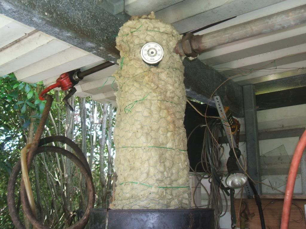
    Pic shows the reflux with what's believed to be rockwool insulation. So far, I like this better than kaowool. The reflux gauge is from a vintage Orion stove which reads in Fahrenheit. The needle points to the word Orion when the diesel is flowing well (approx 700f). I jest, my "stars are in alignment".

    Some more figures and snippets of info:

    The 180 liters made last week used 9 liters of diesel for firing. Keep in mind though that some retort gases are also being burned. At times the retort ran solely on those gases, other times the turk burner head was required to supplement.

    I re-tested the diesel SG after filtering and at ambient temperature of around 20*C. It was .839.

    The centrifuge didn't get completed so I pumped the batch through a strainer, then 5micron bag filter and finally a 1micron bag, all in one pass. The pump used was a 12v Mallory marine gear-pump. I adjusted the relief valve to reduce the flow a bit and give the filters an easier time.

    The centrifuge target is 3840 rpm. According to a centrifuge rpm/diameter chart, the fuel will be subject to 2232g of force. Effectively, this gravity multiplying effect will accelerate the settling process. I plan to use a 12v Facet (aka tick-tick) fuel pump to trickle feed the centrifuge. I'm aiming to strip the fuel clean in one pass but we shall see what's possible.

    I hope this stuff is of interest...?

    Leave a comment:


  • Beyond Biodiesel
    replied
    Originally posted by fox32 View Post
    This is a great info, thank you for taking your time to post it!

    I'we heard that the reflux chambers can be trouble makers so i'l be extra carefull about it, i also found an interesting video on youtube http://images1.okr.ro/auctions.v3/30...61-300_300.jpg and i see that their reflux chamber is at what apperas to be a 45 degress angle, it sounds interesting, i was thinking to replicate their design. Any thoughts on it? (it-s at 6.25).
    It really does not matter what the angle is, or where the retort is; however, in petroleum refining the retort is typically at the bottom of a fractionation column, which extends straight up for several stories.

    Normally, a 5-gallon (20L) retort would be serviced by a 2 story (20foot/6m) fractionation tower; however, for me, and most DIY pyrolysis practitioners, such a high tower poses a serious design problem, so most of us have horizontal fractionation systems. My horizontal fractionation though has gotten too long at roughly 20 feet, so I am planning on stacking it up 4 feet (1m) high and about 8 feet (2m) long.

    Originally posted by fox32 View Post
    Also about the condensers, i have 3 of them, but after hearing about those 7 i'm thinking to add some more. Il put my plans, now they are on the notbeook, so as soon as i finish replicating them in paint i'l post them!

    Thank you and all the best!
    As far as I am concerned the more the merrier; however, I did discover that with my vapor stream rate, a 2ft (1m) water cooled condenser was sufficient. My condensers are staged roughly at 100c intervals from 300c to 0c
    Originally posted by fox32 View Post
    Okay, so i finnaly got to draw it, so i'm gonna also post all the details, not my best paint work, but wil do .
    The drawing looks good. I assume you are insulating all of the heated sections of pipe in between heated condensers.

    Originally posted by fox32 View Post
    So, the reactor is made out of a steel pipe, about 1.5 m long, 20mm thick, with both ends welded, put inside an upside-down 200 l oil drum, with about 20 cm between the walls.
    Sounds good, and I see that you are planning on burning some kind of fuel to heat your retort. It should work fine, but having flames near a pyrolysis unit just scares me too much, so I use electricity to heat mine.

    Originally posted by fox32 View Post
    Through the bottom of the reactor i will have 4 hollow pipes, in a cross section to each side of the reactor, from the bottom of the reactor, exiting at an angle (was thinking 90*) and circulating air from the blower, through the inside of the reactor and between the reactor and the outer drum.
    Much like a log water boiler, only that the pipes won't exit through the top.(not enough room for the lid, exhaust etc).
    I'm thinking that this setup will be more efficient at heating the feedstock from the inside out , but it can also increase tar content the contact area being larger...
    An integrated heat exchanger on the retort sounds good, but troublesome to make.

    Originally posted by fox32 View Post
    All of this insulated with fiberglass.
    Fiberglass insulation is only good to about 100c, so you will need some other kind of insulation. I am not sure what you have access to, but rock wool, or kaowool, or fire bricks are the more common insulators for this temperature. If they are not available to you, then there are effective alternatives. Here is a link to insulation investigations.
    High temperature insulation

    Originally posted by fox32 View Post
    The condensers are 100 l electric water boilers, with their original
    insulation. I'm planning to use them as this and strip them out if necessary.
    The current design isn't final, i'm planning to see how it goes like this, and then maybe switch C2 with cooling tank, and so on.
    I plan to keep the first one at around 200-220c, second at around 150-170 and third cold. As recomended on your forum, btw great link!
    Thanks, for the recommendation of my forum. I believe 200c will be too high for fiberglass insulation. Your retort will need something as well. The steel outer barrel will work fine for insulation. And, maybe that will be all you will want, but you could use less heat if you insulated the outer barrel.

    Originally posted by fox32 View Post
    The wmo burner is still in perfectioning mode, nearly completed it, i went for this design. how to make a EASY waste oil burner - YouTube Still tweaking with it, trying to find the right hole dimension, and air to oil amount. If it won't work good, i think i will try a Turk design or gas burner.

    The reflux chamber i'm thinking to put it at a 45 degrees angle, i saw this on a proffesional rig, an i'm thinking that id made sense, all the heavy stuf flowing back through the botom of the pipe and lighter gases above it.
    The reflux chamber is made from 2 parts, the top one contains the catalists, the bottom one being the refluxer.
    Hope that being that close to the reactor the temperature won't drop much and i wont need to heat it.
    I found if I did not heat my reflux, then the retort would just reflux for hours and never progress.

    Originally posted by fox32 View Post
    I was thinking that the exces gass could be directed to heat the condensers if neded.

    Also, thanks for the over-boiling advice, i'l definetly add some chicken wire or something, didn't knew about this one.

    Now, i'm just waiting for the final parts to arrive, i have about 90% of all parts, the reactor needs some welding,i'm not really sure about those pipes inside, so i'm trying to figure out the best output for this big puzzle!

    Have a great day!
    Chicken wire should work fine for a refluxing medium. Looks good. Keep us posted.
    Last edited by Beyond Biodiesel; 12-20-2013, 07:18 PM.

    Leave a comment:


  • Excalibur
    replied
    Florin

    Thanks for posting, great effort and good plans. You have clearly taken the time to study so have set a good example for others.

    Step by step. That's the way to proceed.

    The reflux may need insulating. I see no problem with the 45* angle. Your three condensers will give you three fuels, tweak temperatures to achieve the required ones. ( I have only 1 condenser so I set temps to maximize diesel production only). Lathe swarf/turnings for the reflux is good. The water cooled condenser will require a water feed supply, else the water will get hot and become less effective.

    Reflux temperature is something that you'll tweak to suit the product required. If you get wax, then decrease.

    The retort will require lots of heat. More than you'd expect. Probably you'll end up fitting a flue pipe ( I speculate).

    Leave a comment:


  • fox32
    replied
    Okay, so i finnaly got to draw it, so i'm gonna also post all the details, not my best paint work, but wil do .

    So, the reactor is made out of a steel pipe, about 1.5 m long, 20mm thick, with both ends welded, put inside an upside-down 200 l oil drum, with about 20 cm between the walls.

    Through the bottom of the reactor i will have 4 hollow pipes, in a cross section to each side of the reactor, from the bottom of the reactor, exiting at an angle (was thinking 90*) and circulating air from the blower, through the inside of the reactor and between the reactor and the outer drum.
    Much like a log water boiler, only that the pipes won't exit through the top.(not enough room for the lid, exhaust etc).
    I'm thinking that this setup will be more efficient at heating the feedstock from the inside out , but it can also increase tar content the contact area being larger...

    All of this insulated with fiberglass.

    The condensers are 100 l electric water boilers, with their original
    insulation. I'm planning to use them as this and strip them out if necessary.
    The current design isn't final, i'm planning to see how it goes like this, and then maybe switch C2 with cooling tank, and so on.
    I plan to keep the first one at around 200-220c, second at around 150-170 and third cold. As recomended on your forum, btw great link!

    The wmo burner is still in perfectioning mode, nearly completed it, i went for this design. how to make a EASY waste oil burner - YouTube Still tweaking with it, trying to find the right hole dimension, and air to oil amount. If it won't work good, i think i will try a Turk design or gas burner.

    The reflux chamber i'm thinking to put it at a 45 degrees angle, i saw this on a proffesional rig, an i'm thinking that id made sense, all the heavy stuf flowing back through the botom of the pipe and lighter gases above it.
    The reflux chamber is made from 2 parts, the top one contains the catalists, the bottom one being the refluxer.
    Hope that being that close to the reactor the temperature won't drop much and i wont need to heat it.

    I was thinking that the exces gass could be directed to heat the condensers if neded.

    Also, thanks for the over-boiling advice, i'l definetly add some chicken wire or something, didn't knew about this one.

    Now, i'm just waiting for the final parts to arrive, i have about 90% of all parts, the reactor needs some welding,i'm not really sure about those pipes inside, so i'm trying to figure out the best output for this big puzzle!

    Have a great day!
    Attached Files

    Leave a comment:


  • fox32
    replied
    This is a great info, thank you for taking your time to post it!

    I'we heard that the reflux chambers can be trouble makers so i'l be extra carefull about it, i also found an interesting video on youtube http://images1.okr.ro/auctions.v3/30...61-300_300.jpg and i see that their reflux chamber is at what apperas to be a 45 degress angle, it sounds interesting, i was thinking to replicate their design. Any thoughts on it? (it-s at 6.25).

    The rope, yeah, it looks the same, only this one is made from asbestos, and yes again, it i too thick for screwing.

    Also about the condensers, i have 3 of them, but after hearing about those 7 i'm thinking to add some more. Il put my plans, now they are on the notbeook, so as soon as i finish replicating them in paint i'l post them!

    Thank you and all the best!

    Leave a comment:


  • Beyond Biodiesel
    replied
    Originally posted by fox32 View Post
    Good day to everybody, and let me tell, you guys, are something rare, doing such an amazing job, and taking the time to teach the rest of us! I'm new to the site, i just found it through the ol' google, searching for plastic to diesel, and for the last day, and past hours i have read until page 54 and now my eyes are like onions and, my neck veins are bulging like Luca Brasi when he-s whacked in Godfather. I have learned a great deal of valuable informatiom, but still i can't seem to figure out some things. So...here it goes.
    Good to know you did your homework.

    Originally posted by fox32 View Post
    1- The reflux chamber. How does it looks on the inside, where does it sits, at what temp(in the early posts jetys recomended a lower temp, at the las page Beyond Bio, recomended top temp) this is my biggest unknown.
    The confusion is there are many ways to skin a cat. So, the reflux chamber needs to be relatively large, so 1/4 the size of the retort, so many of us just partially fill our retort with hydrocarbons to be cracked, then the upper 1/4 of the retort is filled with some highly conductive and high surface material that will not melt. It could be terra cota tiles, wire, metal bug screening, etc. It is intended to avoid boil-over.

    The temperature should be at least the level of your first condenser, so 300-400c. The lower the temperature, and the smaller size, of your reflux chamber, the more likely that you are going to get a plug in it. A plugged reflux chamber means kaboom!

    Originally posted by fox32 View Post
    2- The catalist chamber. It is inside the reflux, after or before?
    Keep in mind that this is backyard DIY cat cracking, so, if this were the petroleum industry, then the feed would be shot through a fluidized bed of catalyst, then pass through the reflux chamber.

    However, to simplify the design for the DIY, then the catalyst chamber could be combined with the reflux. Or the catalyst could be just inside the retort boiling with the hydrocarbons.

    Originally posted by fox32 View Post
    3- Should the first condenser be before the cooling tank or after it?
    You cannot hope to get a reasonable extraction from the fluid stream with just one condenser. Most of us have staged condensers. I have 7 stages before the bubbler. Each condenser is after the trap (cooling tank) that collects the fraction.

    Originally posted by fox32 View Post
    4- would grapitated azbest rope/simple azbest rope be a good substituent for a seal? Maybe for replacing teflon tape in threads?
    I am not sure what grapitated azbest rope is, nor is Google. My guess is you are talking about graphite cordage, or rope. It is too porous to use as a seal, however, there are seals made of graphite that work excellently as seals. However, I do not believe any of it is thin enough to function as a pipe thread seal. The best is just to use stainless steal tapered thread fittings and tighten them until the seal is leak tight, for any fitting that operates above 350c, otherwise teflon tape works great.

    Originally posted by fox32 View Post
    And last one, Beyond Biodiesel, and Excalibur, from what i have read you have some nice setups, also Jetys but he wasn't on the forum for a while -you may have done this already- but could you post some schematics, plans, photos, anything that can be a source of inspiration on the forum? That will be highly apreciated!
    Both of us have posted boat-loads of photos here, and both of us have links to blogs, or forum threads, with our photos on them. Here is a link to a section of a forum that I run that has my (and others) pyrolysis work organized by topic.
    Pyrolysis of Hydrocarbons

    Originally posted by fox32 View Post
    Thanks alot guys, i wish you a Merry Christmas and all the best!

    Florin

    Edit* Forgot to mention, i'm only using plastic, and i want to get as much diesel as possible.
    Welcome, Florin, and keep us posted on your developments.
    Last edited by Beyond Biodiesel; 12-19-2013, 02:28 PM.

    Leave a comment:


  • fox32
    replied
    Greetings guys, merry christmas!

    Good day to everybody, and let me tell, you guys, are something rare, doing such an amazing job, and taking the time to teach the rest of us! I'm new to the site, i just found it through the ol' google, searching for plastic to diesel, and for the last day, and past hours i have read until page 54 and now my eyes are like onions and, my neck veins are bulging like Luca Brasi when he-s whacked in Godfather. I have learned a great deal of valuable informatiom, but still i can't seem to figure out some things. So...here it goes.

    1- The reflux chamber. How does it looks on the inside, where does it sits, at what temp(in the early posts jetys recomended a lower temp, at the las page Beyond Bio, recomended top temp) this is my biggest unknown.

    2- The catalist chamber. It is inside the reflux, after or before?

    3- Should the first condenser be before the cooling tank or after it?

    4- would grapitated azbest rope/simple azbest rope be a good substituent for a seal? Maybe for replacing teflon tape in threads?

    And last one, Beyond Biodiesel, and Excalibur, from what i have read you have some nice setups, also Jetys but he wasn't on the forum for a while -you may have done this already- but could you post some schematics, plans, photos, anything that can be a source of inspiration on the forum? That will be highly apreciated!


    Thanks alot guys, i wish you a Merry Christmas and all the best!

    Florin

    Edit* Forgot to mention, i'm only using plastic, and i want to get as much diesel as possible.
    Last edited by fox32; 12-19-2013, 08:25 AM.

    Leave a comment:


  • Beyond Biodiesel
    replied
    Safe journey rozier56.

    Leave a comment:


  • rozier56
    replied
    Merry Christmas

    Merry to all,and a happy new year.I am off to the U.K. to see my grandson for the first time,leaving hot south Africa,Capetown,30*c for London 3*c.Thanks to all for this great project this year and will see you in the new year.
    Regards,Derek

    Leave a comment:


  • Excalibur
    replied
    Thanks.

    According to Chevron, specific gravity for no.2 diesel at 15.6°C, is between 0.88 and 0.82.

    Am working on the centrifuge as I urgently need it running. More updates later, including an idea for a retort level indicator.

    Leave a comment:


  • Beyond Biodiesel
    replied
    Good work Excalibur, your diesel SG is spot on, because the engineering tool box says:
    Diesel Fuel Oil 2D/3D/4D/5D (60F) (15.6 c) 0.81 - 0.96sg
    Liquids and Fluids - Specific Gravities - SG

    For flow control you might look into a metering pump, or metering valve to control the input of raw material.

    Leave a comment:


  • Excalibur
    replied
    I tested the specific gravity at 837gr for a liter. Someone correct me but isn't this on the light side? I can't find my chart of SG ratings. Can someone post a good link with a chart of all the diesel SG. Here the season is going into summer and it looks like it's going to be a hot one.

    The fuel color is the same as previous batches. It's dark green with any quantity like when a jar fill is viewed. It's transparent red if light is shined through and it's amber in small amounts like that of a (8mm) 5/16" polyethylene hose. Otherwise it looks clean and bright, though previous experience says it will have particles less than what the eye can physically see.

    This run I insulated the diesel reservoir, however it caused the temperature to exceed my 80 -100*C target which in turn caused the sight level indicator hose to deteriorate. Interestingly enough, the diesel reservoir is at 42*C 17hrs after the heat was turned off. I'd really like to get the centrifuge sorted and running before all that heat leeches away. I don't see that happening this time...

    The counter-current preheating of the ingoing feedstock has got me excited. I think I'm onto something good with this idea. As is so often the case, there's problems to resolve and one of the more difficult ones is precisely controlling the feed flow. I need to know how many liters per hour and use that as a point of reference. My set up has a crude system of valves but the control is rather sensitive.

    The revised turk burner head showed some good signs but the gas feed is proving a pain. There is backfiring if conditions aren't exactly right which isn't what you need when you trying to distill a large vessel of hydrocarbon. For the last 3 or 4 hours I elected to simply flare off the gas with a vintage Bunsen burner. I rued not having a kettle ready ... all that clean burning flame going to waste!

    More pics and updates on the blog shortly. Maybe even a video if they turn out any good.

    Leave a comment:

Working...
X