Announcement

Collapse
No announcement yet.

How to turn plastic waste into diesel fuel cheaply

Collapse
X
 
  • Filter
  • Time
  • Show
Clear All
new posts

  • It looks like you have struck gold first time with your clay catalyst. Many types of clay will work but you are lucky to have found a good one first time.
    Typically a clay catalyst will take a bit of time to get working, hence the dark coloured fuel at first, then lovely yellow fuel follows. If your catalyst is like mine it will produce good yellow fuel for two more batches and then stop working, producing fuel that darKens and thickens.
    How did you prepare your clay? What size of pieces? What colour? How much did you use?

    Its a good idea to figure out how much of your fuel is gasoline/kerosene/diesel.
    weigh a sample of the fuel, heat it to 90 degreesC and keep it at that temp for about half an hour to boil off the gasoline. Weigh it again. heat it to 170 C for another half hour to boil off the kerosene and weigh it again. Its best to do this on an electric hotplate rather than over a gas flame as the vapours are highly inflammable.
    My fuel is 60% diesel 30%kerosene and 5% petrol/gasoline. The other 5% is gas and char. Yours may be quite different.

    Comment


    • Originally posted by unaiz View Post
      thanks alot i have read almost 21 pages hope to get on 48th soon but still i have few questions & some ideas that may be could make the process better

      what did you use as reflux my frnd?

      & u don't know how happy i am after knowing that i give small amount of char .. i was worried about it & about the efficiency of this device i am thinking to do a test run in a pot or pressure cooker could it be feasible ?

      i will post soon the whole idea i have thought for this test run & really looking forward for your advice and ideas for that
      The read is a fascinating one that takes time & effort. Keep it up. The last read-through took me a week!

      I will help of course but please be mindful that I am learning too. Not all my ideas will end up being correct and naturally opinions vary.

      For the reflux I used old red clay planter pots, broken into small pieces. I'm still puzzled as to what temperature I should be aiming for with this reflux. Various posts on the forum suggest temps between 150 and 270. Logically I reason, it should be tied to the outcome that is wanted. My set up requires much work to maintain and stabilize any chosen target temperature.

      Re: the char. I've inspected the residue from my first run only, not from the second run as yet. Your test run could be in a pot but should not have rubber seal/s. The temps are way too hot for that. Also note that aluminum has a melting point of 660'C. Please take a minute to consider safety. Don't overfill the pot with feedstock and use decent size plumbing, nothing pathetically small as an 8mm tube! There's a post from an Indian man with an old paint tin which expanded "like a balloon". The tube blocked and pressurized the vessel!
      http://diydiesel.blogspot.co.nz/

      Comment


      • Originally posted by imakebiodiesel View Post
        It looks like you have struck gold first time with your clay catalyst. Many types of clay will work but you are lucky to have found a good one first time.
        Typically a clay catalyst will take a bit of time to get working, hence the dark coloured fuel at first, then lovely yellow fuel follows. If your catalyst is like mine it will produce good yellow fuel for two more batches and then stop working, producing fuel that darKens and thickens.
        How did you prepare your clay? What size of pieces? What colour? How much did you use?

        Its a good idea to figure out how much of your fuel is gasoline/kerosene/diesel.
        weigh a sample of the fuel, heat it to 90 degreesC and keep it at that temp for about half an hour to boil off the gasoline. Weigh it again. heat it to 170 C for another half hour to boil off the kerosene and weigh it again. Its best to do this on an electric hotplate rather than over a gas flame as the vapours are highly inflammable.
        My fuel is 60% diesel 30%kerosene and 5% petrol/gasoline. The other 5% is gas and char. Yours may be quite different.
        Thanks. Clay from old red planter pots were broken into small pieces, the max size was 20mm. The reflux had just under half full of clay.
        The reactor and reflux had some big swings in temperature, so I was wondering if this was contributing to colour variation. I remind that the feedstock was mostly clean mineral oil, perhaps 90% with 10% PE
        http://diydiesel.blogspot.co.nz/

        Comment


        • Excalibur

          Originally posted by Excalibur View Post
          The read is a fascinating one that takes time & effort. Keep it up. The last read-through took me a week!

          I will help of course but please be mindful that I am learning too. Not all my ideas will end up being correct and naturally opinions vary.

          For the reflux I used old red clay planter pots, broken into small pieces. I'm still puzzled as to what temperature I should be aiming for with this reflux. Various posts on the forum suggest temps between 150 and 270. Logically I reason, it should be tied to the outcome that is wanted. My set up requires much work to maintain and stabilize any chosen target temperature.

          Re: the char. I've inspected the residue from my first run only, not from the second run as yet. Your test run could be in a pot but should not have rubber seal/s. The temps are way too hot for that. Also note that aluminum has a melting point of 660'C. Please take a minute to consider safety. Don't overfill the pot with feedstock and use decent size plumbing, nothing pathetically small as an 8mm tube! There's a post from an Indian man with an old paint tin which expanded "like a balloon". The tube blocked and pressurized the vessel!
          oh thanks for the info ..i was bit extra conscious about safety as well thats one of the reason for delaying in my test run can i get your mail id so i could mail you or chat you there

          Comment


          • Originally posted by Excalibur View Post
            The read is a fascinating one that takes time & effort. Keep it up. The last read-through took me a week!

            I will help of course but please be mindful that I am learning too. Not all my ideas will end up being correct and naturally opinions vary.

            For the reflux I used old red clay planter pots, broken into small pieces. I'm still puzzled as to what temperature I should be aiming for with this reflux. Various posts on the forum suggest temps between 150 and 270. Logically I reason, it should be tied to the outcome that is wanted. My set up requires much work to maintain and stabilize any chosen target temperature.

            Re: the char. I've inspected the residue from my first run only, not from the second run as yet. Your test run could be in a pot but should not have rubber seal/s. The temps are way too hot for that. Also note that aluminum has a melting point of 660'C. Please take a minute to consider safety. Don't overfill the pot with feedstock and use decent size plumbing, nothing pathetically small as an 8mm tube! There's a post from an Indian man with an old paint tin which expanded "like a balloon". The tube blocked and pressurized the vessel!
            oh & yeah i can understand that you are in the process of learning too but we both could help each other where its required .. how much did ur setup costs you ? ummm yeah are you using some catalyst ?? what did you actually use?

            Comment


            • I have used broken terracotta as a catalyst and got good results from it. Its difficult to be exact about the temp of the reflux column. Remember that it is doing two jobs.
              reflux column. The crucial temperature is the very top of the column. If you hold this temp at say 200c then any vapour that condenses above 200c will form a liquid and trickle back down into the reactor to be cracked again. The selected temperature will affect the eventual fuel mix.
              catalyst column, in this role the temperature of the clay pieces are important. each catalyst has a different critical temp, too high and it will coke quickly, too low and it just wont work.
              It really is a matter of try it and see. Also its very important to keep notes of the results. After you have done 20 or 30 experimental "burns" its very difficult to remember the early results.

              Comment


              • Originally posted by imakebiodiesel View Post
                I have used broken terracotta as a catalyst and got good results from it. Its difficult to be exact about the temp of the reflux column. Remember that it is doing two jobs.
                reflux column. The crucial temperature is the very top of the column. If you hold this temp at say 200c then any vapour that condenses above 200c will form a liquid and trickle back down into the reactor to be cracked again. The selected temperature will affect the eventual fuel mix.
                catalyst column, in this role the temperature of the clay pieces are important. each catalyst has a different critical temp, too high and it will coke quickly, too low and it just wont work.
                It really is a matter of try it and see. Also its very important to keep notes of the results. After you have done 20 or 30 experimental "burns" its very difficult to remember the early results.
                did the catalyst you add need to be filter at the end of process? , are you sure catalyst won't react with any thing inside &
                did the purity of fuel obtained becomes less with the addition of catalyst ?

                Comment


                • I have read about 1/3 through this thread. It is a most interesting project, which I am planning on working on. I just have a few suggestions for now.

                  1) You folks really need to be purging your retorts with an inert gas, such as nitrogen or CO2 throughout the heating process, or kaboom!! There goes you and half your neighborhood.

                  2) Why reinvent the wheel. There is a very excellent flange system already in place for this temperature range. It is called a Conflat Flange.
                  I have been running various blends of waste oils and unleaded gasoline in a 1983 Chevy G-20 van with a 6.2L diesel V-8 engine, with a Stanadyne Rotary DB2 IP since Feb, 2007. I have started the engine with no difficulty and no block heater on an 80/20 (WVO/gas) blend down to 0F (-18c). I have found that by blending as little as 15% gasoline in the summer, and as much as 50% in the winter, my engine starts and runs as if it was running on diesel fuel.

                  Comment


                  • The next stage following experiment 3 with the temp test rig

                    I propose the following changes and upgrades based on what was learnt from experiment #3 using the temporary test rig, pictured in post 1424

                    The reactor vessel will be swapped out for approx 50liter LPG style cylinder. A top flange will be added. Piping to the reflux and continuos feed reservoir will enter directly below the flange. Rockwool style of lagging will wrap around the outer drum. A diesel blower, possibly using fuel injector nozzles at 40psi will supply heat. Digital temp controller to switch injectors and fan on/off.

                    Reflux: The plan is a long cylindrical steel 4" tube, mounted vertically above the reactor with an internal perforated grate to support the catalyst. Depending on whether the reflux requires heating or cooling, hot flue gases may be piped over the reflux vessel which will have vertical fins, encased in a cowling. Cool air would substitute should the reflux need cooling. Top and bottom hatches, with the grate attached to the lower hatch so it comes out with it .

                    Condenser #1: Air cooled with vertical fins using forced air from a fan. Hope to find some kind of thermostat for the 150'C ( I think it is?) Perhaps a digital controller for here too.

                    Condenser #2: Water cooled jacket with a water heater style thermostat triggering a solenoid which opens a water valve. (I think this is 80'C?)

                    Condenser #3 As above but with temperature set low to 20'C

                    Bubbler: Hope to find a clear vessel which will also capture uncondensable gases and route those as reactor heat.

                    Comments please.
                    Thanks for viewing

                    unaiz
                    how much did ur setup costs you ?
                    Well umm those orange vessels for the reflux and condensers cost.. $2 each!
                    The thermocouple cost $33... Add a bit of oxy/acetylene $? The rest I had or was otherwise free. So, the set up as you see it in post 1424 cost around $50
                    Note: this test rig was only for testing purposes.

                    ummm yeah are you using some catalyst ?? what did you actually use?
                    Best re-read the posts from 1424 onward. Reflux catalyst is explained there in some detail.
                    Last edited by Excalibur; 06-05-2012, 04:45 AM.
                    http://diydiesel.blogspot.co.nz/

                    Comment


                    • Flanges

                      Originally posted by Beyond Biodiesel View Post
                      I have read about 1/3 through this thread. It is a most interesting project, which I am planning on working on. I just have a few suggestions for now.

                      1) You folks really need to be purging your retorts with an inert gas, such as nitrogen or CO2 throughout the heating process, or kaboom!! There goes you and half your neighborhood.

                      2) Why reinvent the wheel. There is a very excellent flange system already in place for this temperature range. It is called a Conflat Flange.
                      It is good information about the flanges. No need to reinvent the wheel

                      Comment


                      • Originally posted by Excalibur View Post
                        I propose the following changes and upgrades based on what was learnt from experiment #3 using the temporary test rig, pictured in post 1424

                        The reactor vessel will be swapped out for approx 50liter LPG style cylinder. A top flange will be added. Piping to the reflux and continuos feed reservoir will enter directly below the flange. Rockwool style of lagging will wrap around the outer drum. A diesel blower, possibly using fuel injector nozzles at 40psi will supply heat. Digital temp controller to switch injectors and fan on/off.

                        Reflux: The plan is a long cylindrical steel 4" tube, mounted vertically above the reactor with an internal perforated grate to support the catalyst. Depending on whether the reflux requires heating or cooling, hot flue gases may be piped over the reflux vessel which will have vertical fins, encased in a cowling. Cool air would substitute should the reflux need cooling. Top and bottom hatches, with the grate attached to the lower hatch so it comes out with it .

                        Condenser #1: Air cooled with vertical fins using forced air from a fan. Hope to find some kind of thermostat for the 150'C ( I think it is?) Perhaps a digital controller for here too.

                        Condenser #2: Water cooled jacket with a water heater style thermostat triggering a solenoid which opens a water valve. (I think this is 80'C?)

                        Condenser #3 As above but with temperature set low to 20'C

                        Bubbler: Hope to find a clear vessel which will also capture uncondensable gases and route those as reactor heat.

                        Comments please.
                        Thanks for viewing

                        unaiz

                        Well umm those orange vessels for the reflux and condensers cost.. $2 each!
                        The thermocouple cost $33... Add a bit of oxy/acetylene $? The rest I had or was otherwise free. So, the set up as you see it in post 1424 cost around $50
                        Note: this test rig was only for testing purposes.


                        Best re-read the posts from 1424 onward. Reflux catalyst is explained there in some detail.


                        any idea of using some alternative for thermo couples & i was asking did the catalyst effect the purity of final fuel ? & its effects in process

                        Comment


                        • Originally posted by Excalibur View Post
                          I propose the following changes and upgrades based on what was learnt from experiment #3 using the temporary test rig, pictured in post 1424

                          The reactor vessel will be swapped out for approx 50liter LPG style cylinder. A top flange will be added. Piping to the reflux and continuos feed reservoir will enter directly below the flange. Rockwool style of lagging will wrap around the outer drum. A diesel blower, possibly using fuel injector nozzles at 40psi will supply heat. Digital temp controller to switch injectors and fan on/off.

                          Reflux: The plan is a long cylindrical steel 4" tube, mounted vertically above the reactor with an internal perforated grate to support the catalyst. Depending on whether the reflux requires heating or cooling, hot flue gases may be piped over the reflux vessel which will have vertical fins, encased in a cowling. Cool air would substitute should the reflux need cooling. Top and bottom hatches, with the grate attached to the lower hatch so it comes out with it .

                          Condenser #1: Air cooled with vertical fins using forced air from a fan. Hope to find some kind of thermostat for the 150'C ( I think it is?) Perhaps a digital controller for here too.

                          Condenser #2: Water cooled jacket with a water heater style thermostat triggering a solenoid which opens a water valve. (I think this is 80'C?)

                          Condenser #3 As above but with temperature set low to 20'C

                          Bubbler: Hope to find a clear vessel which will also capture uncondensable gases and route those as reactor heat.

                          Comments please.
                          Thanks for viewing

                          unaiz

                          Well umm those orange vessels for the reflux and condensers cost.. $2 each!
                          The thermocouple cost $33... Add a bit of oxy/acetylene $? The rest I had or was otherwise free. So, the set up as you see it in post 1424 cost around $50
                          Note: this test rig was only for testing purposes.


                          Best re-read the posts from 1424 onward. Reflux catalyst is explained there in some detail.

                          & do insulate your reflux condensers & reactors bro it will make your process quiet efficient

                          Comment


                          • The conflat range of flanges is meant for single use only. The metal sealing ring would have to be replaced every time you filled the reactor.
                            Excluding oxygen is important both for safety and fuel yield but in a batch system once the initial air in the reactor headspace has been purged either by steam or by the first few minutes of cracking no further air can enter the reactor. Even if the reactor had a leak the pressure inside the vessel is higher than the outside so vapours will leak out rather than air getting in.
                            In a continuous feed reactor the air can enter with fresh feedstock so continuous purging is necessary.
                            Most catalysts are in the form of lumps or pellets. This way the gases can make their way through the catalyst freely and at the same time come in close contact with the catalyst surface. The catalyst does not, or at least should not, react with the gases. It improves or accelerates the cracking process ensuring the final product is a liquid not a wax.

                            Comment


                            • Originally posted by imakebiodiesel View Post
                              Excluding oxygen is important both for safety and fuel yield but in a batch system once the initial air in the reactor headspace has been purged either by steam or by the first few minutes of cracking no further air can enter the reactor. Even if the reactor had a leak the pressure inside the vessel is higher than the outside so vapours will leak out rather than air getting in.
                              In a continuous feed reactor the air can enter with fresh feedstock so continuous purging is necessary.
                              I agree, I think oxygen gets expelled early on in the heating process. The bubbler gives a slight amount of back pressure, denying air the opportunity to enter. In any case it would seem that the air/fuel ratio would be far from ideal combustion, much like over-rich mixture in a gasoline engine. I'm not a chemist but I know a motor will not fire unless the mixture is within a tight range. That said, we need to be very mindful of what we're dealing with.
                              The continuous feed allowing air into the reactor has me thinking. Plastic would need to be melted to remove the air gaps between the granules, at least. However oil feedstock could be gravity feed from overhead assuming the pipeline was purged to begin with. A third possibilty could be oil with a plastic granules content. My thoughts earlier was to heat the oil to 100'C to drive off any water content before feeding the hot reactor. Any water content might be meet with unwanted reaction!
                              http://diydiesel.blogspot.co.nz/

                              Comment


                              • Originally posted by Excalibur View Post
                                I propose the following changes and upgrades based on what was learnt from experiment #3 using the temporary test rig, pictured in post 1424

                                The reactor vessel will be swapped out for approx 50liter LPG style cylinder. A top flange will be added. Piping to the reflux and continuos feed reservoir will enter directly below the flange. Rockwool style of lagging will wrap around the outer drum. A diesel blower, possibly using fuel injector nozzles at 40psi will supply heat. Digital temp controller to switch injectors and fan on/off.

                                Reflux: The plan is a long cylindrical steel 4" tube, mounted vertically above the reactor with an internal perforated grate to support the catalyst. Depending on whether the reflux requires heating or cooling, hot flue gases may be piped over the reflux vessel which will have vertical fins, encased in a cowling. Cool air would substitute should the reflux need cooling. Top and bottom hatches, with the grate attached to the lower hatch so it comes out with it .
                                An LPG tank or compressor tank is a good idea for a retort (reaction vessel); however, a scrap yard might turn up a 50-100L tank with conflat flanges already installed.

                                Rockwool style insulation is good insulation, but the retort only needs to go to 300c (575F). So, there is no reason to go over the top and build, or buy, a kiln, when you do not need one. I am using a hot plate a pressure cooker and R-Max insulation and getting to 400F (200c) with no problem. I expect to get to 300c (575F) in a few days with only a few minor modification.


                                Originally posted by Excalibur View Post
                                Condenser #1: Air cooled with vertical fins using forced air from a fan. Hope to find some kind of thermostat for the 150'C ( I think it is?) Perhaps a digital controller for here too.
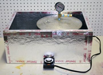
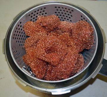
                                I have the first two condensers. The first is just another pressure cooker with no heat sink. It works fine. I installed copper wool column packing in it. It works great to trap the middle fractions.

                                Originally posted by Excalibur View Post
                                Condenser #2: Water cooled jacket with a water heater style thermostat triggering a solenoid which opens a water valve. (I think this is 80'C?)
                                I made a 6 foot (2 meeter) water jacketed condenser with twisted aluminum flashing for the column packing. It works great to trap the diesel fraction.

                                Originally posted by Excalibur View Post
                                Condenser #3 As above but with temperature set low to 20'C
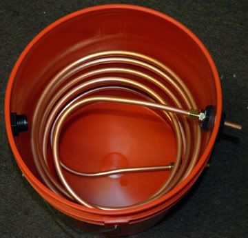
                                I made a 20 foot (6 meter) copper coil in a bucket for the final condenser. It will have ice in it to trap everything from gasoline (petrol) down.

                                Originally posted by Excalibur View Post
                                Bubbler: Hope to find a clear vessel which will also capture uncondensable gases and route those as reactor heat.

                                Comments please.
                                Thanks for viewing
                                Dump the bubbler. It is useless.
                                Originally posted by imakebiodiesel View Post
                                The conflat range of flanges is meant for single use only. The metal sealing ring would have to be replaced every time you filled the reactor.
                                Correct, but it goes to 450c (842F). On the other hand, PTFE (teflon) is good to 500F (260c), so I am going to replace the rubber seals in my pressure cooker with handmade PTFE seals to see if I can get away with it. It means I can reuse the seals.
                                Originally posted by imakebiodiesel View Post
                                Excluding oxygen is important both for safety and fuel yield but in a batch system once the initial air in the reactor headspace has been purged either by steam or by the first few minutes of cracking no further air can enter the reactor. Even if the reactor had a leak the pressure inside the vessel is higher than the outside so vapours will leak out rather than air getting in.
                                In a continuous feed reactor the air can enter with fresh feedstock so continuous purging is necessary.
                                I wouldn't bet my life, house and kids on it.
                                Originally posted by imakebiodiesel View Post
                                Most catalysts are in the form of lumps or pellets. This way the gases can make their way through the catalyst freely and at the same time come in close contact with the catalyst surface. The catalyst does not, or at least should not, react with the gases. It improves or accelerates the cracking process ensuring the final product is a liquid not a wax.
                                Dump the catalyst it is an unnecessary complication. If you use catalyst you will have to figure out how to regenerate it. Whereas, thermal cracking is working just fine for backyard cracking of plastics into diesel fuel.
                                Last edited by Beyond Biodiesel; 06-05-2012, 01:27 PM.
                                I have been running various blends of waste oils and unleaded gasoline in a 1983 Chevy G-20 van with a 6.2L diesel V-8 engine, with a Stanadyne Rotary DB2 IP since Feb, 2007. I have started the engine with no difficulty and no block heater on an 80/20 (WVO/gas) blend down to 0F (-18c). I have found that by blending as little as 15% gasoline in the summer, and as much as 50% in the winter, my engine starts and runs as if it was running on diesel fuel.

                                Comment

                                Working...
                                X