Announcement

Collapse
No announcement yet.

Joule Ringer!

Collapse
X
 
  • Filter
  • Time
  • Show
Clear All
new posts

  • @BrOnsOn77 - Interesting heat issue. It seems to me, that the resistance of the Primary may not be high enough...but is just a guess. When building traditional Tesla towers, the Primary is the area that can greatly affect amp draw. A normal small Slayer Exciter type of tower system will use a Primary of a couple of turns of wire (whereas Lasersaber uses a full amount of turns as his). If you increase the number of turns, the amp draw will go down, but the output will go down too. Decrease and the amps go up, yet the output might not change much. That's the balancing act to be played with such systems.
    So, I wonder if your thicker gauge wiring is where the large amp draw is coming from. Being as it's a toroid and not a straight piece of ferrite, the recirculating energies might be playing a part ? I'm sure others will know more than I, but just a thought.
    I've destroyed plenty of MOSFET's doing something similar with 12V non controlled amperage. They fizz and hiss and then go 'plink' as they hit the floor of the plastic kitchen bin !
    I was saying earlier about the draw being only what the circuit will need. Thing is, if there is no restriction to that flow of current, it won't put a stop on the current. hence this thing about looking at the Primary winding for resistance. A resistor on the Collector output might be a route, to simulate extra turns.

    @All -
    With various folks talking about the ferrite tubes found around cabling, I wound one up for this SJR 3.0 circuit.
    We know the SJR 3.0 will light a variety of bulbs...how about crossing that to charging different types of batteries ?
    Well, it looks like it blasts dendrites, rejuvenates busted cells and the extra bonus is that it does so in just a few seconds !
    I fully expect the few seconds effect to be a gateway for charging regularly, but, as shown in the video, 2x dead alkalines charged in a few seconds to return to running a kitchen temperature meter !
    This build also features a handy 'ON' indicator, which also shows coil loadings by the brightness of the LED. It's a wireless energy pickup, made from a coil from a floppy drive motor assembly and an LED soldered to its wires. If the circuit isn't outputting HV, the LED won't come on, so it makes a great circuit checker.

    Here's the video:
    Super Turbo Battery Charger - YouTube

    Pic of the circuit:

    Comment


    • Mag SJR 3.0 V1 031012

      [IMG=http://imageshack.us/a/img254/9133/dsc05467vd.jpg][/IMG]

      Uploaded with ImageShack.us

      Using crt toroid 100 t 30 awg 800 t 26 awg 12.50 v dc
      load 1st strip 1.2 amp with 2 strips 1.10 amps with 3 strips 1.09 amps
      with magnets on the toroid 0.89 amps the 30 leds using av on the center tap

      totoalas
      Last edited by totoalas; 10-03-2012, 10:38 AM.

      Comment


      • Supercap...

        @ slyder2732
        Hi,
        Do you try to charge a supercap with it?

        Comment


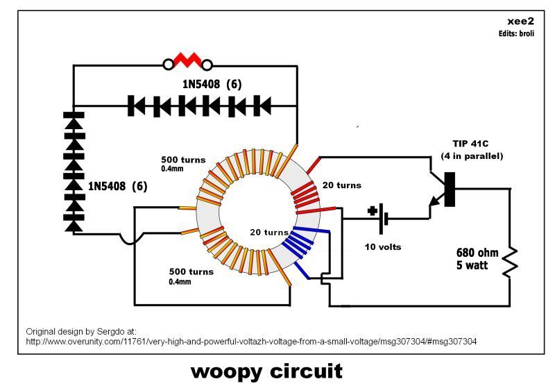
        • @ bronson77 here's an experiment Woopy did using a toroid and self oscillating transistor a few months back, may help in your endeavor

          @ Slider well done as usual, nice work

          dave

          almost forgot the pic
          Half of the Answer is knowing the right Question

          Comment


          • Cheers chaps, hoping it furthers uses for these.

            @Totoalas, interesting and good output there...i've had something similar work with litz type wire, taken off the neck of the monitor. Wound both sides though on that one. Easy enough to wind when in 2 halves. The guys with the similar setup working as a team some while ago showed paper/card in between the halves. I wonder if output would be even better ?

            @Wistiti - Welcome to the forum, hadn't seen your previous posts
            Just tried what you suggested.
            1F 5V Supercap (very old but it's still trucking along)
            11V from cordless drill pack.
            5 seconds saw it rise to 5V, so I stopped and it fell back to sit at 1.5V
            5 seconds more saw it rise to 5.15V, fell back to 2.10V
            Good confirmation that a real charge is going on

            Comment


            • Thanks for all the feedback gang! Certainly gives me some options to try.

              So I tested the circuit out with an 18v cordless drill battery and it did light the 7.5w LED, but it made the transistor very hot. I'm thinking maybe more windings on the primary will help resist some of those amps in the battery. I noticed in Lasersaber's videos that he isn't using batteries that have lots of current.

              Would running the collector to ground help cool the transistor?

              Comment


              • Good progress then BrOnsOn
                You could always parallel connect more transistors of the same type, if you have them, to spread the load. Just a temporary fix, while the amp issues are present, but would save degradations from overheating.

                Lasersaber is in fact using very high output batteries, but he's not likely straining them due to the single 3055 used.. His 14V will be a 4S lipo, of around 500mAh by the looks of it. Discharge can be a few amps for short perods. In R/C applications, such a battery pack (if not self made from 4 cells) would go in something like a lap racing car, where space would be limited inside but high performance required. Normal runnings are of about 6 or 7 minutes at 'flat out'.
                The only real way to get 14V in such a size is with 4x lipo's of 3.7V, giving 14.8V, but up to 16.8V fully charged.

                Comment


                • Thanks for the reply Slider - I saw your battery charging idea and I just tried that myself. It did indeed charge the dead alkaline battery. Have you done any prolonged tests to see how long the battery will last?

                  I just tried charging an AA battery (initial voltage was .93v) using the circuit and it charged up to a sitting voltage of 1.04v. That was only sitting on the charger for maybe 10 seconds. The transistor got VERY hot again lol. That's a pretty cool idea.

                  So is the LED in your video burning on an electrostatic field?

                  Comment


                  • Slider and All:
                    I added more turns to the secondary of my 3 inch rod, by adding another layer of winds on top of the first layer. The small transistor was replaced with the MJE 3055. I also added a couple of diodes as Slider suggested to the base. It does run cooler now, but on 12v it still gets hot after a while.
                    Some very interesting things do happen when placing the diodes on the base circuit, things that I can't explain. But, I got shocked bad that I threw the diodes across the room, and I'm still looking for them. Ha!
                    I also added an earth ground to the base.
                    As I'm still working on it... more later.

                    I think that until we make the exact replication of the 3.0, it just ain't gonna work the same. Heat is the main issue, so heat sinks are in order.
                    Why LS doesn't need them is my question.
                    Perhaps if he would give us a hand... we might get there a bit quicker
                    Last edited by Nick_Z; 10-03-2012, 08:13 PM.

                    Comment


                    • Thanks for the confirmation. I like projects like this, there's no BS alert when other people do the very same thing.
                      Haven't done any prolonged tests...not had any prolonging time yet !

                      The 1F Supercap idea though was a winner from Wistiti, who's name I have to carefully rehearse in case I say it on a video in the future lol

                      The LED bulb is burning away on the split potential from the output. In other words, by using an AV plug, made of 2 back to back diodes, each connection gets 1 direction of input. I don't actually know why the bulb works, considering it's completely stock and the AC electronics are inside. In common with electrostatics though, placing a finger on the side of the bulb will brighten it, through the increased capacitance of the human body. The body can be replaced with a large metal mass, like a heatsink from a PC processor, connected to one bulb side of one of the diodes.

                      Comment


                      • Here's something to try.
                        Take the worst condition, most rusted up and crusted battery you have and give it a 1 minute shot with an SJR 3.0.

                        This Vinnic alkaline below is now running a blocking oscillator !
                        The terminals had to be sanded to gain a decent contact !


                        Ancient battery restored - YouTube

                        Comment


                        • Good job there Slider on the charger
                          As Magneticist said
                          These jr s are actually Slayer mods and agree to that 100 %
                          The only difference is in MPSA06 ( stir fried lol)

                          I used water tap as ground and one line output will lit the leds brighter
                          I observed that with led lamps is is dim
                          The ones I used are from salvaged LED lamp tube 220 v ac
                          If we add more loads , the current drop and that is good news

                          We can skip the expensive led lamps 220 v ac ( cost me Ph500 pesos for a 5 watt lamp)

                          The coil in the crt and transistor 2n3055 is warm but with a magnet to cool it down

                          I will try the toroid in the TS SS SSG if it will enhance the charging effect on two individual batteries connected to the circuit from my 2 10 w solar panel ( great for add on on solar panel as booster as J B said)

                          totoalas

                          Comment


                          • Good test!

                            Good test Slider2732!
                            It would be nice to know the time it take to charge let say 2 supercap 5v 1f (so 10v 0.5f) vs the time this series of super cap can drive the circuits...
                            Thank for sharing with us!

                            Comment


                            • @totoalas - Haha stir fried signal transistors indeed.
                              That's what I find a little different about the full winding on the top, versus 2 or 3 turns, the output behaves differently. For example with the Vinnic crusty battery yesterday...on a Slayer, the output doesn't waver and and you can use what's in the air or on the end of the wiring. But, here the parameters change, seemingly to the load.
                              I'm still at a loss to figure out why the battery showed 9.8V and then when disconnected began to look like recovery and rose from 1.05V to 1.25V. It's still going by the way, the oscillator chugging along, Battery is saying it has 0.652V on it. The coil also sang, for the first time...wonder what that means ?
                              Perhaps it's simply down to using larger transistors and a higher input voltage than usual experiments.

                              @Wistiti - Good idea again. I don't have any more 1F Supercaps to hand, but hopefully someone will have a look at that situation.

                              Comment


                              • I had some good results today and some bad news also.
                                For some unknown reason I got the 3,0 circuit with the 3 inch rod working, and working very well. I did make several changes, and I could light the big 65 watt Cfls BRIGHTLY, as well as all my other Cfls, Leds, but not the neon, or incandescents. This was on 14 volts from a wall adapter that has 500 mAs. It also worked fine with a 12 volt battery. But, the circuit liked 14 volts a little better.
                                I used the MJE 3055 on a heat sink, no diodes, and the 3inch radio ferrite rod with a 400 turn secondary, and 20 turn primary. NO HEAT. From the transistor, only luke warm, like babies milk.
                                The bummer is that I must of shorted something, and I'm back to where I started, nothing... I've tried all sort of transistors, and can't replicated what I had. I wish that I had the chance to make a video, before this happened, or I wouldn't have believed it myself.
                                It was working very very well, lighting big Cfls brightly, lots of light, with no heat issues. This lasted a few hours, but, I was in bliss the whole time.
                                It was also working as an Exciter, with wireless output to about a foot from the circuit, but it would not light anything on an additional 2 inch Exciter tower, other than the Av plugs with leds, but not the neon Av plug.
                                This was because the ferrite rod is in the 3.0 circuit, instead of the Exciter tower where it normally goes.


                                Gadgetmall has had some nice results on the Overunity site, with his 8 inch ferrite rod LS 3.0 Ringer replication. You might want to check that out
                                .
                                Lasersaber has also updated his site, so you might want to take a look.

                                Nick_Z

                                Comment

                                Working...
                                X