Announcement

Collapse
No announcement yet.

Joule Ringer!

Collapse
X
 
  • Filter
  • Time
  • Show
Clear All
new posts

  • #76
    Originally posted by xee2 View Post
    My latest try at a schematic for the Joule Ringer by LaserSaber. If pin 1 is a dummy pin, then I think this is correct.

    Hi Xee !That is how i am doing it. the emmiter and base are correct . please note if it don't oscillate then pins 5 and 2 might need swapping . also the germaniums might need swapping because they would only work for me one way . I will try it your way .

    EDIT.... your right my schematic and yours are the same . I was tired .the transistor symbole was flipped on mine and the collector IS on the primary . Sheesh . Sorry about that . STill no work more than 4 seconds with the lamp removed and transistor biased correctly .I'll pick up on it later when more info is availible . Remember lighsaber did say it worked with copper wire bifialar so a stubblefield coil with iron and cotton wire shouldnt be needed . it will oscillate on my scope for about 20 seconds but after 1 second no usuable power is seen on my replication as one would suspect the power in the cap fade quickly thus far.

    Albert
    Last edited by fusionchip; 01-05-2011, 07:57 PM. Reason: edit

    Comment


    • #77
      Fusion chip/Xee schematic mistake

      I think you've got a mistake in your schematic still. I checked it against my circuit and you have the base and collector pins swapped wrong. Base of transistor goes to pin 2 on transformer, and the collector goes to pin 6. As I mentioned in an earlier post the transistor pins on the fuji transistors are not standard.

      Fusion chip, try swapping those pins and see if you can get it to work!

      Comment


      • #78
        no it's hooked up right but no ringing .It dies instantly when battery is disconnected . also tried 9 volts same thing . 2 caps 3300uf in parallel with power in . I used my schematic a few post above to connect it and get it to osc with just two components(transformer+transistor) then added the large coil+diodes....also tried more "leaky diodes" pots resistors caps . everything i could think of . Now i am trying to make another one with the trigger transformer . Its centertapped so all it needs is 8 winds of # 26 around it and it should work with a transistor also .

        Albert
        Attached Files
        Last edited by fusionchip; 01-05-2011, 04:51 AM.

        Comment


        • #79
          i still have had no luck at it with 4 different transformers from fuji cameras and one kodak..
          maybe i need to stop buying my stuff from the dollar general store..
          hell with it..

          robbie

          Comment


          • #80
            Hi folks, I edited xee2's revision 3 circuit drawing as helped by skaght and it now oscillates and lights my fluorescent bulb, of course I'm not using the fuji transformer, im using my own joule thief with secondary. The next step for me is to get lasersabers effect, the 'joule ringer effect'.


            Uploaded with ImageShack.us
            peace love light
            Tyson
            edit: i also have a base resistor of 1kohm for my setup
            edit2: also should have said, i havent put the separate bifilar in the circuit yet. but will shortly
            Last edited by SkyWatcher; 01-05-2011, 05:55 AM.

            Comment


            • #81
              bifilar coil...

              The bifilar seems to be a very high resistance tank circuit. I believe the diodes are correct as shown on the latest schematic (it's how mine is hooked up and it will light for several minutes). The diodes only allow a tiny current flow which is why this thing can stay running for so long.

              I'm not sure the innards of the transformer matches the schematic, but at least the pinouts are right. As I stated previously, when I measure resistance between pins on the transformer, pins 5 and 6 read very low resistance. Pins 2 to 3 and pins 3 to 4 measure 175 ohms each. Pins 2 to 4 measure as low resistance. I'm scratching my head a bit to understand exactly the windings inside...

              Comment


              • #82
                @ skaght,fusionchip,SkyWatcher

                Thanks SkyWatcher. I was just posting a corrected schematic when you posted your correction. Looking at Kooler's schematic of the Fuji board it seems that skaght is correct about the pins on the Fuji transistor not being in the normal configuration. The circuit I posted is one I have built many times, without the bifilar part, so I know it works. However, it seems that fusionchip has an entirely different circuit and it is working. I do not understand how fusionchip's circuit can work unless his parts are different.


                EDIT: added approximate coil resistances
                Last edited by xee2; 01-05-2011, 07:31 AM.

                Comment


                • #83
                  Originally posted by skaght View Post
                  The bifilar seems to be a very high resistance tank circuit. I believe the diodes are correct as shown on the latest schematic (it's how mine is hooked up and it will light for several minutes). The diodes only allow a tiny current flow which is why this thing can stay running for so long.

                  I'm not sure the innards of the transformer matches the schematic, but at least the pinouts are right. As I stated previously, when I measure resistance between pins on the transformer, pins 5 and 6 read very low resistance. Pins 2 to 3 and pins 3 to 4 measure 175 ohms each. Pins 2 to 4 measure as low resistance. I'm scratching my head a bit to understand exactly the windings inside...
                  That would seem to indicate that pins 4 and 5 are reversed on your transformer and also pins 2 and 6 are reversed. I think the schematic I posted is consistent with the transformer in Kooler's schematic. Without knowing the resistances between the pins on LaserSaber's transformer, it is hard to tell just what kind he has. No, this is still not correct pin numbers. There seems to be a lot of different transformer configurations.

                  EDIT: I added approximate coil resistance to my last schematic. This should help find correct pins.
                  Last edited by xee2; 01-05-2011, 07:34 AM.

                  Comment


                  • #84
                    Hi folks, Hi xee2, thanks for the updated circuit. Well im surprised anyone here has achieved results at all, lasersaber has not bothered to clarify his circuit, nor has he mentioned exact resistances of his separate bifilar coil or wire gauges. That's fine if that's how he wishes to share. As for me, I would be sharing every last detail I could. Oh well, I'll still try and figure this out.
                    peace love light
                    Tyson

                    Comment


                    • #85
                      Originally posted by skaght View Post
                      The bifilar seems to be a very high resistance tank circuit.
                      I suspect that the bifilar transformer is acting like a very large inductance. Inductors have low resistance with steady current but have a very high resistance (actually reactance) when the current is increasing rapidly. Thus as soon as the transistor turns on the inductance limits the rate at which the current can increase. But that is just speculation at this time.

                      Comment


                      • #86
                        Clearly the different HT transformers have different numbering systems adding to confusion but in essence the circuit is still a Joule Thief at heart. This means the collector always goes to the primary low voltage of the trigger coil. Pulses here trigger the transformer to provide the secondary coil HT. The base sees some feedback via the tap on the secondary, and the HT o/p of the transformer goes to the CFL which then goes to ground.

                        NOW if you set the correct bias on the base using a resistor or a cap on the coil to aid feedback it will RUN without any bifilar coil. However its still only a JT in effect without any energy recovery and will flatten the caps within seconds or minutes. You should at least get as far as this. The bifilar will be the only device which can add energy back into the circuit as its hit with HT pulse it self cancels any magnetic flux and creates a moment of high VARS. Its at this point it becomes a negative inductor or a negative resistor and ADDS power back into the circuit by pumping the positive rail and recovering most of what was used back into the power caps.

                        The diodes on the bifilar could be replaced by one 1n4007 so the charge pump is polarized and charges the power cap correctly. The rest of the bias for the transistor should be done properly using a resistor on the base or feedback cap.

                        Taken this a step further what is boils down to is the same concept of bifilar charging and energy recovery can be used to extend the life of existing JT's and other devices so long as the bifilar is hit with more then 500v spikes it should go into negative entropy. A more universal circuit can thus be made using ferrite rings an JT type design instead of camera parts. Also any number of transistors will work by trial and error.

                        Comment


                        • #87
                          @ SkyWatcher

                          Your circuit makes a lot of sense if the bifilar is acting like an inductor because the collector current will increase a lot more than the base current and therefore the inductor will be more effective in series with the collector. I will try this when I get a large inductor. Howver, I do not think this will work with the reverse biased diodes since they will pass less than 1 ma in the reverse direction.
                          Last edited by xee2; 01-05-2011, 08:35 AM.

                          Comment


                          • #88
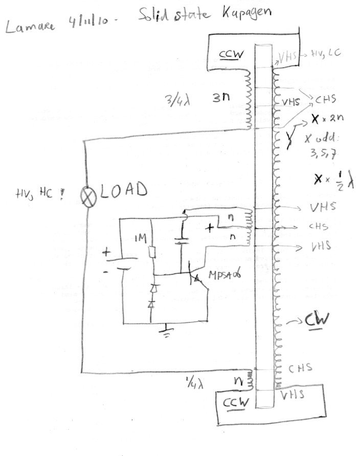
                            Some time ago, I posted some stuff on the Joulethief thread after analyzing the Kapagen device:

                            http://www.energeticforum.com/renewa...tml#post115135

                            There are some interesting references there about bifilar coils.
                            The principle is that there is a certain parasite capacitance between coil windings, which stores a certain amount of energy. By winding the coil bifilar, you get substantial bigger voltage differences between adjacent windings and therefore more energy is being stored in these parasite/self capacitances. Since the energy stored in a capacitor equals 1/2 C V^2 ( Energy Stored on a Capacitor ), this is a significant difference in the amount of energy that is being stored in the coils self capacitance. And since in resonance, this energy is being flipped back and forth between the capacitance (voltage) and the inductance (current, magnetic component) you get significantly stronger oscillations in there.

                            [...]

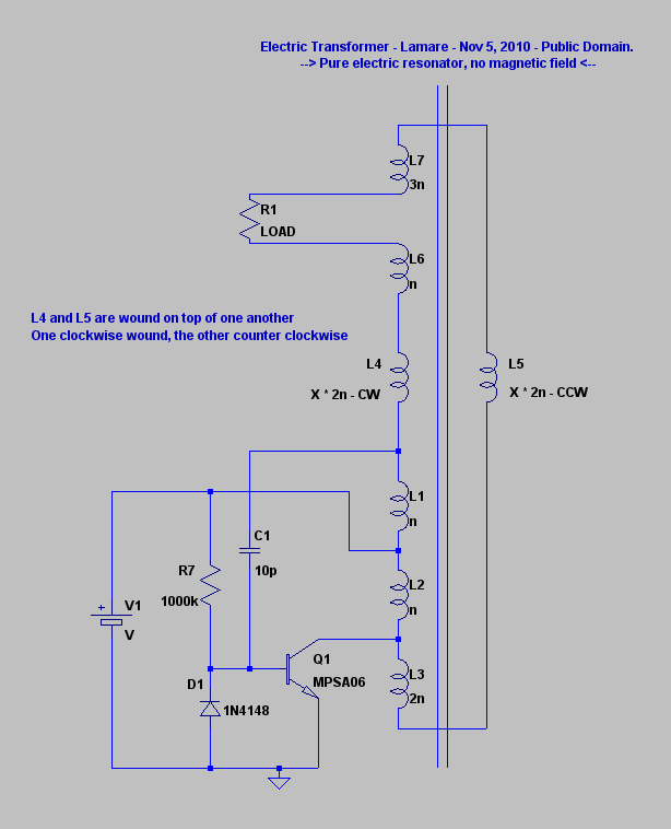
                            What is interesting is to compare Tesla's bifilar wound coil from his patent with the top/bottom coils in the Kapagen device. As you can see, Tesla connected them in series, in order to get the voltage difference, while in the Kapagen device they are wound CW/CCW. So, with Tesla's coil, the voltage difference between adjacent windings is distributed across the coil, while with the Kapagen device, this increases from top (connected part) to bottom. Given that with the Kapagen device, we have different length short coils at the top and the bottom, this suggests that you probably may use this principle also at higher harmonics with the Kapagen way of winding and still get this voltage gain effect. You see, with Tesla's way of winding, you only get the situation that the magnetic field caused by the currents trough each half of the coil cancel each other out at the half wave resonance frequeny (over the whole coil), while with Kapagen's, they seem to always(?) cancel one another out, or at least at more than one higher harmonic.

                            So, it seems that with Kapagen's way of winding, you can create a pure (longitudinal, "pressure-like") electric oscillation across the coil windings, without creating a magnetic field....

                            I also posted the idea for a solid state Kapagen device there:


                            Based on that, I came on this idea to use a dual layer coil, with one layer wound clockwise and the other counter clockwise, which would be L4/L5 in this schematic:

                            http://www.energeticforum.com/renewa...tml#post115219


                            Of course, these are not the same as the ringer circuit shown here, but maybe they are inspiring for further experiments....

                            Comment


                            • #89
                              Originally posted by SkyWatcher View Post

                              Well im surprised anyone here has achieved results at all, lasersaber has not bothered to clarify his circuit, nor has he mentioned exact resistances of his separate bifilar coil or wire gauges. That's fine if that's how he wishes to share. As for me, I would be sharing every last detail I could. Oh well, I'll still try and figure this out.

                              I think we should remember that

                              a) The holiday season (where folks have many obligations and duties) has only just finished
                              b) Lasersaber made a many part series ''how to build a Stubblefield coil'', at least an hour long, giving the most detailed description of how to replicate his Stubblefield coil rep.

                              Clearly Lasersaber is more than happy to share, and extremely helpful should you wish you replicate his work. Lets give the poor guy a chance eh? He's probably busy right now making a 12 part series on how to make various types of joule ringer for youtube

                              I've managed to get a 6W xenon tube working for 5-10 seconds after i remove the battery. Im using a flyback transformer instead of the fuji, and the bifilar seems to work best in the same position as i would normally put the base resistor. I have the output connected to HV +, and another pin on my flyback which seems to intensively arc after i remove the battery. Though honestly, i dont think this is the bifilar coil, and i dont think ive managed to replicate this effect. Have to keep trying today - its lots of fun!

                              Good luck

                              Comment


                              • #90
                                Hi folks, now were talking. I am now seeing the lasersaber 'joule ringer effect'.
                                Instead of a fluorescent for now, i decided to hook up a string of 20 leds and with a 6800uf 25volt electrolytic and charging cap with 6 volt battery, the cap lights the leds fairly bright then tapers off for about 2 minutes, then flashes rapidly for another 3 or so minutes. I used a high voltage diode i had from one of those information unlimited high voltage kits and i put a 1 megohm resistor in parallel with that and a nonpolar cap in parallel also. Much more tweaking to do i can see. Though i'm happy that I'm getting results.
                                peace love light
                                Tyson
                                edit: yes your right seth, forgive me if i sounded ungrateful. I'm happy with anything shared, thanks laser and all.

                                Comment

                                Working...
                                X