Announcement

Collapse
No announcement yet.

Joule Ringer!

Collapse
X
 
  • Filter
  • Time
  • Show
Clear All
new posts

  • Hi ehsan, ok i watched videos again, in second video he says 18 gauge litz wire and using one transistor.
    I'll have to see if that circuit using the negative on the transistor bases gets it to oscillate.
    peace love light
    tyson

    edit: ok that circuit does oscillate just fine. Must be because it just uses the potential difference and so a positive polarity is not needed at the bases since it has a negative polarity at the collectors is my guess.
    edit 2: ehsans posted douge tesla switch circuit is possibly showing some charge back to the 24 volt series input batteries or because the charge batteries are climbing, we'll see.
    Last edited by SkyWatcher; 12-23-2011, 07:37 PM.

    Comment


    • Originally posted by SkyWatcher View Post
      And have you built that tesla switch variant that you posted.
      peace love light
      tyson
      Hi Tyson

      I am working on it but I don’t have #16AWG 6 strand wire, I have only 2x16AWG coil so I intend to use this coil and if its work then i will wind 6x16awg air coil because i have the wire but Litz the 16AWG wire six of them is a real pain specially in a small apartment and i cannot do it outside because of the snow.

      Thank you

      Ehsan
      Take the wisdom even from the mouths of the insane

      Comment


      • Originally posted by SkyWatcher View Post
        Hi ehsan, ok i watched videos again, in second video he says 18 gauge litz wire and using one transistor.
        I'll have to see if that circuit using the negative on the transistor bases gets it to oscillate.
        peace love light
        tyson

        edit: ok that circuit does oscillate just fine. Must be because it just uses the potential difference and so a positive polarity is not needed at the bases since it has a negative polarity at the collectors is my guess.
        edit 2: ehsans posted douge tesla switch circuit is possibly showing some charge back to the 24 volt series input batteries or because the charge batteries are climbing, we'll see.

        Hi Tyson

        good to noticed that he is using #18 awg litz wire because at first when he start working on the circuit he used 18awg wire and that’s good also because I have 18AWG wire in my hand .
        I don’t think that there is a charge back to the 24v series but the charging batteries charged so fast , and I don’t know if this is a good sign or a bad sign because fast charging might harm the battery even if our charge is radiant spikes I guess.

        Good experimenting

        Ehsan
        Take the wisdom even from the mouths of the insane

        Comment


        • Hi ehsan, thanks for reply.
          I think 18 awg. litz wire means it is a total of 18awg. in thickness, though made up of many smaller wires to make the same diameter as a single 18awg. wire.
          Yes, I'm not sure on the charge back to input.
          Though this tesla switch variant is not only feeding radiant pulses to the charge batteries, it is also feeding regular pulsed current.
          So one pulse regular current followed by a radiant spike, repeat, etc., which is probably why it charges quicker and the 24 volt potential feeding it helps.
          Also, in dougs tesla switch video, his resting voltage was 12.5 volts.
          This may suggest his charging battery was not all that depleted, which may account for such fast climb in charge, maybe.
          Though since I am testing it as we speak, it does perform well and my input is only 160 milliamps because I have not adjusted the components yet to give more input.
          peace love light
          tyson

          Comment


          • Solar Panel for Joule Ringer / JB Charger 241211

            This is my mono crystalline 3.3 a 18 v solar panel initial run

            the 10 A controller has 2 output one 12 v 120w for my joule ringer and the other for jb charger


            ALKALINE POWER 9V DC BANK
            Uploaded with ImageShack.us
            Solar Panel Test for Joule Ringer/ JB Charger 251211 - YouTube


            Uploaded with ImageShack.us

            MERRY CHRISTMAS TO EVERYONE

            TOTOALAS
            Last edited by totoalas; 12-25-2011, 09:47 AM.

            Comment


            • Originally posted by SkyWatcher View Post
              Hi ehsan, thanks for reply.
              I think 18 awg. litz wire means it is a total of 18awg. in thickness, though made up of many smaller wires to make the same diameter as a single 18awg. wire.
              Yes, I'm not sure on the charge back to input.
              Though this tesla switch variant is not only feeding radiant pulses to the charge batteries, it is also feeding regular pulsed current.
              So one pulse regular current followed by a radiant spike, repeat, etc., which is probably why it charges quicker and the 24 volt potential feeding it helps.
              Also, in dougs tesla switch video, his resting voltage was 12.5 volts.
              This may suggest his charging battery was not all that depleted, which may account for such fast climb in charge, maybe.
              Though since I am testing it as we speak, it does perform well and my input is only 160 milliamps because I have not adjusted the components yet to give more input.
              peace love light
              tyson


              Hi Tyson

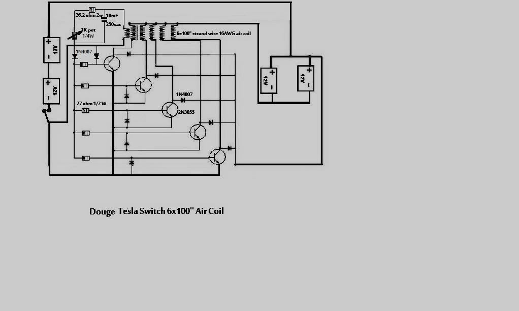
              I asked Doug about the wire gauge and how to litz it and he said that according to the schematic we should use 6x100 feet wire all #18awg and litz them all together and he used one of the wire as a trigger and the rest 5 wires will be the run and he used 2N3055 transistor.
              Here is link and you can read his answer:

              http://teep.forumco.com/topic.asp?TO...49&whichpage=3

              But in the video I am sure from the size of the coil I can tell that he used 2x100feet #18AWG litz wire not six wires.
              I build the circuit today but I used 10 filer litz coil 2x15feet #26AWG wires I connect them together and used them as a trigger and I connect the rest 8 wires together and used them as a one run wire and I used 1x2N3055 transistor and everything else according to the schematic and it seems that it charges well and fast.
              I didn’t use any resistor between collector and base and from emitter to base and I didn’t use any diode from emitter to base and I used the same modification Patrick did I mean the cap and the diode the same way he did.
              This is the circuit I used:


              Today was just a try and tomorrow will get some result.
              Regarding the resting voltage I think that he was taking about the charging batteries and he load them until 12v and after resting the voltage was 12.5.
              I wish I can ask him about the charging voltage after the resting.
              But we will try the experiment and see my self the result.

              Thank you

              Ehsan
              Take the wisdom even from the mouths of the insane

              Comment


              • PWM Current Limited French Flip Flop

                Some more progress on the Flip Flop current regulated at ground (-12) by a PWM controlled FET, operable from 70 mA - 1 A. Not a thing of beauty yet, but all one board / powersource, no rheostat, stable, no linear voltage regulation, no heat, and all one circuit.


                A better demo, improved, with circuit description:
                (3) "Wimpy" - A PWM Limited FLIP FLOP DC - AC Inverter - YouTube

                Here is the circuit powering (3) 2 watt AC LED lamps, with 390 mA (about 5 watts) on the end of a 50' Extension cord. Works Great. Using fixed resistors this time.
                (4) "Wimpy" - A PWM Limited FLIP FLOP DC - AC Inverter - YouTube
                Last edited by kcarring; 12-26-2011, 06:39 AM. Reason: add
                ----------------------------------------------------
                Alberta is under attack... http://rethinkalberta.com/

                Has anyone seen my Bedini Ceiling Fan that pushes the warm air down, and charges batteries as an added bonus? Me neither. 'Bout time I made one!!!!! :P

                Comment


                • JT Fast Charger


                  Uploaded with ImageShack.us
                  This is my first charger by Dodoshlodo and a video feedback from Thelron Stark tech guru in cap charging
                  the bigger the coils and lots of caps e capacity it can charge
                  I have two of these and use in my car in case of battery drain

                  hope you can try this or improve / check its performance

                  totoalas
                  Last edited by totoalas; 12-25-2011, 03:32 PM.

                  Comment


                  • Hi folks, Hi totoalas, funny you should post that, I was thinking of trying a capacitor dump again and try different cap sizes.
                    I don't think I have any triacs on hand, I wonder what else might work.
                    In circuit you posted, do all those transistors in parallel help the output to the capacitors a little.
                    peace love light

                    tyson

                    Comment


                    • "Wimpy" French Flip Flop Inverter

                      For anyone interested in experimenting with my mod "Wimpy" of the French Flip Flop inverter, here is the basic circuit, and breadboard shot:

                      http://img214.imageshack.us/img214/2082/wimpy.jpg
                      * there is a mistake on this diagram. pin 8 on 555 to 12V+, not drain on FETs as shown
                      Fuse protection is an absolute must in this circuit, because, for example if for some reason the output diode on the PWM fails, it will go into absolute current overload and start on fire LOL. So yeah, I learned that when i had forgotten to put that component in... a break in the circuit, at that point, is fatal, so do add a 1 or 2 amp fuse before using it, absolutely!

                      http://img692.imageshack.us/img692/1...breadboard.jpg


                      Only change is that i went from a pot to 2 fixed resistors. i was using a 500K pot before. I also added some capacitance on the power rail. Circuit seems to like polyester and tantulum caps.
                      I haven't done any math or put it on the scope yet so, I'll bet it can be improved a lot... I don't even know what frequency it runs at, but it works, never gets hot either, at all. Basically i think what is happening is the PWM gate is pulsed at higher frequency maybe 22k or something, limiting the inverters ability to source. The inverter is low frequency and in between slices, finds some current and still oscillates. Hums a tiny bit, but not annoying. I was told it wouldn't oscillate but it does. The cap on the power rail is high voltage and smooths out any flicker, and "gives a bit" helping it oscillate. Unlike a rheostat or linear voltage regulation method, the voltage stays higher, but is pulsed, so the current consumption drops. So does the RMS voltage, really, but, the coils still see full volts, each pulse therefore it runs on long AC cords, and does not heat up like the latter solutions. Nothing is even warm to the touch. That's my theory anyway, I'm not sure why it even works to be honest. Biggest disadvantage is that it starts to choke a bit at an amp or so, becomes inefficient. Thus the name "Wimpy". It is a limited use inverter for people wanted to run AC lighting off of 5-10 watt solar panels, basically. Should run for about 150 hrs on a truck battery, or 200 or more on a deep cycle RV battery. Best used from 3-700 mA, which was my target anyhow. Best advantage is its idle current is less than 75 mA, seems quite stable, I've run it for many hours already, and it offers a low power consumption inverter mod for off the shelf 2 watt bulbs. Should work with a variety of FETs, I just grabbed whatever I could find in the dump and everything/anything worked. Could use some spike protection I imagine.

                      A description of components is in the video description here.
                      (3) "Wimpy" - A PWM Limited FLIP FLOP DC - AC Inverter - YouTube

                      I've run the circuit for up to 18 hours straight and had no problems. Absolutely zero heat and no need for heat sinks @ 400mA and below, anyway.
                      I have the three lamps now running to stimulate the chickens to keep laying eggs 75 ft. away from the inverter, and 4 small 12V solar panels ($10 ea.) outputting 120 mA (each)
                      seem to keep up with it, quite well. A 10 watt solar panel would be ideal.
                      Last edited by kcarring; 12-27-2011, 09:47 AM. Reason: add
                      ----------------------------------------------------
                      Alberta is under attack... http://rethinkalberta.com/

                      Has anyone seen my Bedini Ceiling Fan that pushes the warm air down, and charges batteries as an added bonus? Me neither. 'Bout time I made one!!!!! :P

                      Comment


                      • Originally posted by SkyWatcher View Post
                        Hi folks, Hi totoalas, funny you should post that, I was thinking of trying a capacitor dump again and try different cap sizes.
                        I don't think I have any triacs on hand, I wonder what else might work.
                        In circuit you posted, do all those transistors in parallel help the output to the capacitors a little.
                        peace love light

                        tyson
                        Hi Tyson,
                        The purpose of the transistors are to cool them down and to rapidly charge the battery
                        Unfortunately Therlon Stark removed all his videos but lucky for me to test them right

                        I think the triacs and capacitors will do in the SSG for fast charging
                        since Stark said that bigger coils and more caps will boost the charging
                        Been looking for this cicuit for long time and dont want to loose it again
                        totoalas

                        Comment


                        • wimpy flip flop inverter

                          Originally posted by kcarring View Post
                          For anyone interested in experimenting with my mod "Wimpy" of the French Flip Flop inverter, here is the basic circuit, and breadboard shot:

                          http://img214.imageshack.us/img214/2082/wimpy.jpg
                          * there is a mistake on this diagram. pin 8 on 555 to 12V+, not drain on FETs as shown

                          http://img692.imageshack.us/img692/1...breadboard.jpg


                          Only change is that i went from a pot to 2 fixed resistors. i was using a 500K pot before. I also added some capacitance on the power rail. Circuit seems to like polyester and tantulum caps.
                          I haven't done any math or put it on the scope yet so, I'll bet it can be improved a lot... I don't even know what frequency it runs at, but it works, never gets hot either, at all. Basically i think what is happening is the PWM gate is pulsed at higher frequency maybe 22k or something, limiting the inverters ability to source. The inverter is low frequency and in between slices, finds some current and still oscillates. Hums a tiny bit, but not annoying. I was told it wouldn't oscillate but it does. The cap on the power rail is high voltage and smooths out any flicker, and "gives a bit" helping it oscillate. Unlike a rheostat or linear voltage regulation method, the voltage stays higher, but is pulsed, so the current consumption drops. So does the RMS voltage, really, but, the coils still see full volts, each pulse therefore it runs on long AC cords, and does not heat up like the latter solutions. Nothing is even warm to the touch. That's my theory anyway, I'm not sure why it even works to be honest. Biggest disadvantage is that it starts to choke a bit at an amp or so, becomes inefficient. Thus the name "Wimpy". It is a limited use inverter for people wanted to run AC lighting off of 5-10 watt solar panels, basically. Should run for about 150 hrs on a truck battery, or 200 or more on a deep cycle RV battery. Best used from 3-700 mA, which was my target anyhow. Best advantage is its idle current is less than 75 mA, seems quite stable, I've run it for many hours already, and it offers a low power consumption inverter mod for off the shelf 2 watt bulbs. Should work with a variety of FETs, I just grabbed whatever I could find in the dump and everything/anything worked. Could use some spike protection I imagine.

                          A description of components is in the video description here.
                          (3) "Wimpy" - A PWM Limited FLIP FLOP DC - AC Inverter - YouTube
                          Like your Build and hope to try this in the near future....Haven't posted in a while but watched your youtube video and was impressed with the circuit you came up with .Happy up coming new year to all....Tec

                          Comment


                          • Originally posted by Tectalabyss View Post
                            Like your Build and hope to try this in the near future....Haven't posted in a while but watched your youtube video and was impressed with the circuit you came up with .Happy up coming new year to all....Tec
                            Great! i'm sure many improvements / modifications can arise from this. i call it "Wimpy" for a reason, so it's not ideal for every situation, but in my case, it's serving well. There is no solar potential near the chicken coop, no power... so it's haul batteries, run long DC lines... or this...

                            I wonder if we can redirect the spikes back into the output? Anyone? I've not yet tried, and i get confused when it comes to diode configurations for moving spikes, BEMF, etc. where u want it...

                            In comparison to XEE2's Joule Thief.. I think that this may be actually "less" efficient, however it seems to supply more current as in my case; several bulbs in parallel. The flip flop is a rather crude, high output "kick ass" circuit... and it acts more like a conventional inverter; however without post inverter feedback, voltage regulation... it's a bit nasty too! This helps. For low output anyway. Whether or not the diode on the PWM need be an ultrafast high voltage diode, or not.. I'm not sure. I had a few and thought why not, seemed to be a point of vulnerability for the lifespan of the 555. I'm not sure what the voltage drop on it is, probably .7V - so that in itself will suppress the gate a bit more, too. The source of the PWM FET is straight up -12V, so the voltage drop shouldn't effect the flip-flop negatively. It may be that you can do the entire flip using BJT's but you'll definitely need a MOSFET on that PWM, I'd think.

                            Fuse protection is an absolute must in this circuit, because, for example if for some reason the output diode on the PWM fails, it will go into absolute current overload and start on fire LOL. So yeah, I learned that when i had forgotten to put that component in... a break in the circuit, at that point, is fatal, so do add a 1 or 2 amp fuse before using it, absolutely!
                            Last edited by kcarring; 12-27-2011, 09:52 AM.
                            ----------------------------------------------------
                            Alberta is under attack... http://rethinkalberta.com/

                            Has anyone seen my Bedini Ceiling Fan that pushes the warm air down, and charges batteries as an added bonus? Me neither. 'Bout time I made one!!!!! :P

                            Comment


                            • Flip Flop Inverter.

                              @Kcarring,

                              Zebok3, my Youtube handle, shows that 12 parallel 120 volt LED bulbs reduce source battery voltage with merely a minor increase in amp draw, over a single bulb, with the Flip Flop Inverter. My guess is a scope shot would show a phase shift between voltage and current that would help explain this anomaly. The Vellaman PWM has three pots: One to regulate voltage, the second frequency and the third, pulse width.

                              The Vellaman Flip Flop circuit, a seperate package, has two pots in place of the high value resistors to regulate the A.C. Hz. You may have noticed, as I did, that one side of the Inverter circuit's mosfets grows hotter then the other. Low resistor tolerance causes one side to run hotter then the other, even though the resistors share an equal rating; Hence the need for variables to achieve precise balance. I believe also, that the D.C. input frequency should match the A.C. output frequency, and that any change of voltage or pulse width alters the frequency; So, narrowing pulse width to conserve power requires a correction of the other values. Your 555 PWM is controlled by one pot, whereas the combination of the two Vellaman's gives us a grand total of FIVE! An oscillascope would help to tune that 5 pot combination light circuit to peak efficency. I built and tested the two circuits, but I'm on holiday in Costa Rica right now, and have to wait to finish my testing. I think you're on the right track, but your setup is kind of crude compared to the Vellaman PWM with it's 16 pin timer and 3 control pots. Source voltage has to be measured to calculate overall power consumption, along with amp draw.

                              Maybe you should send away for one. This circuit should permit us to tune current and voltage to optimum power phase. Mine was a snap to assemble and solder up, and worked flawlessly. That circuit will really put you in the driver's seat. These upgrades should turn "Whimpy" into a "Whopper"! I enjoyed your videos, thanks.
                              Last edited by Allen Burgess; 12-27-2011, 07:17 PM.

                              Comment


                              • Car Bulb Modified Capacitor Dump

                                Hi folks, I tested this circuit and it works well. It is a car bulb flasher circuit and I modified it to dump a capacitor charger.
                                The dump capacitor being charged from the flyback of a joule ringer.
                                I used a 24 volt battery to test with a car bulb in between the 24volt and 12 volt charge battery and get solid periodic pulses.
                                And the dump capacitor replaces the 24 volt battery.
                                Here is the circuit. Let me know what you folks think.


                                Uploaded with ImageShack.us

                                peace love light
                                tyson

                                Comment

                                Working...
                                X