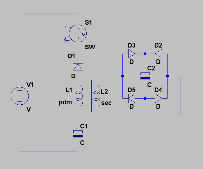
Hi all, i decided to go back to the SSG setup and try something i have been thinking about. My thought was to put an inductor with an iron core in the path of the inductive spike before it hits the charge battery. The idea was to see if i could give the wheel an extra push with the extra inductor but it did not really make a difference although it did create an extra magnetic field. What if found very strange was when the extra inductor was connected, the neon on the ssg circuit would flash bright and the charge battery would still charge. I added another diode to the new coil and it is now charging another battery. The primary charge battery has hardly been affected in it's charge rate and the second battery is charging just as fast. The input has also dropped by 90ma!
Announcement
Collapse
No announcement yet.
SSG Modification anomaly
Collapse
X
-
I replicated your findings. interesting indeed. I had a small bifilar coil from a previous experiment. core was some old nails. Im no expert using my scope yet, I have only had it since christmas. But my wave form changed. From the standard H wave to a slight H wave but with a considerably large negative spike before to positive H spike.
My current draw only went down maybe 10 mA. But the wire I was using was 26 ga. I was able to produce some Voltage in this config. The neon does light even though it is connected to charge battery. So i decided to try and utilize the transformer action of the bifilar. I put one wind of the bifilar in series with the output of the SG then to the charge battery. I used the other side of the bifilar to a cap. I could charge up a 50V 100uF cap almost instantly. I blew a small 12V auto bulb instantly off the cap. charge rate stayed the same throughout the experiment. SG did not slow down throughout the experiment either.
-
Excelent work Zooty that is very interesting, the spike hitting the coil causing the neon to flash, solved with another recovery diode, awesome experiment. Please do keep up the experiments, and keep us informed.
Every bit of insight is helpfull to someone.
Cheers
Comment
-
Originally posted by minoly View PostVery nice
have you checked out Energy From The Vacuum - Part 7 - Tesla's Impulse Technology?
it will explain what's going on.
Edit:
If you have an ammeter connected to the positive of your source, make sure you connect the negative of the charge battery to the source positive after the ammeter so that you can measure the drop in input current. The SSG circuit pushes current back to the primary. If you connect the charging battery directly to the source positive terminal, you are bypassing the ammeter.Last edited by Zooty; 01-04-2011, 02:26 AM.
Comment
-
Originally posted by Zooty View PostHi Minoly, this is very different from the Tesla Impulse Technology that John showed in that video. He uses a bridge rectifier directly across the power coil and the extra inductor has an air core. What i wanted to do was take advantage of the inductive spike because it does not seem to loose strength as it travels through a conductor unlike normal hot current. I also noticed that depending on the load after the extra inductor, dictates how much current is generated in that inductor. The other thing to think about is, the extra inductor now also produces it's own inductive spike from the main inductive spike without any waste. When the main spike creates a dipole across the coil in series with the charge battery, current flows, creating a magnetic field in the extra coil. The spike is a very fast pulse with a nice sharp off so there is time for the field to collapse creating another spike and it seems to be free of charge because the charge battery sees all of it as if the inductor was never there I am wondering now if i can add several coils like this to make extra spikes free. I still don't understand how the neon can light up when the extra charge battery is disconnected
Edit:
If you have an ammeter connected to the positive of your source, make sure you connect the negative of the charge battery to the source positive after the ammeter so that you can measure the drop in input current. The SSG circuit pushes current back to the primary. If you connect the charging battery directly to the source positive terminal, you are bypassing the ammeter.
now you said something that caught my eye. are saying your amp draw goes down when you add this inductor? or did I read wrong?
try putting that inductor on the negative leg of the primary battery, due to the core, and increased inductance the current is slowed - the radiant has a chance to build up, then you will see your neon will glow white, we actually blew a couple last year. this is something discussed over on BM2 yahoo.
Thanks for sharing
Comment
-
Originally posted by minoly View Postyou can use a single diode or a whole FWBR. the process is the same. the difference you have is the core/increased inductance of your coil. Even if you put a bridge your neon will light w/o the additional charge battery. so the SG ckt is expecting it. you answer your question when you said they are somewhat in series.
now you said something that caught my eye. are saying your amp draw goes down when you add this inductor? or did I read wrong?
try putting that inductor on the negative leg of the primary battery, due to the core, and increased inductance the current is slowed - the radiant has a chance to build up, then you will see your neon will glow white, we actually blew a couple last year. this is something discussed over on BM2 yahoo.
Thanks for sharing
This modification does not drop the input as much as i thought it did. I realized the first time i connected it, i had the charge return going straight to the source positive before the ammeter so it was showing only current leaving the source. By connecting the return after the ammeter i was reading 90ma less than before. I then realized that this must be a characteristic of the normal SSG circuit. It does in fact push around 90ma back to the source but it has to be pushed through the ammeter to see it. I still think there is something here because the charge rate is much higher with the extra inductor and no increase in input.
Comment
-
this is how words can get all discombobulated
I was comparing your add on the the "nodes" JB talks about starting at around the 7 minute mark, not the main power coil.
there is something here - keep up the good work. you got us all excited about trying it your way, will have to do it in the AM. I'm known to let the smoke out of things in the late hours
Comment
-
Originally posted by Zooty View PostHi all, i decided to go back to the SSG setup and try something i have been thinking about. My thought was to put an inductor with an iron core in the path of the inductive spike before it hits the charge battery. The idea was to see if i could give the wheel an extra push with the extra inductor but it did not really make a difference although it did create an extra magnetic field. What if found very strange was when the extra inductor was connected, the neon on the ssg circuit would flash bright and the charge battery would still charge. I added another diode to the new coil and it is now charging another battery. The primary charge battery has hardly been affected in it's charge rate and the second battery is charging just as fast. The input has also dropped by 90ma!
It looks like the excess energy observed in Bedini's SG, Gray's motor, Meyer/Puharichs WFC and the so called Tesla switch all have something to do with what Tesla called a "distruptive discharge", a spike, into a coil in series with either an electrolytic cap, a battery or a WFC:
http://www.energeticforum.com/renewa...tml#post124382
If indeed the ions inside an electrolytic cap cause a delay for currents to flow, then you have the essence of what Gray was doing. A HV sudden discharge into a coil causing a magnetic field because of the changing electric field during a short moment where there is not yet a current flowing, which is possible because the other terminal is loaded with some device containing an electrolyte fluid in between metal plates: an electrolytic cap, a battery or a WFC.
If that is the key mechanism, basically using a changing electric field to create a magnetic field inside a coil while delaying the moment a current can flow, because of the use of a device containing an electrolyte, then there may be a way to close the loop after all. This would be something like this in the way Gray did it:
However, Zooty's extra (green) coil could of course also be the primary of a transformer, while the secondary could be used to charge the source battery without directly closing the loop.
I came to this idea, because according to Mark McKay, the batteries were essential in Gray's stuff, and there are also a few strange (electrolytic!) capacitors in Bedini's schematic of the so-called Tesla switch:
http://www.energeticforum.com/renewa...tml#post123651
Mark McKay posted some information on the earlier, succesfull, Gray engines which I think is very important also for understanding the Tesla switch:
Originally posted by Spokane1 View PostThere is meaningful observation documented where the non-classical output was a simple, but huge, DC spike that recharged the storage capacitor(s) and was also directed towards the storage batteries. The batteries were destroyed by this input -BUT they could not be eleminated from the circuit. Their circuit parameters were a requirment for non-classical operation. The motor could never run "closed loop" becasue the energy that was not extracted in the form of torque couldn't be effectively stored. They only needed a 60A alternator to top off the batteries from a functional standpoint. But if the motor ran for more than 30-60 minutes the batteries were toasted. If the motor was ran longer than this they exploded from hydrogen outgassing. Today this challenge might be solved with some huge carbon foam capacitors and sophiscated switch-mode power supply circuits.
Just like I wondered what capacitor 38 in Grays circuit is for, I also wondered why there are capacitors in the lines to the diode bridge in the most original working Tesla switch schematic I know of, the one on page 8 here:
http://www.tuks.nl/pdf/MUELLER_EXPER...SLA_BEDINI.pdf
As you can see, this one powers an inductive load, a motor, while being fed trough electrolytic capacitors in the line to the rectifier bridge.
It appears that devices containing metal plates with a water solution in between them, be it a battery, an electrolytic capacitor or a WFC, in combination with an inductor are essential for obtaining excess energy.
As I posted here, according to the Maxwell equations, a magnetic field can not only be caused by a current, but also by a changing electric field:
http://www.energeticforum.com/renewa...tml#post123467
Maxwell's equations - Wikipedia, the free encyclopedia
Ampère's law with Maxwell's correction states that magnetic fields can be generated in two ways: by electrical current (this was the original "Ampère's law") and by changing electric fields (this was "Maxwell's correction").
Maxwell's correction to Ampère's law is particularly important: It means that a changing magnetic field creates an electric field, and a changing electric field creates a magnetic field. Therefore, these equations allow self-sustaining "electromagnetic waves" to travel through empty space (see electromagnetic wave equation).
Interestingly, Bedini uses the same principle the other way around. He energizes a coil trough a transistor and then suddenly switches the transistor off, so no current can flow trough the transistor anymore. He redirects the sharp rising voltage at the coil terminal trough a diode to a charging battery. And then you get a DC spike, exactly because the ion based current inside the battery takes some time to react.
So, it appears that with electrolytic capacitors, you get a short delay between the moment a field, a voltage, is applied to it and the moment a current starts flowing. And it appears this effect can be used to cause a magnetic field to build up inside a coil, without providing current to it, while the energy that has been build up in the coil can be harnassed for free.
Given that Gray's system includes a capacitor 38 and his schematic supposedly originate with Tesla, and Marvin Cole could not get this system to work without batteries, one can speculate that the plate distance of the electrolytic capacitors/batteries used is an important parameter for the effects we are after. And therefore it seems likely that old school electrolytic capacitors, basically aluminum plates in an electrolyte solution, offer the best results.
For more on how to make old school electrolytic capacitors as well as rectifiers, see: http://www.energeticforum.com/renewa...tml#post123445
Comment
-
And therefore it seems likely that old school electrolytic capacitors, basically aluminum plates in an electrolyte solution, offer the best results.
For more on how to make old school electrolytic capacitors as well as rectifiers, see: How to make a diode?
Wouldn't they just be layden jars, or are they different ?
The evidence does seem to be there that this is important. It is already known that layden jars are a very important part of the conversion of for want of a better word "static" or purely potential energy to usable electricity.
They are used in the testatika machine, apparently with success.
Very interesting stuff.
Cheers
Comment
-
Originally posted by Farmhand View PostWell lamare, I believe your explaination does make sense to me. We need some folks to spend some experiment time refining the easiest and most effective ways to make and rate these "old school" electolytic capacitors.
Wouldn't they just be layden jars, or are they different ?
The evidence does seem to be there that this is important. It is already known that layden jars are a very important part of the conversion of for want of a better word "static" or purely potential energy to usable electricity.
They are used in the testatika machine, apparently with success.
Very interesting stuff.
Cheers
Electrolytic capacitors are different from Leyden jars, because in an electrolytic capacitor, one of the capacitor plates is not really a "plate", it is a fluid, the electrolyte.
So, you have one plate, usually aluminum, on which a very thin layer of dielectric material has been formed. And that is basically what the glass is in the Leyden jar, only this is much, much thinner, which is why you can get a much higher capacitance.
However, the other "plate" is at the other surface of this same very thin layer, so in order to get this "plate" charged, you have to get get charged ions inside the conductive fluid to move towards the surface of this unsulating layer.
So, with a normal capacitor, you have metal plates acting as the capacitor plates, while with an electrolytic capacitor, one of the plates consists of ions in a fluid.
Comment
-
Zooty
I also tried adding a coil (#24 800 winds with bolt for core) to my charging circuit. Neon did not come on. But then I have the Bedini inverted circuit across
the terminals of the charging battery. Hoping to get improved results. It is very
interesting what you have found !
FRC
Comment
-
Thanks lamare, thats very helpfull. So much to learn.
lamare said,
So, with a normal capacitor, you have metal plates acting as the capacitor plates, while with an electrolytic capacitor, one of the plates consists of ions in a fluid.
Rgds
Ok so the " how to make a diode" link explains it all beutifully, thanks again.Last edited by Farmhand; 01-04-2011, 11:49 AM.
Comment
-
Originally posted by Farmhand View PostThanks lamare, thats very helpfull. So much to learn.
lamare said,
Ummmm, since its electrolytic, which plate is which ? I'll have a guess ! Is the fluid the positive ?
Rgds
In normal operation, the positive plate is the one that grows a dielectric layer, so then the fluid would be the negative. In that mode of operation, at the negative plate (if it is aluminum) you also have such a layer, but it is that thin that it easily breaks down and electrons can flow into the fluid, charging it negatively.
And an old school rectifier is almost the same. Only then the negative plate is another kind of metal, one that does not form a protective layer. See:
Baking Soda Variable Electrolytic Capacitor.
Borax or Baking Soda Rectifier and the glow.
Comment
-
could this be the same thing going on in the JouleRinger thread with the use of electrolytic caps the extra bi-filer winding and Teslas Impulse Tec all ringing the bell in tune with each other shuttling the energy around while we pick off bits here and there?
Comment
Comment