Announcement

Collapse
No announcement yet.

Toroidal Power Amplifier

Collapse
X
 
  • Filter
  • Time
  • Show
Clear All
new posts

  • Toroidal Power Amplifier

    Hi folks,


    see attatchment,

    i just got through constructing a reasonably crude construction of "variant-6" ( see pdf ).

    using both sine waves & pulsed DC from the function gen, i could get 6 LED's to light etc.....but it didnt WOW me like i was hoping it would.

    i was using 20 turns of 24SWG for winding-I, 10 turns for each of the winding-II, and some thicker SWG 20 about 10 turns again for winding-III.

    I was using toroids taken from PC power supplys, probably powdered iron or some such. With an input of a sine wave i did get a sine wave output on winding-III. however i was inputting around 15V and only getting around 1.3V out ( i know V-to-V is no measure of efficiency ).

    anyone else got any ideas ( after reading the pdf )......or does anyone else want to have a crack at a build that has better parts than i do?

    Thanks

    David. D
    Attached Files

  • #2
    Interested

    Yes, I am interested. Right now I working on a circuit using caps from computer
    power supplies. So I have lots of those toroids left over. Would be nice to be
    able to utilize them too.

    FRC

    Comment


    • #3
      FRC, have a crack at it.........mine wasnt the prettiest build to be sure.,....i got it done as quick as possible.

      id love to see someone else have a go.

      Comment


      • #4
        HI Rav I'm fairly new to all this stuff ,but i was under the impression that the secondary windings were always more turns than the primarys......maybe I'm not reading things right.....am very interested in this stuff as I am trying to enhance the voltage supply I have ,I'd like to charge multiple cap banks off of one supply if thats possible.....very interesting stuff...........shylo

        Comment


        • #5
          @ shylo, secondary windings can be whatever you want depending on what translation of primary voltage to secondary voltage you desire.

          @ all, first..have a read through this http://www.distinti.com/docs/classfluxan.pdf and also the pdf i attatched in my first post.

          with al that in mind, i have made a setup based on "varient-2" in the toroidal power amplifier pdf...

          also i have added another coil onto the right-hand toroid, meanwhile the middle coil (winding-II) is wrapped very loosely.

          winding-I is 38 turns of 26SWG, winding-II is around 15 turns of the same and winding-III is 38 turns of 22 SWG.

          i am in-putting 9.9V pulsed DC at 50% duty cycle directly from the function generator. Also the DC offset is set to "middle" position. Frequency is 1.089 MHz.


          SETUP-1:-
          with the toroids as far apart as possible and therefore the winding-II as close as possible to toroid-1 and also close as possible to toroid-2 i get..

          9.5V RMS , 26.7V p-p

          SETUP-2
          with winding-II still tight to toroid-1 but moving toroid 2 so that winding-II is thread through the middle of it and not touching i get..

          10.3V RMS , 28.9V p-p

          moving both toroids so that winding-II is not touching either of the toroids i get..

          15.0V RMS , 39.8V p-p

          attatched a diagram to more explain
          Attached Files

          Comment


          • #6
            A suggestion.

            Try making the loop that goes through both toroids as square to the planes of the toroids. This would be a quasi figure 8, only with the central line cut out.

            Another avenue would be to twist the toroids after winding the center loop making a bifilar type flip of the fields in between the toroids.

            Also another good suggestion would be to install a harness made of plastic that allows you to wind it and keep it precisely where you want the wind to go. I can see a weird method to that winding considering you would have to wind it in a figure 8 pattern. The wind in between the toroids would be stacked up pretty much one on top of the other making an intricate weave. The ends going through the toroids would be not so organized. You are not talking about 500 feet of wind here. The plastic jig once made would be unique to those two toroids so that will take some doing. It sounds like to me you are getting better results from the third choice or example. Making a jig would help tremendously in bringing your setup some stability and should make things more interesting.

            Comment


            • #7
              Making a "spool" out of old CD boxes, hopefulyl it will hold the wire and enable more precise placements/measurements.

              Hopefully some of you have had a flick through the 2 pdf's posted, theyre quite interesting, especially the one that explains "how" flux moves into & out of a toroid.

              Comment


              • #8
                Oh I have read it...

                Originally posted by rave154 View Post
                Making a "spool" out of old CD boxes, hopefulyl it will hold the wire and enable more precise placements/measurements.

                Hopefully some of you have had a flick through the 2 pdf's posted, theyre quite interesting, especially the one that explains "how" flux moves into & out of a toroid.
                Oh I indeed read the pdf's and this rings true. It explains transformers fully and it has a good amount of information about flux. Absolutely a must read.

                I would think there is more to it then that also. Think about the ball we live on. Flux must be everywhere in high density. It would explain what magnets are and how they operate to hold the borrowed flux from our huge ball and hold them in the organized channels we configure them into. Magnets seem to be the holder of flux lines once organized. Complete circular flux lines.

                Comment


                • #9
                  ok, i re-did my build using the home made spool, replicated the results.... however...i think its going to take bigger cores than i have. Need to pump a bit of power into this thing to see if theres anything really there.

                  Comment


                  • #10
                    I have just got my hands on two big toroid transformers, 1kVA each.


                    The original windings are still there.
                    As you can see a have sandwiched them and put one white winding around them both just for starters.
                    This should correspond to "variant 2".

                    The setup is a variant of Thane Heins BiTT
                    YouTube - MIT Dr. Zahn Bi-Toroid Transformer (BITT) Tutorial 101.mov

                    and also of this:


                    The only testing so far have been pulsing them (pulsing is always fun),
                    but I have no reliable measurements yet to share.

                    As soon as I have something that at least i can replicate, good or bad, i will post it.

                    /Hob
                    Hob Nilre
                    http://www.youtube.com/nilrehob

                    Comment


                    • #11
                      nil,

                      thanks, glad someone could get theyre hands on some "big" stuff to play around with.

                      Not sure what will come of all this ( if anything )....but so far i see this....

                      Current in W-I (winding-I ) is translated into flux into the toroid which by virtue of W-II being wound "through" the toroid is cut by the flux and has a voltage/current induced into it , however....unlike a normal transformers secondary where that induced voltage/current would produce a flux in the opposite direction to the primary flux......in this case that scenario is avoided......so yes.....it IS a little like thanes BITT.

                      I have a feeling that i needed to put more windings on my toroids both primary and also W-II.....which as i said is difficult due to their small size.

                      i might have a crack at molding my own cores using Fe304 and resin (which i have )......but its yucky stuff and would also need some crushed ferrite/iron filings to increase its flux density capacity......so a bit yucky all the way round.

                      I look forwards to what you can do/show with those huge looking toroid cores !! ( where did you get those btw?....and how much were they? )

                      Thanks

                      P.s ye si can see how your two toroids correspond to "variant-2" :-)

                      David. D
                      Last edited by rave154; 01-26-2011, 02:41 PM.

                      Comment


                      • #12
                        A thought just occured to me, so i thought i would sketch it out for comments.

                        see attatched.

                        As before, current in Winding-I is translated into flux which in turn "cuts" winding-II (but by virtue of winding-II NOT being closely wound around toroid-1 DOES NOT induce a counter-flux which would give rise to all the normal degredations that happen when shorting the secondary of a transformer )

                        The Flux cutting winding-II induces a voltage/current in proportion which in turn creates a flux in toroid-2(and winding-II IS tightly wound around toroid-2) BUT.....because of the double wrap that winding-II has around toroid-2 doubles...and thus creates a bigger output in winding-III.

                        Thoughts?
                        Attached Files

                        Comment


                        • #13
                          I'm not so sure about flux cutting through windings anymore, at 5:55 in
                          YouTube - Part 4 of 6: Eric Dollard & Chris Carson Tesla Longitudinal Wave Energy SBARC Ham Radio

                          well, I'm not so sure about anything anymore

                          /Hob
                          Hob Nilre
                          http://www.youtube.com/nilrehob

                          Comment


                          • #14
                            You know he is right.

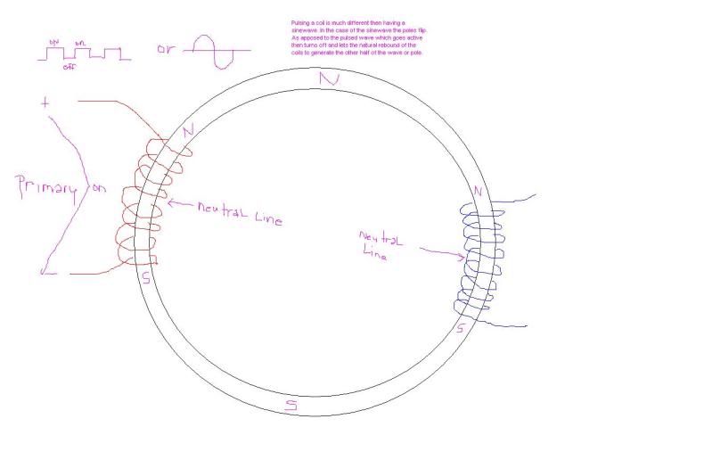
                            Wow I just realized what Tesla was saying is going on in a toroid. The flux is indeed contained withing the core if it is not saturated. But there are lobes that get formed that have a north and south orientation to it. Think of these lobes as a slippery lobe of north field and south field. They extend out of the ring and meet on the other side of the energizing coil.

                            Just like we have on a straight piece of core there are field hot spots and on a toroid these hot spots are outside of the core. When you energize the toroid's primary the lobe on the top will be north and the lobe on the bottom is south for instance. When the energizing signal is an ac signal this causes a flipping of the north and south.

                            If someone skilled in the art of illustration could put an animation together that would be helpful. I'll try my best to draw up some pictures and put them on my host and link them here in the meantime.

                            Lets discuss this as I don't have the full grasp of the situation and would like to try to get to the bottom of this discovery.

                            Maybe this will help:

                            Last edited by Jbignes5; 01-26-2011, 05:38 PM.

                            Comment


                            • #15
                              nil, re -read & look at the diagrams of the pdf..... it will hit you

                              as the flux from the primary "enters" the toroid core.....it ZIPS around the core to try and complete the magnetic circuit....as it does so it "drags" the part of the flux circuit that is in the air with it....and THATS the part that cuts the secondary.........no matter "where" the secondary is wound as long as the secondary goes "through" the toroid. This explains WHY the secondary windings DONT have to be TIGHT against the toroid....they can even be a long way away from it in the middle of the toroid....and they STILL produce the same power.

                              However.....IF you wind the secondary TIGHT to the core........you will still get the same current/voltage induced into it ( you will get this no matter WHERE the secondary is )......but when its tight to the core......the secondarys current will induce a counter flux thats in opposition to the primary flux......or at the very least will induce a flux that takes up space in the toroid and thus raises the current drawn from the primary.

                              the pdf EXPLAINS the very question asked in the eric dollard video. ( thats how i kinda found it .....sort of )
                              Last edited by rave154; 01-26-2011, 04:49 PM.

                              Comment

                              Working...
                              X