Announcement

Collapse
No announcement yet.

Donald L. Smith

Collapse
X
 
  • Filter
  • Time
  • Show
Clear All
new posts

  • #91
    Originally posted by nightwind View Post
    Thanks for clearing my fuzzy thinking. You didn't say opposite, but I thought that was what your arrows were implying.
    Oh ok, no prob's, you mean the top transformer, there are two primaries in a transformer
    for making AC from DC they are pulsed with almost 50 % duty one primary
    has the positive and negative connected as per normal and the other has the
    positive and negative reversed usually the positive is the common and the
    negatives are switched alternately at close to 50% duty to give an AC wave
    form. I think the positives can be switched and a common negative used
    instead. It's meant to be an iron cored transformer. Both primaries are wound
    the same way just the polarity of the connections is reversed.

    That's what the drawing indicates, there is a 1 and a 2 marked for the two phases.

    The drawing is still only a concept drawing, nothing should be considered
    working unless shown to be working.

    Sorry about the messy drawing.

    Cheers
    Last edited by Farmhand; 02-27-2012, 04:29 AM.

    Comment


    • #92
      Function generator fun. Bodgy equipment and dodgy user make for a head
      shaking time. I post it just in case someone see's something I don't.

      The "solid band of power" comment was a joke by the way. Seemed funny at the time.

      DS coils function generator test (power band?) - YouTube

      Cheers

      Comment


      • #93
        Here's some links to info for stepping down very high voltage by using
        capacitive methods to reduce the voltage one is by a divider method then
        transforming it with a regular transformer. May be there is something useful in
        them for us.

        PDF
        http://www.ipst.org/TechPapers/2005/IPST05_Paper076.pdf

        PDF
        http://www.zen22142.zen.co.uk/Analysis/analysis.pdf

        html. Tesla type setup for step up I think.
        A capacitive transformer Tesla coil

        Google search
        Google

        PDF
        http://www.google.com.au/url?sa=t&rc...U-dk_fva97eUvA

        Cheers

        P.S. I just found the word "above" followed immediately by the word "unity", it in the second PDF I linked at the bottom of page 7.

        Design of a grounded-base AF Colpitts oscillator

        Sine-wave oscillator configurations basically differ from each other in the way signal
        voltages (or currents) are fed back from the output port to the input, while loop gain is
        maintained slightly above unity. The Colpitts oscillator, for example, operates
        successfully thanks to the correct capacitive tapping of the signal voltage existing
        -7- across the L-C tuning tank. It constitutes an excellent example of application of the
        capacitive transformer in an oscillator circuit.
        ..
        Last edited by Farmhand; 02-27-2012, 07:58 AM.

        Comment


        • #94
          wow

          Originally posted by Farmhand View Post
          Hi Nightwind, You mean the air core coils of the main device ? Yeah they are
          both wound the same way as if from one coil, mine are both CCW wound so is
          the primary. Because the L2 center tap is grounded one coil goes high while
          the other goes low, by that I mean the center tap is grounded so it is 0 volts
          the left coil goes high a positive voltage while the right coil goes low a
          negative voltage (if they were connected they would cancel each other out).
          Then because they are resonant they swing both ways so when the
          left one goes low a negative voltage the right one goes high a positive.
          However when they get half wave rectified only the positive portion charges
          the cap (kind of) with only one coil this would halve the duty or (cap charge time)
          but with two coils the duty of both halved is the same as the original 100% duty.

          If the coils were wound opposite as in CW-CCW then the positive and
          negative voltage of both coils would be at the same time, so when they are
          both half wave rectified the duty is still reduced to 50% cap charging time.

          Half wave rectifying retains voltage but halves the duty, full wave rectifying
          halves the voltage but retains the duty. When we measure AC volts we only
          measure one way from zero or one side same with frequency 60 Hz is 60 up
          and 60 down. I think. If we full wave rectify a perfect AC square wave we fold
          the voltage wave form in half horazontally and end up with a flat line of DC at
          about the same voltage as the AC reading. With a sine wave we end up with
          a series of bumps, if a sine wave is half wave rectified while the negative end
          of the coil is grounded we end up with the AC voltage x 2 but only for half the
          time. It gets complicated when the reference point is moved.

          Cheers

          P.S. I think I see what you mean now, the current through both sides of the
          coil goes the same way at the same time (not opposite) I didn't say that it
          went in opposite directions at the same time I don't think.
          But because the coils are on opposite sides of the primary the
          voltage induced is opposite and alternating at the same time. I did this with
          two Tesla coils by connecting two identical Tesla coils secondary bottoms to
          ground then connecting the primaries in series but reversed the connections
          of one of the primaries and put the spark gap between them, they produced
          opposite voltages as we would expect. If you could scope it at both ends
          (two probes) at resonance you would see is a pair of crossed sine waves like
          a DNA helix.

          ..
          you do great work man, and love your cap pulser vid, soo cool
          In the beginner's mind, there are many possibilities.
          In the expert's mind there are few.
          -Shunryu Suzuki

          Comment


          • #95
            Thanks mr.clean, Here's another video. In this one I use all the power of the
            little HV supply, as I increase and decrease the power you can hear the spark
            gap change tone briefly each time the spark frequency increases and decreases.
            It sounds kinda cool, I'm not sure what to make of that waveform. It looks like
            groups of about 5 or so discharges at full power.

            DS Waveform -3-3.wmv - YouTube

            Cheers

            Comment


            • #96
              Originally posted by Farmhand View Post
              Very usefull info Boguslaw, these are definately very similar setups. Resonant capacitor sounds good.

              It looks to my untrained eye that to get these systems to really sing. We need to construct them close to what is needed for resonance. Then simply adjust the spark gap distance and tune the capacitor in the primary circuit. Some trial and error and plenty of hair to pull out should finish the process. Hows that sound ?

              I'll take some note's from these posts of yours and compile a work file I think.
              Also I should keep a book for recording and collating building and tuning data aswell.

              I already have a coil 1mm wire x 3 inch diameter x 13 turns. Should the secondary and primary be bare copper ? Maybe. And should the secondary be wire 1 mm too ? Like same AWG wire . If 1mm is not thick enough what would be ?
              always great info from you, youre saying you dont have an nst, what area do you live? hehe with what you know, you could wind your own

              just checking out some of your vids, lots of work, until recently i didnt know you had vids, i agree with someone earlier, looks like Tesla's lab
              In the beginner's mind, there are many possibilities.
              In the expert's mind there are few.
              -Shunryu Suzuki

              Comment


              • #97
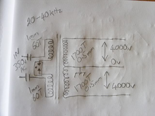
                Hi all, Some more parts have arrived for another very similar setup I want to
                modify, I plan to make the setup in the drawing below, I power it directly from
                my converter with either AC or rectified to DC not sure yet, I have some mini
                spark gaps which break down at about 280 volts and if I use my converter at
                between 20 to 40 Khz, the outputs which are 240 volts at 60 Hz are almost
                400v at the higher frequencies due to resonance. I should get about 8000v from
                the secondary of this with 4000v - 0v - 4000v and Earthed center tap. The
                primaries of this setup will go inside the secondaries, the secondary sides will
                be separated and the primary leads will exit from between the coils, but there
                will be two primaries closely coupled to the secondary halves and they will be
                in series too so will also have a center tap or able to take a center spark gap
                (break). At this point I think I will try a core of steel wires or I might buy a
                large ferrite/iron powder rod. That's if it won't work good enough air cored.

                EDIT: I wasn't able to make this circuit work, not sure why yet but I will get back to it later to investigate and try to find out why not.


                Cheers
                Last edited by Farmhand; 03-02-2012, 02:55 AM.

                Comment


                • #98
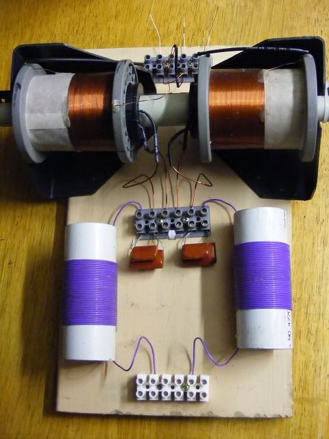
                  Here it is, I'll test it with 350 volts at 36 Khz tomorrow. The little white thing
                  between the caps is the spark gap, hope it works. Looks very promising. If I
                  put the primaries in anti parallel the voltage is a lot more and the max voltage
                  is at 40 Khz. Primaries are in series at the moment with the spark gap
                  between them.


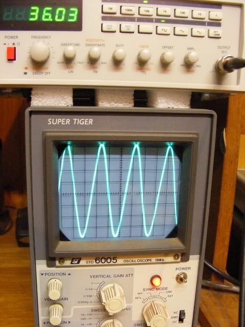
                  Scope is set to 10 volts per division and function generator is at 4 volts amplitude signal.
                  Only one side is probed to center tap. Maximum voltage is at 37 Khz or so.


                  P.S Here's a short video. Home made NST replacement maybe - YouTube

                  ..
                  Last edited by Farmhand; 02-28-2012, 06:44 PM.

                  Comment


                  • #99
                    Originally posted by Farmhand View Post
                    Thanks mr.clean, Here's another video. In this one I use all the power of the
                    little HV supply, as I increase and decrease the power you can hear the spark
                    gap change tone briefly each time the spark frequency increases and decreases.
                    It sounds kinda cool, I'm not sure what to make of that waveform. It looks like
                    groups of about 5 or so discharges at full power.

                    DS Waveform -3-3.wmv - YouTube

                    Cheers
                    very cool! yes it looks like 5 building and firing cycles in the space of 1 or 2, that is operating fast!

                    and i have tried those little surge arrestors, its strange, for a while a small 350 volt worked best, then a 6kv, but im back to the exposed gap, if you have the right value it may work, needed the adjustability
                    Last edited by mr.clean; 02-28-2012, 07:46 PM.
                    In the beginner's mind, there are many possibilities.
                    In the expert's mind there are few.
                    -Shunryu Suzuki

                    Comment


                    • any advice?

                      prob seen it already, this my most recent vid, since this it has improved with different primary and secondary wiring and adding FERRITE!!

                      but im looking for higher freq and im starting to think the ignition coils are not going to cut it. just when i get to 20khz, the power out of the circuit dives.

                      anyway like i said it has improved, but still in progress, just need some more lights now and igbt's

                      Don Smith Device Project Part 20c: Transient Spikes Powering Load From TOP, down - YouTube

                      am i correct in saying transient spikes?

                      also im planning on IGBTcap pulsing 60hz from the output caps to load,,, unless stepdown transformer is better?

                      any questions or comments or advice?
                      Last edited by mr.clean; 02-28-2012, 07:42 PM.
                      In the beginner's mind, there are many possibilities.
                      In the expert's mind there are few.
                      -Shunryu Suzuki

                      Comment


                      • Hi, I am currently running two of these ecore in anti parallel.

                        FIAT PUNTO 0.9 1.1 1.2 IGNITION COIL PACK PAIR X2 SET | eBay

                        The sparks are far superior than the oil filled single tower coils and I've tried 3 different brands.

                        You will be impressed if you get them.

                        The best bit about these coils is:

                        a) the price
                        b) most importantly the primaries are totally isolated from the secondaries.
                        c) a good fat chunky earth can be fitted for the centre tap between the two coils twin towers.
                        d) they can easily be mounted on a bracket.
                        e) can be voltage, frequency, duty controlled.
                        f) tested up to 100khz
                        g) powerful spark for the money (I was quite shocked when I fired one up and saw the arcing between towers.)

                        Downside

                        Need HT leads for hassle free connection to towers.

                        Mr Clean please can you advise on your earth connections and your ignition coil to connector block connections.

                        Also where are all your earths connected to and are they using the same wire?


                        I have found that using an electricians screwdriver is a good tool for testing whether you can touch part of the circuit with your hands. Just dont touch the bit you would if you were using 240/120v.

                        Thats what I like about these ignition coils. The driver circuit can be so simple. Even use a signal gen on one transitor.

                        Guess that means if a feedback coil can be included then the circuit will self oscillate into resonance provided L1 and L2 are matching.

                        Also I believe L1 and L2 can be exactly the same and it will still work.

                        The OU comes from the ionisation within the spark gap.

                        Also please can anyone share some light on using a varistors / varactor and what would be suitable.
                        Last edited by soundiceuk; 02-28-2012, 08:53 PM.

                        Comment


                        • Nice Job Farmhand ! Your DIY NST appears to be another tesla treat !

                          Comment


                          • Yes your right Dragon, I've come to the conclusion that when Tesla says in the
                            Inventions researches and writings of Nikola Tesla book that the coils should
                            be wound in "opposite directions", that he actually means the coils are wound with the turns
                            the same way like both CCW but pointing in opposite directions on the former,
                            so that the negatives are facing the center rather than one positive and one
                            negative in the center as they would be if like two coils in series.

                            Two coils put back to back are wound oppositely (on the former) in that the negatives both
                            point inwards even though the windings are both the same like both CW or
                            both CCW.

                            Wound the same way on the former would make the secondary coil ends be
                            negative - positive - negative - positive.

                            but wound opposite the secondary coil ends would go
                            positive - negative - negative - positive.

                            I think if a one piece magnetic core was introduced into a coil with one CW
                            and one CCW coil then they would cancel each other as well.

                            I don't think the coil in the picture has opposite wound coils as in CW - CCW.
                            I think the coils are just wound opposite facing on the former.


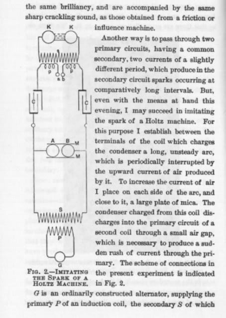
                            This is basically the AC circuit I've got setup now except I left out the
                            interrupting self blown spark gap in the middle which was just for the
                            Holt's/like machine demo.


                            Cheers

                            Comment


                            • Originally posted by mr.clean View Post
                              prob seen it already, this my most recent vid, since this it has improved with different primary and secondary wiring and adding FERRITE!!

                              but im looking for higher freq and im starting to think the ignition coils are not going to cut it. just when i get to 20khz, the power out of the circuit dives.

                              anyway like i said it has improved, but still in progress, just need some more lights now and igbt's

                              Don Smith Device Project Part 20c: Transient Spikes Powering Load From TOP, down - YouTube

                              am i correct in saying transient spikes?

                              also im planning on IGBTcap pulsing 60hz from the output caps to load,,, unless stepdown transformer is better?

                              any questions or comments or advice?
                              Those spikes kinda look like a cap discharge to me. Nice waveform. Cap pulsing at 60 Hz though the load sounds like a good idea to me.

                              Comment


                              • I would agree on the winding scheme, your definitely correct in that respect. I can see the CW-CCW working for a specific outcome other than what is needed here and primarily for canceling.

                                I see it as a pump if pulsed with DC, where it would have a specific polarity on the ends ( either pos or neg depending on the dominant pulse ). In this sense it would always draw from the ground if the center was earthed.

                                In any case, it's fun stuff indeed... what I would give to go back in time and spend several years working for free as his assistant....

                                Comment

                                Working...
                                X