Announcement

Collapse
No announcement yet.

Donald L. Smith

Collapse
X
 
  • Filter
  • Time
  • Show
Clear All
new posts

  • #76
    Hi Dragon, I was thinking I should take the hint you gave and go with only 20 turns
    (which is more like what Don used) haven't fully decided yet. I hope to have it
    up and running within about a week.

    Thanks for the compliment. I never used to like woodwork, but now i'm
    enjoying it.

    I also notice that in this picture.
    http://i48.servimg.com/u/f48/17/28/55/62/device10.jpg

    He has two 100 nF capacitors in parallel which if discharged at 20 Khz would be
    quite a lot of input power. The resonant frequency of that setup would seem to
    be about 250 - 260 Khz. Looks like about 17 or 18 turns on each side of the
    secondary.

    Comment


    • #77
      This drawing below from the document in the link (also below) shows clearly the
      way the secondary is connected to ground through a variable capacitor, which
      does kind of make sense.

      Document link. (Let me know if the link is faulty).
      https://skydrive.live.com/?cid=32A91...DCCE17F%211338


      Uploaded with ImageShack.us

      The question is. What size should the capacitor be ? Or what range of
      capacitance for a given device would be required ?

      Any thought's anyone ? I'm guessing the higher the frequency the smaller the cap.
      I can't wait to try it. I need a way to remove a variable amount of the fluid
      from a Layden jar to adjust the capacitance of the jar or something.

      Cheers

      Comment


      • #78
        This always looked like a basic solid state tesla coil to me. (with a fully adjustable joule thief style blocking oscillator) I'm not sure the benefit of the cap between ground but it will be interesting to see the effects of it if any, maybe a variation instead of the top load. I'd say start small and increase capacitance. Maybe a low filled layden jar and a turkey baster to fill it (remove from it ) slowly...

        Comment


        • #79
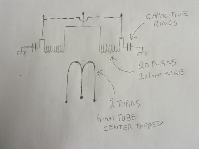
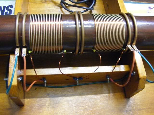
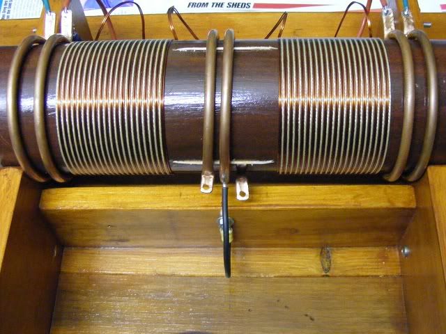
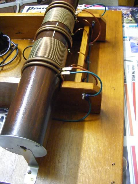
          Hi Guys, I wound my secondaries / L2. I center tapped the primary and connected
          a capacitor ring to the end of each side of L2 then another capacitor ring is
          connected to ground, this forms a variable capacitor to ground from the
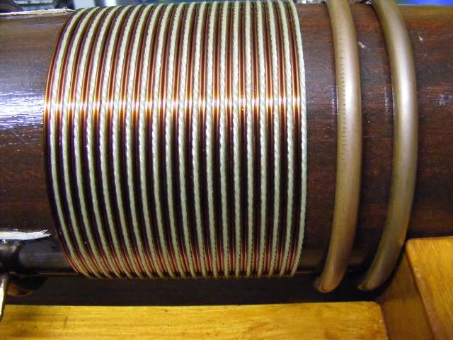
          + sides of L2, I still need to connect those ends together. I used 2 x 1 mm
          strands as one and made 20 turns with about 1 mm space between turns.
          I left room on the ends for "extra coils" when they are added the second
          capacitor ring will be disconnected form ground and the extra coil neg end
          connected to it then the end cap (retainer) will become the terminal capacitance.
          Funny thing, as I was winding the L2 coils with the thread between turns I
          thought to myself how it reminded me of binding a new runner or tip onto a
          fishing rod. How ironic.

          Basically I have this so far.


          Back side


          Front side


          Close up of winding


          Wide view


          Cheers all

          Comment


          • #80
            Lots of love went into that build ! Beautiful ! Looks like something from tesla's lab....

            Comment


            • #81
              Thanks for the kind comment Dragon. I hope it works as well as it looks.

              I think I've covered most of the bases so that it can be used in a number of
              different ways, ie the primary can be used with or without the center tap, the
              secondaries can be used as output and the extra coils ( I hope) when in place
              should increase the output. I'm about to put it onto the function generator,
              the natural resonant frequency will be too high for me to see the resonant point
              without caps, but I can hunt for harmonics, and study the coils character.


              Next step after that is to setup a primary circuit. Parallel resonance I think is the
              way to try first.

              I'm kinda glad I took your hint to keep the turn count down, thanks for that.

              The first part of my rod and reel is done, I've made the rod next part is the
              reel, then I will need a landing net or a gaff depending on what I hook up.

              Cheers

              Comment


              • #82
                Ok first preliminary report after some function generator testing.

                This is how I connected it up. I put the load only on one side and left the two
                L2 ends separated. The outer capacitor rings are joined and connected to
                ground by one wire (not two separate Earths like the drawing ) I noticed if
                I connect the two ends of the L2 together the scope trace flat-lines, which is
                what I expected to see , considering that the scope trace is completely
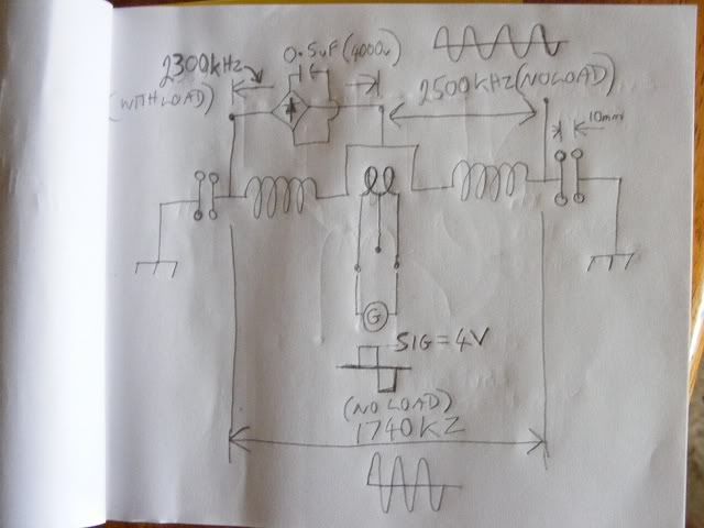
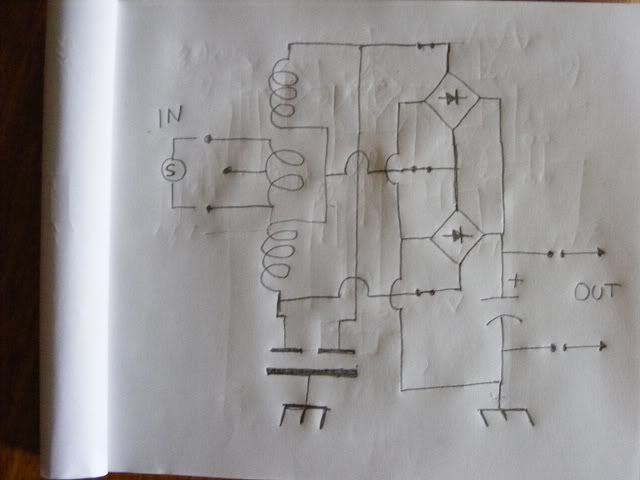
                free of any variation when they are connected I'm going to say they are
                completely cancelling each other. If the setup can charge a cap like that I will
                be very surprised.

                I'm thinking that the two ends of the L2 share a common capacitor plate so
                maybe that could be the trick.

                Anyway I get good resonance at 2.5 Mhz on each side unloaded with the cap
                rings about 20 mm apart. If I connect the FWBR with a 0.5 uF cap on the DC
                across one side the resonant frequency drops to 2.34 Mhz or so.
                My FG only works up to 3.5 Mhz, if there is a higher resonance I can't see it
                with the scope and FG I have, it looks good though, and lower than I expected.
                The resonant frequency across the entire L2 from end to end is 1.74 Mhz with no
                load capacitance, the voltage across both sides is double the voltage of one
                side. Both sides are the same frequency but out of phase so summed together
                in parallel they double the effective frequency. This is all done with the
                primary as close to the middle as I can get it, I haven't moved it yet. I'll try
                moving it soon. I also need to try using just one side of the primary with the
                function generator to see what happens.


                Basically I think this is what I'm looking at, and the right side of the sketch
                shows how I intend to load the output for one test. I'll try the negative Earth
                connection at the center tap instead of the DC negative as well to see what
                happens.


                There are a lot of different ways this could be connected and work in differing ways.

                Last edited by Farmhand; 02-26-2012, 07:27 AM.

                Comment


                • #83
                  Awesome build, like the capacitive rings something new, everyone should be trying new additions, mix it up, bifilar with one winding shorted, lots of idea's, should be getting my nst this week
                  dave
                  Half of the Answer is knowing the right Question

                  Comment


                  • #84
                    @Farmhand

                    Beautiful craftsmanship, looks like a museum piece.

                    Comment


                    • #85
                      Thanks guys, I hope I can keep it nice looking but I have a feeling that as I add stuff from here on it will start to look more like a shed device.

                      The rings are mainly there to couple some extra coils to the secondaries.

                      I haven't been able to achieve proper resonance yet.

                      Here's a video showing the waveform I had last night. The spark gap frequency was quite low, less than 10 Khz.

                      Not-Resonant Waveform.wmv - YouTube

                      One thing that did surprise me is that I was able to use the small neon power
                      supply at full power without it stopping at all. The problem is though that the
                      negative of the primary cap is not grounded I think it needs to be grounded.

                      Cheers

                      Comment


                      • #86
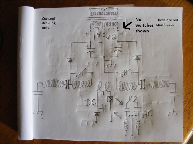
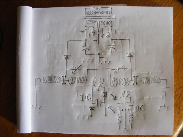
                        Ok I just drew one of the strangest looking drawings I think I've ever done.
                        I've done so many drawings on the previous pages it's becoming difficult to see
                        the lines. All the caps should be variable in some way. I think the AC circuit will
                        work well I've used that circuit before and still with other stuff. The outer
                        capacitors would have a substantial variable air gap. I think it would still work
                        without the "out riggers" or "extra coils" but rudimentary testings indicates an
                        advantage.


                        Just need to take the split positive in the caps and pulse it through two primaries
                        in opposite direction and alternately at 60 Hz directions like a regular power
                        inverter does.

                        Split the positive.

                        I don't think there is any symbolism in the sketch it just turned out funny lookin.

                        Cheers
                        Last edited by Farmhand; 02-27-2012, 05:06 AM.

                        Comment


                        • #87
                          Originally posted by Farmhand View Post
                          One thing that did surprise me is that I was able to use the small neon power supply at full power without it stopping at all. The problem is though that the negative of the primary cap is not grounded I think it needs to be grounded.

                          Cheers
                          The circuit will not operate properly without the primary cap being earthed, as this is where you are pumping magnetic current from.

                          I think you should ditch the coil later in favour of large caps, even though it is a masterpiece.

                          I would be very proud of that. You have excellent building skills!

                          Comment


                          • #88
                            Originally posted by Farmhand View Post
                            Ok I just drew one of the strangest looking drawings I think I've ever done.
                            I've done so many drawings on the previous pages it's becoming difficult to see
                            the lines. All the caps should be variable in some way. I think the AC circuit will
                            work well I've used that circuit before and still with other stuff. The outer
                            capacitors would have a substantial variable air gap. I think it would still work
                            without the "out riggers" or "extra coils" but rudimentary testings indicates an
                            advantage.


                            Just need to take the split positive in the caps and pulse it through two primaries
                            in opposite direction and alternately at 60 Hz directions like a regular power
                            inverter does.

                            Split the positive.

                            I don't think there is any symbolism in the sketch it just turned out funny lookin.

                            Cheers
                            Hey Farmhand

                            Does the current in secondary coil 1 and coil 2 actually go in opposite directions(CW & CCW)? Have you tested current direction? Thanks

                            Comment


                            • #89
                              Originally posted by nightwind View Post
                              Hey Farmhand

                              Does the current in secondary coil 1 and coil 2 actually go in opposite directions(CW & CCW)? Have you tested current direction? Thanks
                              Hi Nightwind, You mean the air core coils of the main device ? Yeah they are
                              both wound the same way as if from one coil, mine are both CCW wound so is
                              the primary. Because the L2 center tap is grounded one coil goes high while
                              the other goes low, by that I mean the center tap is grounded so it is 0 volts
                              the left coil goes high a positive voltage while the right coil goes low a
                              negative voltage (if they were connected they would cancel each other out).
                              Then because they are resonant they swing both ways so when the
                              left one goes low a negative voltage the right one goes high a positive.
                              However when they get half wave rectified only the positive portion charges
                              the cap (kind of) with only one coil this would halve the duty or (cap charge time)
                              but with two coils the duty of both halved is the same as the original 100% duty.

                              If the coils were wound opposite as in CW-CCW then the positive and
                              negative voltage of both coils would be at the same time, so when they are
                              both half wave rectified the duty is still reduced to 50% cap charging time.

                              Half wave rectifying retains voltage but halves the duty, full wave rectifying
                              halves the voltage but retains the duty. When we measure AC volts we only
                              measure one way from zero or one side same with frequency 60 Hz is 60 up
                              and 60 down. I think. If we full wave rectify a perfect AC square wave we fold
                              the voltage wave form in half horazontally and end up with a flat line of DC at
                              about the same voltage as the AC reading. With a sine wave we end up with
                              a series of bumps, if a sine wave is half wave rectified while the negative end
                              of the coil is grounded we end up with the AC voltage x 2 but only for half the
                              time. It gets complicated when the reference point is moved.

                              Cheers

                              P.S. I think I see what you mean now, the current through both sides of the
                              coil goes the same way at the same time (not opposite) I didn't say that it
                              went in opposite directions at the same time I don't think.
                              But because the coils are on opposite sides of the primary the
                              voltage induced is opposite and alternating at the same time. I did this with
                              two Tesla coils by connecting two identical Tesla coils secondary bottoms to
                              ground then connecting the primaries in series but reversed the connections
                              of one of the primaries and put the spark gap between them, they produced
                              opposite voltages as we would expect. If you could scope it at both ends
                              (two probes) at resonance you would see is a pair of crossed sine waves like
                              a DNA helix.

                              ..
                              Last edited by Farmhand; 02-27-2012, 03:58 AM.

                              Comment


                              • #90
                                Originally posted by Farmhand View Post
                                P.S. I think I see what you mean now, the current through both sides of the
                                coil goes the same way at the same time (not opposite) I didn't say that it
                                went in opposite directions at the same time I don't think.
                                But because the coils are on opposite sides of the primary the
                                voltage induced is opposite and alternating at the same time. I did this with
                                two Tesla coils by connecting two identical Tesla coils secondary bottoms to
                                ground then connecting the primaries in series but reversed the connections
                                of one of the primaries and put the spark gap between them, they produced
                                opposite voltages as we would expect. If you could scope it at both ends
                                (two probes) at resonance you would see is a pair of crossed sine waves like
                                a DNA helix.

                                ..
                                Thanks for clearing my fuzzy thinking. You didn't say opposite, but I thought that was what your arrows were implying.

                                Comment

                                Working...
                                X