Yes it is fun stuff indeed, I agree the CW-CCW setup can be very useful but if
a core was wanted there would need to be two separate one's "I think".
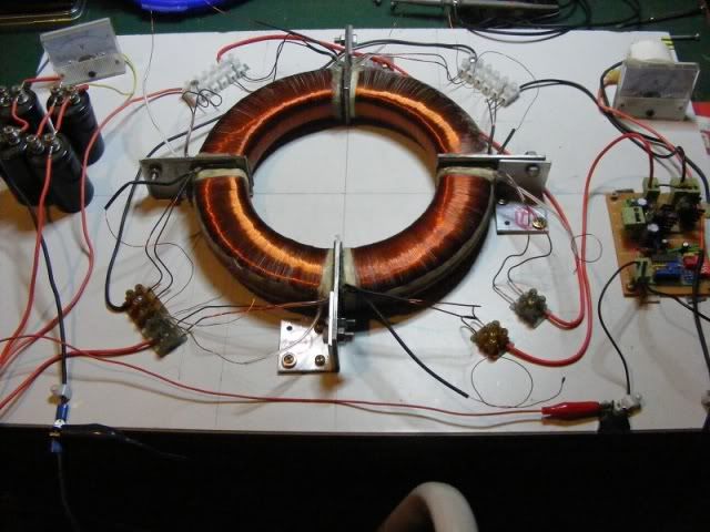
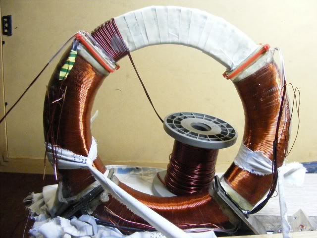
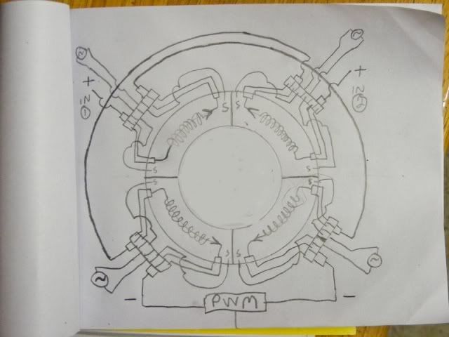
I wound a toroid once with four primaries all different ways ( two sets of two coils )
and one particular way I wound it with one CW and one CCW set I got zero
output. It does kinda depend what we want from the setup and how it's all
connected. I could be confused or wrong in some way, things will become
clearer as I do more testing.
I agree the ground is vital. Attaching a ground in the right place can make a big difference.
I do plan to make a DC primary circuit for the little setup, and I might have to, i'll just
rectify the 350 volts then use a DC resonant charging setup, I could make it a
dual one to pulse from each side to center at the same time which would
make the coils in phase and same polarity, but would need to remain air
cored. Or I could keep the primaries in series or put them in parallel. If a DC
primary circuit is used then it could be powered from a regular inverter or the
wall socket (maybe with a voltage doubler), (if the proper precautions are taken)
it must be made safe to run from the grid.
Lot's of different ways it can be used.
There is also the possibility of using these setups to make Stepped down AC
by applying alternating HV pulses to each end, the primary would output lower
voltage high current.
It's all very interesting, I've got several setups almost completed but still have
some months work before I can hope to begin the really interesting experiments.
If time travel was possible Nikola would have been in great danger and really
annoyed with all the visitors from the future asking him questions all day.
I would give a lot to do it too though.
Cheers
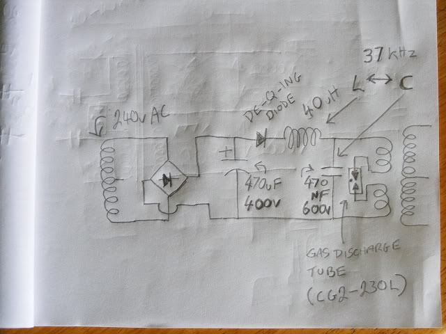
P.S. This could be what a DC primary circuit would look like. Something like
this should produce a resonant sine wave from the secondary if the frequency
of the primary circuit is correct for the secondary. I can't say if those values
for L and C are correct yet. There are also a few other different ways of doing it.
See the DC resonant charging section below.
DC Tesla Coil design
EDIT: This circuit did NOT work well when tested. Values are wrong.

2nd P.S. Maybe a sidac or even a triac or an SCR array could also work for
the switches or of course transistors, but I wanted to stay away from
transistors and complicated drivers.
..
a core was wanted there would need to be two separate one's "I think".
I wound a toroid once with four primaries all different ways ( two sets of two coils )
and one particular way I wound it with one CW and one CCW set I got zero
output. It does kinda depend what we want from the setup and how it's all
connected. I could be confused or wrong in some way, things will become
clearer as I do more testing.
I agree the ground is vital. Attaching a ground in the right place can make a big difference.
I do plan to make a DC primary circuit for the little setup, and I might have to, i'll just
rectify the 350 volts then use a DC resonant charging setup, I could make it a
dual one to pulse from each side to center at the same time which would
make the coils in phase and same polarity, but would need to remain air
cored. Or I could keep the primaries in series or put them in parallel. If a DC
primary circuit is used then it could be powered from a regular inverter or the
wall socket (maybe with a voltage doubler), (if the proper precautions are taken)
it must be made safe to run from the grid.
Lot's of different ways it can be used.
There is also the possibility of using these setups to make Stepped down AC
by applying alternating HV pulses to each end, the primary would output lower
voltage high current.
It's all very interesting, I've got several setups almost completed but still have
some months work before I can hope to begin the really interesting experiments.
If time travel was possible Nikola would have been in great danger and really
annoyed with all the visitors from the future asking him questions all day.

I would give a lot to do it too though.
Cheers
P.S. This could be what a DC primary circuit would look like. Something like
this should produce a resonant sine wave from the secondary if the frequency
of the primary circuit is correct for the secondary. I can't say if those values
for L and C are correct yet. There are also a few other different ways of doing it.
See the DC resonant charging section below.
DC Tesla Coil design
EDIT: This circuit did NOT work well when tested. Values are wrong.

2nd P.S. Maybe a sidac or even a triac or an SCR array could also work for
the switches or of course transistors, but I wanted to stay away from
transistors and complicated drivers.
..


Comment