Announcement

Collapse
No announcement yet.

Donald L. Smith

Collapse
X
 
  • Filter
  • Time
  • Show
Clear All
new posts

  • Yes it is fun stuff indeed, I agree the CW-CCW setup can be very useful but if
    a core was wanted there would need to be two separate one's "I think".
    I wound a toroid once with four primaries all different ways ( two sets of two coils )
    and one particular way I wound it with one CW and one CCW set I got zero
    output. It does kinda depend what we want from the setup and how it's all
    connected. I could be confused or wrong in some way, things will become
    clearer as I do more testing.

    I agree the ground is vital. Attaching a ground in the right place can make a big difference.

    I do plan to make a DC primary circuit for the little setup, and I might have to, i'll just
    rectify the 350 volts then use a DC resonant charging setup, I could make it a
    dual one to pulse from each side to center at the same time which would
    make the coils in phase and same polarity, but would need to remain air
    cored. Or I could keep the primaries in series or put them in parallel. If a DC
    primary circuit is used then it could be powered from a regular inverter or the
    wall socket (maybe with a voltage doubler), (if the proper precautions are taken)
    it must be made safe to run from the grid.
    Lot's of different ways it can be used.

    There is also the possibility of using these setups to make Stepped down AC
    by applying alternating HV pulses to each end, the primary would output lower
    voltage high current.

    It's all very interesting, I've got several setups almost completed but still have
    some months work before I can hope to begin the really interesting experiments.

    If time travel was possible Nikola would have been in great danger and really
    annoyed with all the visitors from the future asking him questions all day.
    I would give a lot to do it too though.

    Cheers

    P.S. This could be what a DC primary circuit would look like. Something like
    this should produce a resonant sine wave from the secondary if the frequency
    of the primary circuit is correct for the secondary. I can't say if those values
    for L and C are correct yet. There are also a few other different ways of doing it.
    See the DC resonant charging section below.
    DC Tesla Coil design

    EDIT: This circuit did NOT work well when tested. Values are wrong.
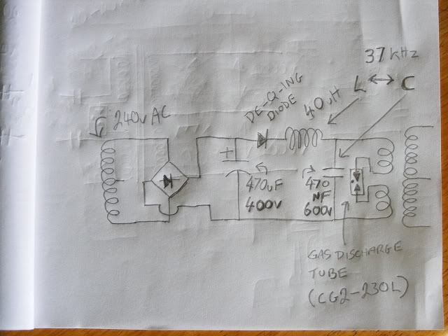

    2nd P.S. Maybe a sidac or even a triac or an SCR array could also work for
    the switches or of course transistors, but I wanted to stay away from
    transistors and complicated drivers.

    ..
    Last edited by Farmhand; 03-02-2012, 02:52 AM.

    Comment


    • That would work ! I've made a few driven from solar panels in series to provide 300 volts to the cap and a GDT as the spark gap. Another one I used for the power supply was simply a voltage multiplier in a similar set up plugged into an inverter. Basically tesla's circuit is a passive oscillator and simply needs an input voltage.

      It was kind of funny working with the solar powered coil, it was so bright outside I really couldn't tell if it was working or not - couldn't see the GDT flashing, FL tubes, LED's, plasma from the coil nothing... until I touched it - yee haaa --- yep it was working ! Couldn't help but laugh at myself. The second test I ran the wires from the solar panel inside to power the coil - much better results, visually.

      Gotta love this stuff...

      Comment


      • Yeah I'm having a lot of fun, unfortunately I was unable to make either of the
        last two circuits I posted work very well earlier, however I kept at it trying a few
        different DC circuits and worked out a few things, I've got the primaries in anti
        parallel now with 1.3 uf across the primaries and 3.7 uF discharged into them
        through two discharge tubes in series So about 3.7 uf at 440 volts or so is being
        dumped into them, it's making some fairly rapid very noisy sparks about 8 to 10 mm long,
        but the frequency and power looks low, I'll have to charge some caps with it and do
        some calculations to see what's what.

        The GDT's are getting very hot.

        Anyway I might have to resort to a core and transistors, I should use the wire
        along with some more to make a HV toroid transformer to go straight from 12v
        to 4000v, the one I have as the supply converter can do over 2000 volts if I
        connect all the coils in series and half wave rectify it.

        Cheers

        Here's a video clip of some sparks, first bit is three tubes then two.
        Coils test.wmv - YouTube

        ..
        Last edited by Farmhand; 03-01-2012, 02:21 AM.

        Comment


        • Good flick about cold fusion: Hulu - Outer Limits: Final Exam - Watch the full episode now.

          Comment


          • my ground connection...

            Originally posted by soundiceuk View Post
            Hi, I am currently running two of these ecore in anti parallel.

            FIAT PUNTO 0.9 1.1 1.2 IGNITION COIL PACK PAIR X2 SET | eBay

            The sparks are far superior than the oil filled single tower coils and I've tried 3 different brands.

            You will be impressed if you get them.

            The best bit about these coils is:

            a) the price
            b) most importantly the primaries are totally isolated from the secondaries.
            c) a good fat chunky earth can be fitted for the centre tap between the two coils twin towers.
            d) they can easily be mounted on a bracket.
            e) can be voltage, frequency, duty controlled.
            f) tested up to 100khz
            g) powerful spark for the money (I was quite shocked when I fired one up and saw the arcing between towers.)

            Downside

            Need HT leads for hassle free connection to towers.

            Mr Clean please can you advise on your earth connections and your ignition coil to connector block connections.

            Also where are all your earths connected to and are they using the same wire?


            I have found that using an electricians screwdriver is a good tool for testing whether you can touch part of the circuit with your hands. Just dont touch the bit you would if you were using 240/120v.

            Thats what I like about these ignition coils. The driver circuit can be so simple. Even use a signal gen on one transitor.

            Guess that means if a feedback coil can be included then the circuit will self oscillate into resonance provided L1 and L2 are matching.

            Also I believe L1 and L2 can be exactly the same and it will still work.

            The OU comes from the ionisation within the spark gap.

            Also please can anyone share some light on using a varistors / varactor and what would be suitable.
            Im using a 4mm (or something) 4 strand solid copper 20ft or so long wire going from litterally out the window, in the GROUND 12'' deep next to the house where rain can get to it

            (not sure if it matters, but i work in the basement. if you live in an appartment, then you gotta make due with plubming etc....

            but i recommend living on the ground where its natural and YOU are grounded too

            .. you could say the ground on my smith is a main branch that leads to several places

            **say you have a block terminal with 6 or 8 lead connections, the grnd wire goes on the far right,

            from that, Earth Ground touches the negative / center tap connecting to it solidly with no diodes for neg...

            (pos outter coil ends go thru 2 parallel forward MOT diodes on both sides)

            Same ground wire finally also connects to the battery's neg, or else you will be able to light a neon on the battry neg :0

            ...and even get shocked from the plastic on your battery LOL hehe, fun fun, but the circuit chips are only meant to handle 16 volts, not over 90volts

            so you'll end up killing your IC chips unless you earth ground the battery!
            (with heavy wire)

            i find no problem using the one wire for all grounding needs
            Last edited by mr.clean; 03-02-2012, 03:27 AM.
            In the beginner's mind, there are many possibilities.
            In the expert's mind there are few.
            -Shunryu Suzuki

            Comment


            • Yeah good ground is vital, I just recently put in a 6 foot stake where the
              ground down deep is always moist, it's a sump drain channel thing under there.

              Talking of HV supply transformers. I've decided to take another route, I'm
              going to wind up a toroid the same way as I wound the 240v supply
              transformer, but this one will have 4 x 2000 volt outputs that way I can use
              all four separately or make two sets of two 2000v - 0V - 2000v outputs or
              one 4000v - 0v - 4000v output. Going by the performance of the one I
              already made and use it should work well as long as I insulate the HV turns
              well enough. As I get towards the outer layers of the secondaries i'll use two
              then three layers of home made bees wax paper (thick stuff lots of wax). The
              biggest danger will be in the series connected secondaries in the layers
              closest to the primary so I will either use thick insulation there or wind the
              primaries next to the secondaries rather than under them, if I do that I will
              need to insulate the core well too.
              I've almost got the core laminae cut. The core will weigh the same as two
              secondaries.

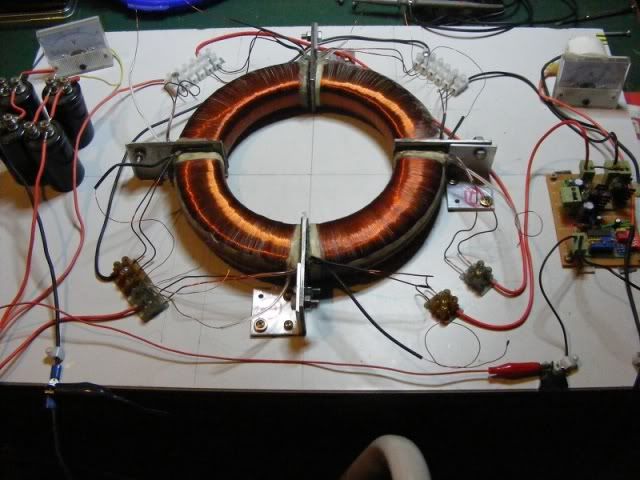
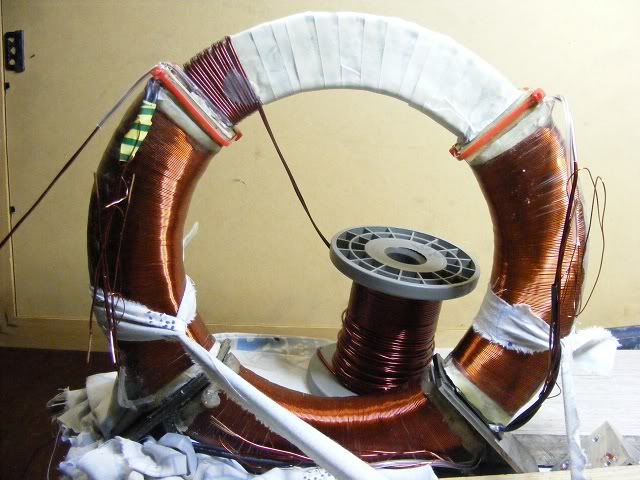
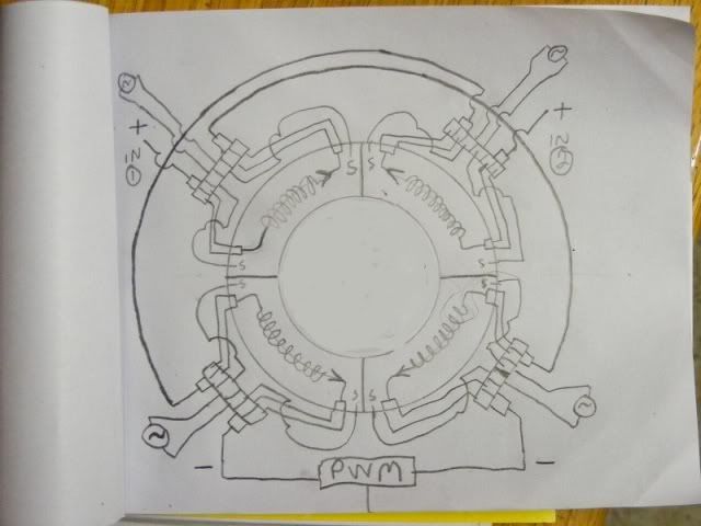
              Here's some pics of the 4 x 120v transformer. At resonance the 120 volts
              becomes more like 200 volts


              This drawing doesn't show the secondary windings just the outputs for ease
              of drawing.


              Cheers
              Last edited by Farmhand; 03-02-2012, 03:28 AM.

              Comment


              • I'm dismantling a big old TV for the parts, they have a lot of good stuff in them,
                I'm having trouble removing the deflection yolk, I don't want to break the tube.

                It was still working so everything should be good, There was some kind of thick
                heavy cable surrounding the tube for degaussing I think, maybe it would be a
                good type of cable for a primary in these setups, I can't see the actual wire in
                there yet.

                The TV had a power rating of 130 watts.

                Cheers

                Comment


                • Almost finished my new core, this one will be bolted together.

                  As far as an isolation/step down transformer goes I Think to be versatile a
                  transformer "like" the supply transformer I made above but in reverse as a
                  "converter" would work well. Two sets of two series connected transformers
                  with one transformer in each pair on opposite sides of the core. The way they
                  are connected means that if DC is pulsed into the two inputs alternately then
                  AC can be had from the outputs.

                  With 2000 turns of thin wire wound first on the core 1 in each quarter (4)
                  then 60 turns of thick wire over that for the primaries. This would give a transformation ratio of
                  33.3, per transformer, so with 8000 volts input there would be 4 volts per turn
                  on the primary and also the secondary so with 60 turns 240v would result. If
                  you wanted only 120 volts or so then if two thin wire primaries per pair are
                  put in series but the secondaries in parallel the result would be 120 volts,
                  both sets of transformers outputs can be put then in parallel also or used separately
                  or in series, so the available outputs would be 120v - 240v and 480 volts AC.

                  The one I use for a supply transformer has the thick wire wound first then the
                  thin wire on top, I think for step down the thin wire should be first then the
                  thick wire on top. For these high voltages I think we would need to insulate
                  the core with thick insulation and insulate between the layers of turns in the
                  thin wire coil, then insulate between the primary and secondary with very
                  good fairly thick insulation as well. I intend to encase the laminated core in
                  some insulator of some thickness.

                  Patent US382282 - NIKOLA TESLA - Google Patents

                  Cheers

                  Oh I almost forgot, I changed my mind and now I've made the core to be the
                  same weight as all the wire that will be in the transformer. ( this is for the 12
                  to 2000v x 4 transformer) not the step down.


                  ..
                  Last edited by Farmhand; 03-03-2012, 01:39 AM.

                  Comment


                  • Originally posted by Farmhand View Post
                    Almost finished my new core, this one will be bolted together.

                    As far as an isolation/step down transformer goes I Think to be versatile a
                    transformer "like" the supply transformer I made above but in reverse as a
                    "converter" would work well. Two sets of two series connected transformers
                    with one transformer in each pair on opposite sides of the core. The way they
                    are connected means that if DC is pulsed into the two inputs alternately then
                    AC can be had from the outputs.

                    With 2000 turns of thin wire wound first on the core 1 in each quarter (4)
                    then 60 turns of thick wire over that for the primaries. This would give a transformation ratio of
                    33.3, per transformer, so with 8000 volts input there would be 4 volts per turn
                    on the primary and also the secondary so with 60 turns 240v would result. If
                    you wanted only 120 volts or so then if two thin wire primaries per pair are
                    put in series but the secondaries in parallel the result would be 120 volts,
                    both sets of transformers outputs can be put then in parallel also or used separately
                    or in series, so the available outputs would be 120v - 240v and 480 volts AC.

                    The one I use for a supply transformer has the thick wire wound first then the
                    thin wire on top, I think for step down the thin wire should be first then the
                    thick wire on top. For these high voltages I think we would need to insulate
                    the core with thick insulation and insulate between the layers of turns in the
                    thin wire coil, then insulate between the primary and secondary with very
                    good fairly thick insulation as well. I intend to encase the laminated core in
                    some insulator of some thickness.

                    Patent US382282 - NIKOLA TESLA - Google Patents

                    Cheers

                    Oh I almost forgot, I changed my mind and now I've made the core to be the
                    same weight as all the wire that will be in the transformer. ( this is for the 12
                    to 2000v x 4 transformer) not the step down.


                    ..
                    oh cool man cant wait to see the finnished product!!
                    In the beginner's mind, there are many possibilities.
                    In the expert's mind there are few.
                    -Shunryu Suzuki

                    Comment


                    • coil direction

                      Ok you all are gonna laugh,

                      but can i get a confirmation on primary and secondary winding directions? LOL

                      Just watching a Don vid i found, and now im back to wondering about the fundamentals.

                      He said in his briefcase model he targeted...wait for it.... !200 Mhz!

                      And one thing i read was that a coil will always ring at its natural freq, regardless of the driver freq, so not only would that imply that CHOSEN freq is truely dependant on WHAT WIRE lengths we are using, as well as ratio.

                      and the double coil board I Saw him Point to the top half and said voltage, then the bottom half and said amperage.

                      ...The windings cw cw

                      But does the direction of the primary also matter? somewhere i read that it changes the polarity, but cant tell on my scope
                      Last edited by mr.clean; 03-08-2012, 08:33 PM.
                      In the beginner's mind, there are many possibilities.
                      In the expert's mind there are few.
                      -Shunryu Suzuki

                      Comment


                      • Yeah I heard him say 200 Mhz too, but the coil won't ring at it's natural
                        frequency after a cap is added to it. To make a resonant coil ring with a lower
                        frequency input it can be done by hitting a lower harmonic with normal pulses
                        or it can be done with big sudden inputs of energy to a tank which resonates
                        at the same frequency as the secondary with tuning cap or without one if none is
                        going to be used. The primary can have a cap to make it resonant at the
                        desired frequency or if the sudden disharges through it are at a harmonic of
                        the desired frequency the primary will usually ring long enough without a
                        tuning cap, the effectiveness of that can depend on the coupling with the
                        secondary by the secondary reacting on the primary with the primary or
                        against it, "I think".

                        The primary capacitor will only fire when charged and the potential difference
                        at the spark gap is enough so the spark gap should self tune to the
                        oscillations because of that. If the primary oscillation shows a high voltage at
                        the spark gap at the same time as the tank cap is charge the tank cap won't
                        be able to fire the spark gap until the primary oscillation causes the voltage
                        on the primary side of the spark gap to be low enough to allow the spark gap
                        to fire. That is with a positive line spark gap a negative line spark gap would
                        be opposite but the same effect is had.

                        The spark gap likely won't ever fire at the same
                        frequency as the NST.

                        The primary winding direction in my opinion should be the same as the other
                        two coils the L2.

                        I won't be laughing at anyone I don't know enough to be that way inclined.
                        A big grin is all I can muster.

                        Cheers

                        Comment


                        • trace at 1Mhz

                          ...When i zoom in to 1u/Sec div, on L2,

                          on spark firing, i get a very clear 3 wave whale-like (build and fall) even form which is steady and only changes is magnitude, NOT freq, when i adjust spark gap and/or freq dials !!

                          So, im going back to the pdf notes, and i know there are many, but is there a simple program to tell me freq and wire length?

                          if the upload works, then the first is the load wave form with no ferrite, second is ferrite just barely inside L1, the third is the ferrite 3cm inside, which was optimal, and anything more or less output is less

                          So it is reading a short 1 Mhz wave, spaced out to the spark-gap firing frequency.

                          the primary wave is not even visible at 1uS, and its freq was not the same as the L2 wave (if im seeing this right)

                          But when i zoom out to .2mS, the primary rising wave re-appears in range, can someone clarify the freq issue between coils, i dont see any trace at 1uS in L1, but its there in L2
                          Last edited by mr.clean; 02-14-2013, 02:46 AM.
                          In the beginner's mind, there are many possibilities.
                          In the expert's mind there are few.
                          -Shunryu Suzuki

                          Comment


                          • awesomw man!

                            Originally posted by Farmhand View Post
                            Yeah I heard him say 200 Mhz too, but the coil won't ring at it's natural
                            frequency after a cap is added to it. To make a resonant coil ring with a lower
                            frequency input it can be done by hitting a lower harmonic with normal pulses
                            or it can be done with big sudden inputs of energy to a tank which resonates
                            at the same frequency as the secondary with tuning cap or without one if none is
                            going to be used. The primary can have a cap to make it resonant at the
                            desired frequency or if the sudden disharges through it are at a harmonic of
                            the desired frequency the primary will usually ring long enough without a
                            tuning cap, the effectiveness of that can depend on the coupling with the
                            secondary by the secondary reacting on the primary with the primary or
                            against it, "I think".

                            The primary capacitor will only fire when charged and the potential difference
                            at the spark gap is enough so the spark gap should self tune to the
                            oscillations because of that. If the primary oscillation shows a high voltage at
                            the spark gap at the same time as the tank cap is charge the tank cap won't
                            be able to fire the spark gap until the primary oscillation causes the voltage
                            on the primary side of the spark gap to be low enough to allow the spark gap
                            to fire. That is with a positive line spark gap a negative line spark gap would
                            be opposite but the same effect is had.

                            The spark gap likely won't ever fire at the same
                            frequency as the NST.

                            The primary winding direction in my opinion should be the same as the other
                            two coils the L2.

                            I won't be laughing at anyone I don't know enough to be that way inclined.
                            A big grin is all I can muster.

                            Cheers
                            Hehe ok man, thats great!!

                            Oh and i posted this in the other thread, but here...

                            had some good results last nite, so i made another vid. Increase in output with same input as previous vid...

                            im using 80 turn B&W's model# 2408TL both cw cw with center tap.

                            With the right valued, you WILL get output from both ends of the coil

                            and 10 turn primary, this time with series LC and parallel spark (like Dynatron and Destine2012

                            from the length of the 80 turn b&w, i calculates to a 15.66 Mhz natural freq
                            (62.8 ft of inductor), and the 1/4 wave length for that is 15.70 ft for L1, but my L1 is slightly shorter, need more 8 gauge wire.

                            the L2 low capacitance caps are parallel to the outer ends, (like Dynatron and Destine2012)before the diodes. rather than center tap and outer.

                            Don Smith Device Project Part 21: New coils CW CW and Primary Series LC Tank, Overall Improvement ? - YouTube

                            **Ok so remember my vid 20b (or something) i showed how 12 volts will light 1 lite, drawing 100mA per bulb??

                            then gets dimmer as more bulbs are added in series...

                            So with 5 bulbs, there is a current draw of 100ma X 5, but not enough voltage to push thru all 5, everyones with me?

                            Therefore 6 watts @ 12 volts will not light the 5 bulbs...right??

                            Here I am seeing 5 bulbs lit at .5 Amp X 12volts .....but acting as if it were 60 volts at .5 amps...right?

                            ****So is this 6 watts making 30 watts???*** COP 5 ?

                            And btw, voltage is so high now that it blows right thru ALL my caps, in series even!!

                            Plus, going higher than .5 amps input, i believe it is even more efficient, we will see
                            Last edited by mr.clean; 03-05-2012, 08:33 PM.
                            In the beginner's mind, there are many possibilities.
                            In the expert's mind there are few.
                            -Shunryu Suzuki

                            Comment


                            • opposite

                              Hi Farmhand,

                              I have a comment on the circuit in your posting http://www.energeticforum.com/188095-post4025.html
                              I am using this thread, as I don't want to interfere with the discussion in the other.

                              Originally posted by Farmhand View Post
                              ...and the transformers I used were identical CCW.
                              Yet, if you look at the drawing in ALL Tesla's (wireless) transmitter and magnify transmitter patent(s) - starting from "645,576 - System of Transmission of Electrical Energy" - you will see, that the input transformer's primary and secondary are wound opposite to the output transformers winding.

                              I just noticed that (while thinking about directionality in general), and wanted to mention it.

                              The attached image is of patent 649,621 - Apparatus for Transmission of Electrical Energy.
                              And no, nothing of the winding direction is in the text, only in the drawings.
                              Attached Files
                              Last edited by marxist; 04-12-2012, 01:54 PM. Reason: added patent numbers

                              Comment


                              • Hi marxist, Yes the patent I think you refer to is this one.

                                Patent US649621 - NIKOLA TESLA - Google Patents

                                I don't know of any other patents where it appears the transformers are
                                wound oppositely.
                                However looks can be deceiving, they are flat spiral coils, so they cannot be
                                wound oppositely. If you take two flat spiral coils "oppositely" wound, and
                                then flip one over they are then wound the same. Or if you take them from
                                the horizontal plane and then place them into the vertical plane as I think as
                                Tesla shows his was used they would be the same. It's not really two
                                dimentional but it has no "turn height". The circumference is constantly
                                diminishing too but that's another matter. Actually it's turn height is in the
                                same plane as the diameter. A solenoid is different.

                                That patent above is for atmospheric transmission as well, I think it requires at least
                                a line of sight between the air terminals. Whereas the ground transmission
                                system does not require that, as in the patents below. The coils I used are
                                modeled very loosely on the first patent below.

                                Patent US1119732 - ELECTRICAL ENERGY - Google Patents

                                Patent US787412 - NIKOLA TESLA - Google Patents

                                Anyway the effect of opposite winding the transformers I think is minimal and
                                only when used close together. The effect is only that opposite wound coils when
                                next to each other rather than being opposite polarity they are the same.
                                Which is why opposite wound coils might work better when they are close
                                together, when they are apart it doesn't matter.

                                I was mainly giving feedback on the switching circuit, and reporting the result
                                i got with my particular setup. I already had the Tesla type coils so I used
                                them for the test. I'm stoked that I finally got a self oscillating circuit to work
                                and as far as lighting up fluro's goes it's great. But I got much better results
                                when transmitting energy by "ground wire" further than a few meters when I
                                used an IC oscillator I could control and keep the frequency constant and
                                tune with variable inductance and capacitance.

                                About the opposite wound flat spiral coils and the patent, I don't see that he
                                says the coils should be wound opposite, but I did skim read the patent I may
                                have missed it, though I don't remember reading it last time either.

                                Cheers
                                Last edited by Farmhand; 04-12-2012, 12:41 PM.

                                Comment

                                Working...
                                X