 Tweet
Tweet
VIRTUAL PHOTON POWER CONVERTER (more detail:
Power Converter)
EMF EXPLANATION
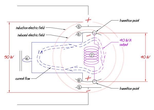
For any single phase power transformer attached to the grid the primary winding has an electro-magnetic footprint. Part of this footprint is that the primary is in an electric field. Out of this electric field across the primary there is an electron flow through the primary winding creating a magnetic field. Energy from the grid that creates these electric and magnetic fields is translated through the fields by the secondary winding and then to the house or whatever. The secondary gets its energy from these fields.
Both the electric and magnetic fields fluctuate with the frequency of the grid. The electric field component stays the same according to frequency and for the most part is constant; voltage is constant. However, the magnetic field � electron flow � varies with power draw and is what translates the energy transfer. The current flow � magnetic field -- in the primary is directly proportional to the energy � VA -- being extracted from the transformer.
And, for any single phase power transformer the voltage field and the electron source/magnetic field come from the same energy source.
With the VPPC there are two energy sources. The electric field energy source suspends the primary winding (7) in a closed circuit electric field. With the electric field circuit, being a capacitive circuit, the current is the migration current between capacitor plates. This current is going through the primary (7) as it is polarized and suspended in the electric field.
The current energy source feeds into this electric field suspended coil through C1 and provides the magnetic field component for the primary. When the electric field and current flow mix in C1, the primary (7) is energized by an electron flow coming out of one high voltage(HV)potential across the transformer, through the transformer, towards and into the other HV potential on the other side of the transformer. This provides the magnetic component of the primary winding�s electro-magnetic footprint.
The secondary (8) is energized by both of these field components mixing in the primary (7). From these fields, the secondary draws its energy or power. So, essentially what this device does is it would give a line transformer primary the same electro-magnetic field footprint and therefore VA capabilities of being on the grid; when it�s not on the grid.
Since the HV circuit is a coil capacitor circuit, its power draw would be directly related to the capacitance and have a relatively low VA. In addition, normally the voltage on a capacitor is 90 degrees out of phase with the current in the coil across it. This necessitates a device (11) that keeps the voltage on the capacitor C1 and therefore on the primary in phase with the current in (4).
Depending on the voltage applied, the major VA consumption with this device would be the current source generating the magnetic fields in the electric field suspended primary winding. In addition this power consumption would be inversely proportional to the electric field potential � voltage � across the coil. For any transformer and a given power draw, the higher the voltage field across the primary, the less the current in the magnetic field circuit.
In summary, this device would give a single phase line transformer the electro-magnetic field footprint and VA capabilities of when it�s attached to the grid with a VA input that is a fraction of its VA output.
Energy is pulled out of the virtual photon quantum state to do this.
VIRTUAL PHOTON EXPLANATION
Physics, in the field of quantum electrodynamics, hypothesizes the existence of virtual photons. These are hypothetical photons with an infinite amount of potential energy. This theory is used to explain the non-conservative nature of two and a half of the four basic physics interactions. The virtual photon explanation is used to explain the amount of physical force that can occur for a relatively small amount of electrical work with Coulomb�s Law. The virtual photon theory is also used to explain the available forces in gravity and weak nuclear as well.
This device is an attempt to convert the infinite power potential of a virtual photon into an actual electromagnetic power drive circuit � electrical energy. The idea is an attempt to amplify electrical power through the use of a VPR (Virtual Photon Reference).
A primary object of the VPPC is to provide a power amplification circuit utilizing quantum principals in order to harness and extract additional power from a quantum state. Another object of the VPPC is to provide a power amplification circuit utilizing capacitors and transformers in order to harness power from virtual photons in a quantum electric field. Yet another object of the VPPC is to provide a power amplification circuit utilizing a phased electric field and magnetic field in order to produce a condition useful in producing and harnessing virtual photons.
Assuming electric fields can manifest a virtual photon reference � VPR -- and assuming electric fields within capacitors have a VPR, then within the circuit of the present invention having a pair of high voltage capacitors connected in series there would be VPR within each capacitor, (b) and (c) of Figure 2. The circuit across the two capacitors is another capacitor � VPR (a) � and this is the electric field that energizes the entire mixing capacitor plate/winding/plate/winding assembly. The electric field induced on the mixing capacitor plate/winding/plate/winding assembly electrically polarizes that assembly thus creating a fourth VPR, (d). In summary a VPR is suspended inside another VPR with two VPRs connecting the two. This event occurs when any two capacitors are in series and in close proximity. In this circuit, within VPR (d), is an electrical closed circuit magnetic field device � plate/winding/plate/winding assembly � suspended between the electric fields. This device has one end of a pair of transformer windings going through one VPR while the other ends of the pair are connected through another VPR � (b) and (c) -- and this magnetic field assembly is contained in VPR (d).
The goal behind this is to put electrical energy into a VPR system, tap into the infinite potential energy of a VPR,
and bring some of this infinite potential energy into actuality with it as it comes out of the VPR system as electrical energy � a power amplifier. This system is trying to do this by feeding the input power into a closed high voltage capacitance system.
Going on the assumption that the stronger the electric fields the more the VPR involvement, as evidenced in Coulomb�s Law, then the higher the voltage across C1a � 5 to C1b � 5 the more power this device should have.
The concept behind the VPPC circuit is more than the VPPC application itself. The VPPC circuit suspends a closed circuit in an electric field and magnetically exciting that closed circuit while using the mix of the two fields.
CONCLUSION
The point is; once it is recognized that for any electro-magnetic field device, using separate energy sources, the combination of the electric field and the magnetic field (and their relationship) can be customized in terms of relative field strength, phase and/or field polarity, and/or spatial relationship. From my limited perspective, this concept opens a whole new field of study (pardon the pun) and can present a broad spectrum of new applications. It�s �pick a card, any card� time.
One end of this application spectrum may be the VPPC with its infinite potential energy of a virtual photon. At the other end of the spectrum, reversing the electric field polarity, the basic coil/plate/coil/plate VPPC circuit can serve as an electric field modulator or switch. Somewhere in that spectrum is the potential for a RF antenna whose induction field matches its radiation field or the electric field transformer motor (Electric Field Transformer). Throw in the application of the three vectors to EMF, shaping, mono-polarity fields, and standing waves, then this spectrum could get real sci-fi with electromagnetic force fields and propulsion.
Power Converter)
EMF EXPLANATION
For any single phase power transformer attached to the grid the primary winding has an electro-magnetic footprint. Part of this footprint is that the primary is in an electric field. Out of this electric field across the primary there is an electron flow through the primary winding creating a magnetic field. Energy from the grid that creates these electric and magnetic fields is translated through the fields by the secondary winding and then to the house or whatever. The secondary gets its energy from these fields.
Both the electric and magnetic fields fluctuate with the frequency of the grid. The electric field component stays the same according to frequency and for the most part is constant; voltage is constant. However, the magnetic field � electron flow � varies with power draw and is what translates the energy transfer. The current flow � magnetic field -- in the primary is directly proportional to the energy � VA -- being extracted from the transformer.
And, for any single phase power transformer the voltage field and the electron source/magnetic field come from the same energy source.
With the VPPC there are two energy sources. The electric field energy source suspends the primary winding (7) in a closed circuit electric field. With the electric field circuit, being a capacitive circuit, the current is the migration current between capacitor plates. This current is going through the primary (7) as it is polarized and suspended in the electric field.
The current energy source feeds into this electric field suspended coil through C1 and provides the magnetic field component for the primary. When the electric field and current flow mix in C1, the primary (7) is energized by an electron flow coming out of one high voltage(HV)potential across the transformer, through the transformer, towards and into the other HV potential on the other side of the transformer. This provides the magnetic component of the primary winding�s electro-magnetic footprint.
The secondary (8) is energized by both of these field components mixing in the primary (7). From these fields, the secondary draws its energy or power. So, essentially what this device does is it would give a line transformer primary the same electro-magnetic field footprint and therefore VA capabilities of being on the grid; when it�s not on the grid.
Since the HV circuit is a coil capacitor circuit, its power draw would be directly related to the capacitance and have a relatively low VA. In addition, normally the voltage on a capacitor is 90 degrees out of phase with the current in the coil across it. This necessitates a device (11) that keeps the voltage on the capacitor C1 and therefore on the primary in phase with the current in (4).
Depending on the voltage applied, the major VA consumption with this device would be the current source generating the magnetic fields in the electric field suspended primary winding. In addition this power consumption would be inversely proportional to the electric field potential � voltage � across the coil. For any transformer and a given power draw, the higher the voltage field across the primary, the less the current in the magnetic field circuit.
In summary, this device would give a single phase line transformer the electro-magnetic field footprint and VA capabilities of when it�s attached to the grid with a VA input that is a fraction of its VA output.
Energy is pulled out of the virtual photon quantum state to do this.
VIRTUAL PHOTON EXPLANATION
Physics, in the field of quantum electrodynamics, hypothesizes the existence of virtual photons. These are hypothetical photons with an infinite amount of potential energy. This theory is used to explain the non-conservative nature of two and a half of the four basic physics interactions. The virtual photon explanation is used to explain the amount of physical force that can occur for a relatively small amount of electrical work with Coulomb�s Law. The virtual photon theory is also used to explain the available forces in gravity and weak nuclear as well.
This device is an attempt to convert the infinite power potential of a virtual photon into an actual electromagnetic power drive circuit � electrical energy. The idea is an attempt to amplify electrical power through the use of a VPR (Virtual Photon Reference).
A primary object of the VPPC is to provide a power amplification circuit utilizing quantum principals in order to harness and extract additional power from a quantum state. Another object of the VPPC is to provide a power amplification circuit utilizing capacitors and transformers in order to harness power from virtual photons in a quantum electric field. Yet another object of the VPPC is to provide a power amplification circuit utilizing a phased electric field and magnetic field in order to produce a condition useful in producing and harnessing virtual photons.
Assuming electric fields can manifest a virtual photon reference � VPR -- and assuming electric fields within capacitors have a VPR, then within the circuit of the present invention having a pair of high voltage capacitors connected in series there would be VPR within each capacitor, (b) and (c) of Figure 2. The circuit across the two capacitors is another capacitor � VPR (a) � and this is the electric field that energizes the entire mixing capacitor plate/winding/plate/winding assembly. The electric field induced on the mixing capacitor plate/winding/plate/winding assembly electrically polarizes that assembly thus creating a fourth VPR, (d). In summary a VPR is suspended inside another VPR with two VPRs connecting the two. This event occurs when any two capacitors are in series and in close proximity. In this circuit, within VPR (d), is an electrical closed circuit magnetic field device � plate/winding/plate/winding assembly � suspended between the electric fields. This device has one end of a pair of transformer windings going through one VPR while the other ends of the pair are connected through another VPR � (b) and (c) -- and this magnetic field assembly is contained in VPR (d).
The goal behind this is to put electrical energy into a VPR system, tap into the infinite potential energy of a VPR,
and bring some of this infinite potential energy into actuality with it as it comes out of the VPR system as electrical energy � a power amplifier. This system is trying to do this by feeding the input power into a closed high voltage capacitance system.
Going on the assumption that the stronger the electric fields the more the VPR involvement, as evidenced in Coulomb�s Law, then the higher the voltage across C1a � 5 to C1b � 5 the more power this device should have.
The concept behind the VPPC circuit is more than the VPPC application itself. The VPPC circuit suspends a closed circuit in an electric field and magnetically exciting that closed circuit while using the mix of the two fields.
CONCLUSION
The point is; once it is recognized that for any electro-magnetic field device, using separate energy sources, the combination of the electric field and the magnetic field (and their relationship) can be customized in terms of relative field strength, phase and/or field polarity, and/or spatial relationship. From my limited perspective, this concept opens a whole new field of study (pardon the pun) and can present a broad spectrum of new applications. It�s �pick a card, any card� time.
One end of this application spectrum may be the VPPC with its infinite potential energy of a virtual photon. At the other end of the spectrum, reversing the electric field polarity, the basic coil/plate/coil/plate VPPC circuit can serve as an electric field modulator or switch. Somewhere in that spectrum is the potential for a RF antenna whose induction field matches its radiation field or the electric field transformer motor (Electric Field Transformer). Throw in the application of the three vectors to EMF, shaping, mono-polarity fields, and standing waves, then this spectrum could get real sci-fi with electromagnetic force fields and propulsion.


Comment