Announcement

Collapse
No announcement yet.

Open Source Project for Tesla/Jackson Wireless Transmission

Collapse
X
 
  • Filter
  • Time
  • Show
Clear All
new posts

  • #31
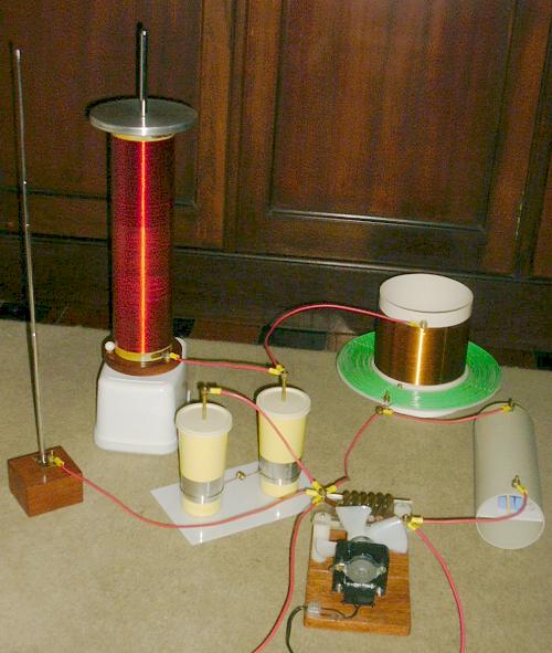
    I see so the secondary is wrapped around the "fence like structure" right next to him and the primary is wrapped around the bigger but lower fence like structure in the backround ?

    I remember Eric Dollard said that winding the coils on a solid form is bad and a slat type structure should be used. And that the secondary should be as round as it is high. Hmmm cool.

    I will just wind another tower type coil the same as what I have and install some sphere's or toroid dome's while I read some more of this thread. I'll also try to mount the primary on a frame.

    Then I will try some things wirelessly.

    Cheers

    Comment


    • #32
      Oh ok now I see, the bottom part of the secondary is quite close to the primary. Wow that is different. Ahah.

      Comment


      • #33
        Well all plans are now revised, I have 4 x 120 feet lengths of 0.5mm wire.

        If I build frames kind of like in the picture but maybe solid for ease, then wind a two diameter/stage secondary like in the picture.

        But how will I determin the diameter of the primary and the large part of the secondary and how many small turns on the secondary ? I have a PIC to pulse at Mhz frequencies but I'll have to work out how to use it later I can use a spark gap now though.

        What frequency range will I need to use about, on a small setup for experiment ? I guess the longer the secondary the lower the frequency. But the calculations baffle me.

        Cheers

        Comment


        • #34
          did a small research on Tesla Transmission Magnifier, i found this:

          Below I describe what I have obtained working on the ideas that I found in the papers [1] and [2]. A set of formulas that allow, at least ideally (losses ignored, lumped model assumed as valid), the design of a perfect Tesla magnifier circuit, or triple resonance transformer, are presented.

          A Tesla magnifier is a variation of the Tesla transformer where the resonator is separated from the secondary coil. The main objective of the modification is to obtain fast energy transfer without excessive voltage stress in the transformer. The magnifier is here modeled by the lumped circuit shown below:


          By April 2003 I started experiments with a 6th-order Tesla magnifier, in an attempt to verify if the design method developed for triple resonance networks can be also useful for an application intended for the production of sparks and streamers, a variation of the classical Tesla coil


          A 6th-order Tesla Magnifier


          Designing a Tesla magnifier

          It looks like i answered my own question, don't you think?

          I see so the secondary is wrapped around the "fence like structure" right next to him and the primary is wrapped around the bigger but lower fence like structure in the backround ?

          I remember Eric Dollard said that winding the coils on a solid form is bad and a slat type structure should be used. And that the secondary should be as round as it is high. Hmmm cool.

          I will just wind another tower type coil the same as what I have and install some sphere's or toroid dome's while I read some more of this thread. I'll also try to mount the primary on a frame.

          Then I will try some things wirelessly.
          Farmhand, correct me if I'm not wrong but isn't that actually the principle of fractal, having a larger primary within which a smaller secondary is placed and so on....?

          I am saying this based on this post http://www.energeticforum.com/142311-post45.html ,(second half of post)

          I found this document, which i think is authored by Nicolas Tesla, I have uploaded it, so as you can have access to it

          Quite different conditions exist in my system in which the electromagnetic waves or radiations are designedly minimized. the connection of one of, the terminals of the transmitting circuit to the ground having, itself, the effect of reducing the energy of these radiations to about one-half, Under observance of 'proper rules and artifices the distance is of little or no consequence, and by skillful application of the principle of "individualization," repeatedly referred to the messages may be rendered both non-interfering and non-interferable. This invention, which I have described in technical publications, attempts to imitate, in a very crude way, the nervous system in the human body

          ...I conclude that the invention wilt permit the simultaneous transmission of several millions of separately distinguishable messages through the earth, which, strangely enough, is in this respect much superior to an artificial conductor
          .' Nicolas Tesla
          a while back i wrote this in a post on fractal antenna:

          I think that Tesla was the first to realize the Constructal/ fractal properties of Nature and was able to use that in order to make a fractal antenna out of whatever he wished and to tap into the scalar waves as well. Some think that Scalar waves travel at the speed of thought (which is of course instantaneous), maybe it is and if so, then Scalar waves and "telepathy wave" are likely to be one and the same. Which leads me back to the title of this thread: The Brain is an Advanced Fractal Antenna.
          Frontiers | Fractals in the nervous system: conceptual implications for theoretical neuroscience | Frontiers in Fractal Physiology

          This essay is presented with two principal objectives in mind: first, to document the prevalence of fractals at all levels of the nervous system, giving credence to the notion of their functional relevance; and second, to draw attention to the as yet still unresolved issues of the detailed relationships among power-law scaling, self-similarity, and self-organized criticality. As regards criticality, I will document that it has become a pivotal reference point in Neurodynamics. Furthermore, I will emphasize the not yet fully appreciated significance of allometric control processes. For dynamic fractals, I will assemble reasons for attributing to them the capacity to adapt task execution to contextual changes across a range of scales. The final Section consists of general reflections on the implications of the reviewed data, and identifies what appear to be issues of fundamental importance for future research in the rapidly evolving topic of this review.
          Last edited by MonsieurM; 06-07-2011, 11:48 AM.
          Signs and symbols rule the world, not words nor laws.” -Confucius.

          Comment


          • #35
            OK I have some stuff together, I have PVC cylinders to wind th coils on, I have 100mm x 115mm diameter for the primary and secondary coil's "C" and "A" and 55mm x 505 mm for the third coil "B". I also have aluminium discs 100mm diameter and flexable vacuum cleaner hose to fashion some toroidal type top thingy's, I'll cover the flexable hose with aluminum foil.

            http://wv0v9q.bay.livefilestore.com/...001.JPG?psid=1

            I have 1mm wire for the primary and 0.5mm wire for the secondary and third coils. I will wind the primary directly onto the bottom part of the secondary with only some insulation between. The secondary will take up between the line's on the big cylinder but the primary only a part of that at the bottom. and the third coil starts at the bottom line (top line a mistake) and go's as far as I think. the rest can be covered in aluminium as the cylindrical conductor in the patent up to the top toroid.

            I am hopeless with figure's so I am going with intuition for the number of winds and I can adjust them later or rewind. I will build two exactly the same at the same time.

            Cheers

            Comment


            • #36
              You dont need to know all the math and such, but it will really help to just use tools available online. Here are some sites that will do the calculations for you.

              DeepFriedNeon - Tesla Coils

              OLTC Calculator

              Javascript Tesla Coil Designer

              LC Resonance Frequency Calculator at WhatCircuits.com

              There is a lot of hearsay about the magnifyer design, most of it I think is all junk made by folks that have never built or tested it. You dont need to use that exact design to get results, but i do prefer the helical coils. A simple design for low voltage testing would be making a setup like solid state tesla coilers like to make. Just one secondary and a closely coupled helical coil primary. Here are some examples.


              I would encourage you to test all the different coils and setups and draw your own conclusions and try to learn why he settled on the magnifyer design. After testing many coils I believe i have a good idea of why its designed as it is but i still have more testing to do myself.

              Comment


              • #37
                Take also a look in my double resonance simulator TeslaSim, that allows experiments with Tesla coil circuits, and also inversion of Laplace transforms. The program MagSim, that designs systems based on the formulas presented here, and can generate Laplace transforms to be used in the TeslaSim program, is also available. See also the program Mrn6.

                Designing a Tesla magnifier

                A transformerless Tesla coil

                This circuit has several potential advantages over a simpler directly coupled Tesla coil: Faster energy transfer from C1 to the distributed terminal capacitance C3, what results in smaller losses, greater efficiency, and insensitivity to tuning precision. The wider notches in the primary waveforms tend to cause fast quenching of the spark gap, at the first notch, trapping all the energy in the high-voltage part of the circuit. The design is restricted by the absence of the extra degree of freedom allowed by a transformer in the classic magnifier circuit, with the maximum voltage gain being forced by the ratios among the resonance frequencies, but the transformerless construction is simpler.
                Voltage waveforms:


                Coil in Coil Design:

                b).
                A further advantage of the coil-in-coil design is that the trigger field and self
                field have the same direction and their values add up directly, whereas in the tubein-
                coil design both fields are perpendicular to each other.
                http://ewh.ieee.org/tc/csc/europe/ne...al2_011108.pdf

                hope this helps:
                Last edited by MonsieurM; 06-07-2011, 05:08 PM.
                Signs and symbols rule the world, not words nor laws.” -Confucius.

                Comment


                • #38
                  OK thanks for all the info, I have finished my first coil. It's a Secondary or Coil "A" as per Tesla's patent.

                  These are the coil dimentions,

                  Coil "A" - 2.09 mH - 5.2 Ohms - 147 turns - 117.5mm x 73.5mm. Close to the one you linked above but a bit smaller.
                  http://public.bay.livefilestore.com/...004.JPG?psid=1

                  I'm about to wind the matching one now. The coil above used 1 of the 4 strands of 0.5mm wire I have. I'll use exactly the same amount of wire in the Coil "B" if it fits on 55mm x 505mm. I'll use a close coupling like it says in the patent, so I'll make a 1mm thick or so bed of bee's wax for the primary to wind onto.

                  I have no idea how many turns to use on the primary. I'm thinking 16 turns maybe more or less that will be easy to experiment with.

                  Thanks again for all the info.

                  Cheers

                  Comment


                  • #39
                    Ummm, should I wind the receiver CCW ?

                    The transmitter is CW.

                    Hmmm

                    Comment


                    • #40
                      Ummm, should I wind the receiver CCW ?

                      The transmitter is CW.

                      Hmmm
                      Yet another topic I hear a lot of conjecture about but little seems to have been done to prove or disprove any of it. Im currently set up to test it, but have not finished that test yet. At this point i would say it doesnt matter, it will definatly work if they are both the same CW or CCW, that much i can say for sure. If you get the coil bug like i have you will probably be making many more coils in the future anyways.

                      You may consider not winding the primary directly onto the secondary but instead onto a slightly larger tube of some sort. That way you can slide the primary closer or farther from the secondary to adjust your coupling between the coils. A function generator and an o scope really come in handy for these experiments to find the resonant frequency of your coils easily.

                      I have no idea how many turns to use on the primary. I'm thinking 16 turns maybe more or less that will be easy to experiment with.
                      As for the primary, personally i like more turns for these low power test coils. But your setup may work better with less because you have so few turns on your secondary. Too few turns however and you might not have a good enough coupling between your coils. Welcome to some of the fun little headaches that turn your brain to mush. Less turns on primary will give you a higher turns ratio for the transformer and a higher voltage rise. This is easy math:

                      147 turns on your secondary divided by 16 turn primary = about 9. Thats a 9:1 ratio. Bear in mind I find my best preformance for these test coils at a much higher ratio more like 100:1.

                      One idea might be to make say a 16 turn primary but make taps at every 2 turns or so. That way you could just play with it and see which one works best.

                      Tesla was feeding his primary with 40 kilovolts so he was ok with a lower turns ratio. I do a lot of testing with really low voltage and adjust my coils to preform with such a low voltage, which means a higher turns ratio. But then you have coil inefficencies inherent in their design and have to worry about too much resistance from the long length of wire and all kinds of other things that make you want to pull your hair out and just keep making different coils.

                      Either way, im sure yours will preform fine as long as you can find the resonant frequency.

                      Comment


                      • #41
                        Thanks Cody, I got these results from the TC designer thing.

                        http://wv0v9q.bay.livefilestore.com/...ecs.jpg?psid=1

                        http://wv0v9q.bay.livefilestore.com/...lts.jpg?psid=1

                        That was with only a 4 turn primary and 1mm coupling, so I will make the primary moveable like you suggest.

                        I still have the same amount of wire to go on the 55mm x 505 mm former for Coil "B". I guess with that coil aswell the primary can be more turns.

                        How do I add that to the calculation ?

                        I'll wind them both the same that is also my intuition that it will not matter, the spiral coils on Tesla's other wireless patent are opposite but the wired one has them the same, if you flip a spiral the winding direction changes anyway.

                        Cheers

                        Comment


                        • #42
                          Here is a coil "B",

                          It is 1.51 mH - 5.4 Ohms - 306 turns - 153 mm x 55mm. I wound it a bit low on the former so i can raise it up if needed, Tesla says in his patent that he starts the bottom of coil "B" just below the height of the top of the Coil "A".

                          I also left a space below coil "A" for the primary to go down if needed, to free up the oscillations I guess.

                          http://wv0v9q.bay.livefilestore.com/...001.JPG?psid=1

                          I wonder does the coil "B" and Coil "A" added together determin the resonant frequency ?

                          Once i start winding coils I am lost in another world. I could wind coils all day but i have to do some work sooner or later.

                          Cheers

                          Comment


                          • #43
                            With only a few turns on the primary, couldn't I add a self inductance coil like this with a cap to the primary circuit so it will perform better with low voltage supply ?

                            Tesla's Ignition coil patent. If the primary has to little self inductance it is difficult to pulse well. I will try this even if it doesn't work as a very simple option incase it does work. Sizing the cap and adjusting the inductance of the self inductance coil could be difficult.
                            NIKOLA TESL-A - Google Patents

                            Cheers

                            Comment


                            • #44
                              So your setup will resonate at around 688KHz without the coil B. That seems pretty low for how short of a coil you have. You added in a toroid or sphere for the topload capacitance? Im assuming that you must have to get the frequency down that low.

                              Anyways, to answer your question about adding the other coil I will say this: those calculators are only so good, they will give you an idea but can be off a fair amount. We will just assume its close and your target frequency just with coil A is 688KHz. When you add coil B to that coil you are basically lengthening the coil, so you will essentially be adding inductance and self capacitance. The more inductance and capacitance, the lower the resonant frequency is. So your new frequency will be somewhere lower than 688KHz. One thing you could do is plug coil B's figures into one of the links i provided for just a reqular Helical coil. It will spit out coil B's inductance and self capacitance. Then you could go back into the coil calculator you just did and posted, and record coil A's inductance and capacitance. Then play with the coil diameter and length until the new inductance and capacitance matches what it would be if you added the figures from coil a and b. It will then spit out a new resonant frequency which should be lower than what it is now. But once again, that calculator is only so good, especially if your trying to rig the results like i described above. If it were me i would just build the thing and hook it up the the function gen with a scope probe nearby and could tell you within a minute what the resonant frequency is. If you dont have those available than i would build some oscillator circuit and hook it up and place a simple AV plug with an LED in it near the top of the coil, it will light up the brightest when you hit the main 1/4 wave resonance.

                              Comment


                              • #45
                                Originally posted by MonsieurM View Post
                                Farmhand, correct me if I'm not wrong but isn't that actually the principle of fractal, having a larger primary within which a smaller secondary is placed and so on....?

                                I am saying this based on this post http://www.energeticforum.com/142311-post45.html ,(second half of post)

                                Yes you are right, all three coils are the same helical geometry but different dimentions. Even winding exactly the same length wire on different former sizes give's different coil specs, a smaller diameter former give's less inductance but more DC resistance.

                                Interesting, I must admit I have not read all the posts completely or visited all the links, but I will, you have presented an impressive amount of reference material.

                                Cheers

                                Comment

                                Working...
                                X