Announcement

Collapse
No announcement yet.

Muller generator replication by Romerouk

Collapse
X
 
  • Filter
  • Time
  • Show
Clear All
new posts

  • Originally posted by Dave45 View Post
    Dang this thing might fly
    Just taking a break from winding a toroid, amusing myself
    You never know. Tie it down. Be careful, if a complete device was to jump off
    the table like one of those discs in the EV Gray video it could be dangerous.
    Especially if it has a high velocity rotor.

    After that you would need to reverse polarity or turn it upside down then if the
    bench is strong enough no problem.

    ..

    Comment


    • I was looking at this drawing I made of some coils for the drawing above and
      realized I might be back at square one with a "Romero" type setup.

      Isn't it ? I think it could work with similar coils for some integrated
      generator coils, but bifilar series connected gen coils. While the motor coils I
      think superimposed transformer type coils would be best. What I mean is the
      motor could have some gen coils as well as the proposed transformer motor
      coils and drive a real Muller from the shaft of this one.


      Uploaded with ImageShack.us

      And I think as long as neat sinusoidal AC was not required the gen coils could
      be asymmetrical, but the motor coils and magnets need be even, I think.

      Cheers

      P.S. I think if anyone already has Muller or Romero type setups and has bifilar
      coils they could maybe join some wire to one of the bifilar winding's and wind
      some more turns on the outside of four coils to use for motor transformer
      coils, that should increase the voltage caused by transformer action so that it
      exceeds the driving voltage of the opposite drive coil set source.

      The upper and lower secondary FWBR can be paralleled or anti paralleled or
      whatever it's called also. I think whats needed it lots of transformations.
      More the better.


      2nd P.S Now that I think about it "sets" of Transformer drive coils could be
      arranged series connected, like two sets of "upper and lower" series
      connected or, all of them even, so only one switch.

      I do think two phases is the way to go though. Two switches.
      ..
      Last edited by Farmhand; 10-06-2011, 07:11 AM.

      Comment


      • Coils Shorting

        Here is something I thought was worth another video.
        Lenz Law & Eddy Currents_2 coil shorting - YouTube

        Comment


        • Originally posted by toranarod View Post
          Here is something I thought was worth another video.
          Lenz Law & Eddy Currents_2 coil shorting - YouTube
          really interesting. So does it mean that the ring is attracted to the shorted coil, or it is repelled further from the driving coil? Does shorting the coil increase the current from your variac?
          Humility, an important property for a COP>1 system.
          http://blog.hexaheart.org

          Comment


          • Originally posted by toranarod View Post
            Here is something I thought was worth another video.
            Lenz Law & Eddy Currents_2 coil shorting - YouTube

            I think the big observation is the amount of heat produced in the ring for such a relatively weak effect for the power consumed.

            .

            Comment


            • I been working on this all day.
              Hello to silder if he reads this post. the best coil I have is my 7 strand Litz coil

              The frequency changes your XL value of course this in turn changes the current through the coil. The value of the coils in the generator are very important at the frequency as we have said many times. I have been testing the generator coils in parallel with other coils and the Phase moves from one coil to the other as the frequency changes when the coils are of different values.
              Just as before the resistance of the load changes the speed of the rotor and resistance changes the Phase, this value will make the rotor increase in speed if correct or Lenz will be at its worst and slow down the rotor.
              who was it that wanted me to do a scope Phase screen shot t


              This test was a bit crude and it should be followed up with something more professional . I just was trying to notice if there was any eddy current around the generator coils. the problem is the frequency of the Ac coming from the generator is 500 Hz this changes the current and the Phase in the coils and there is very low magnetic field because the Reactance is so high.

              My concern here is the speed under load of the rotor. Why does it work better at high frequency when the Reactance is high. its not how I imagined it.

              I must wind a very low inductance coil. I mean very low.

              Video 28.wmv - YouTube

              Comment


              • Originally posted by Dave45 View Post
                Great idea, it got me thinking of the Testika electrostatic generator, I couldnt help myself
                its got me thinking. My brain is ruining in OU
                keeps us informed. good luck

                Comment


                • Originally posted by toranarod View Post
                  I been working on this all day.
                  Hello to silder if he reads this post. the best coil I have is my 7 strand Litz coil

                  The frequency changes your XL value of course this in turn changes the current through the coil. The value of the coils in the generator are very important at the frequency as we have said many times. I have been testing the generator coils in parallel with other coils and the Phase moves from one coil to the other as the frequency changes when the coils are of different values.
                  Just as before the resistance of the load changes the speed of the rotor and resistance changes the Phase, this value will make the rotor increase in speed if correct or Lenz will be at its worst and slow down the rotor.
                  who was it that wanted me to do a scope Phase screen shot t


                  This test was a bit crude and it should be followed up with something more professional . I just was trying to notice if there was any eddy current around the generator coils. the problem is the frequency of the Ac coming from the generator is 500 Hz this changes the current and the Phase in the coils and there is very low magnetic field because the Reactance is so high.

                  My concern here is the speed under load of the rotor. Why does it work better at high frequency when the Reactance is high. its not how I imagined it.

                  I must wind a very low inductance coil. I mean very low.

                  Video 28.wmv - YouTube

                  Firstly, that out-runner driven generator is freaking awesome.

                  I think the induced emf in the secondary coil is reversed from the emf in the
                  primary coil and so the transformer coil makes the eddy currents in the ring
                  more. And there should be more heat developed in the ring because of it.

                  That's just my first impression.

                  I think if the ring was put above the secondary it would still levitate.

                  Nice demo.

                  Comment


                  • I need to start building a motor. I have these, I can get some steel from them.

                    Each lamination is a ring by the looks of it. If I cut the wire out maybe I can use
                    some rings for a small laminated annular core and wind some coils on there. Then
                    build an armature or rotor to fit it. It's for a 7 Kw induction motor three phase.

                    Can anyone tell me if I could connect a three phase motor like this to work from
                    one phase, and how the poles would happen, maybe ?


                    Uploaded with ImageShack.us

                    Cheers

                    Comment


                    • Farmhand, nice piece of hardware there but i have no idea how to rewire it.

                      Here is a link to a good book on induction motors, it's not heavy on the maths because i'm not !

                      Choose the 'Slow Download' link halfway down on the right :

                      Download 0127015108Motors.rar for free on Filesonic.com

                      Hope it helps.

                      Comment


                      • Originally posted by qvision View Post
                        Farmhand, nice piece of hardware there but i have no idea how to rewire it.

                        Here is a link to a good book on induction motors, it's not heavy on the maths because i'm not !

                        Choose the 'Slow Download' link halfway down on the right :

                        Download 0127015108Motors.rar for free on Filesonic.com

                        Hope it helps.
                        Oh I will be removing the field from the housing and then removing the wire,
                        then I'll separate about 1 inch or so of lamination's and cut all the inner
                        projections off to make a nice neat smooth laminated ring. Or maybe I could
                        leave four sets of pole projections for the four poles I want. There's about
                        six inches of lamination, I just hope there is enough solid outer ring radius to
                        make good core's.

                        I was just curious about the poles and stuff, I guess I'll work it out. These
                        one's have no armature's, if I had an armature to look at I would know a lot
                        more.

                        Would you believe each phase winding is only 1.3 ohms but 11.75 mH !

                        Thanks for the download.
                        Last edited by Farmhand; 10-06-2011, 10:23 AM.

                        Comment


                        • Originally posted by toranarod View Post
                          its got me thinking. My brain is ruining in OU
                          keeps us informed. good luck
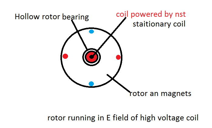
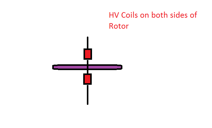
                          This was just to give you guy's some ideas, I wont be building it anytime soon, Im still working on the Don Smith device.
                          Dave

                          The high voltage coil should supercharge the magnets, The main reason Im working on the Don Smith device is because it will give us a basic understanding of whats happening with all coils.
                          Last edited by Dave45; 10-06-2011, 10:33 AM.
                          Half of the Answer is knowing the right Question

                          Comment


                          • "Would you believe each phase winding is only 1.3 ohms but 11.75 mH ! "

                            millihenrys not henrys ? Not surprising unless that's Henrys !

                            What diameter is the wire ?

                            Comment


                            • Chapter 2 page 36 of the PDF in the download qvision linked above (control of Induction Motors) says this.

                              In the braking mode, the rotor is forced to rotate against the stator field,
                              which causes high EMFs and currents induced in the rotor conductors. This
                              mode can easily be imposed on a motor by reversing the field, which is
                              accomplished by interchanging two leads between the power line and
                              stator terminals, that is, by changing the phase sequence. However, the
                              braking torque is low, so that this method of slowing the motor down is
                              not very effective. In addition, both the kinetic energy given up by the
                              load and the electric energy supplied to the motor are dissipated in the
                              rotor winding. Thus, no energy is recovered, and the motor is likely to
                              overheat.
                              Much more efficient braking results from forcing the motor to operate
                              in the generating mode, which requires that the rotor turns faster than the
                              field. This is done by reducing the field speed, n^yn, so that it revolves
                              slower than the rotor. According to Eq. (2.4), it can be done by increasing
                              the number, Pp, of pole pairs of the stator or by decreasing the supply
                              frequency, /. Indeed, certain motors have stator windings so arranged
                              that they can be connected in more than one configuration, yielding, for
                              instance, p^i = 1 and Pp 2 = 2. In the adjustable-speed drive systems,
                              the motor is fed from an inverter, which supplies stator currents of variable
                              frequency. There, the generating mode can easily be enforced by keeping
                              track of the rotor speed and reducing the supply frequency accordingly.
                              Basically it says the best way to slow down the motor is to make it generate
                              by slowing down the rotational speed of the field. Which is funny because
                              Tesla describes the rotating magnetic field generator in this patent below as doing
                              the same thing but in reverse as well and the currents are taken from the
                              armature in this setup. The armature is shown in side view as well below to
                              show the wiring connections.

                              Dynamo Electric Machine Patent.

                              P.S. Where it says "best available copy" on the patent the Y is almost missing
                              so it looks like it says best available COP. But it doesn't.

                              Cheers

                              P.S. in the Tesla setup in the patent above I think he is saying that when the
                              field winding's in the generator are excited, the Armature (rotor) turns with the
                              rotating field. Then to get current from the armature it can be loaded or drive
                              something, which causes the braking effect described in the PDF Quote from
                              qvision but in Tesla's setup this was good because that made output
                              available, same as if the rotor (armature) is driven faster, it generates both
                              ways loaded or driven. Load the rotor it generates, drive the rotor it generates.

                              This is it. I think Telsa's Dynamo Electric Machine is the one for me. I'll try to
                              get a motor working with a normal armature first.

                              ..


                              .
                              Last edited by Farmhand; 10-06-2011, 11:01 AM.

                              Comment


                              • Another way to do this without such a drastic change in system design

                                Changing coil wiring around could produce some interesting effects.
                                By changing the wiring you could have NN or SS or NS, could be fun.
                                I think it would blast any pickup coil around it.
                                Last edited by Dave45; 10-06-2011, 11:17 AM.
                                Half of the Answer is knowing the right Question

                                Comment

                                Working...
                                X