 Tweet
Tweet
Hi blackchisel,
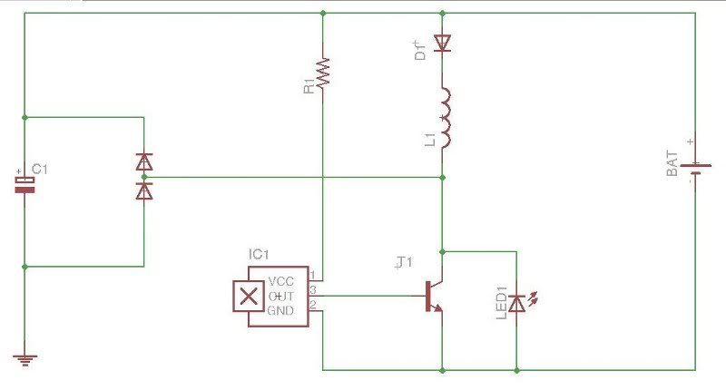
I would give the half bipolar circuit a try. I switched my SSG from the original circuit to the half bipolar circuit and the charging went up. It is very easy to tune if you put a 1K pot in place of the 220 ohm resistor that is used in most of the circuit drawings you see. Also use a hall effect transistor to turn it on and off. Use the hall to adjust the timing and duration of the pulses to the motor coils and use the pot to adjust the current to the motor coils.
Good luck, Carroll
 I'll try to get this done today. I have only MJL21193 which is a bit overkill for this project but together with 21194 they're my favorite tranny's to work with.


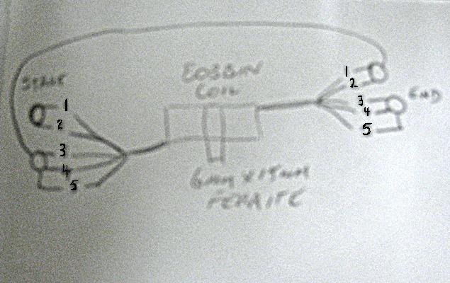
 One question that I think is important and I'm not clear on yet is this: Do you solder the 1,2,3 together to the opposite end where 4,5,6 and 7 are or to the same end where 4,5,6 and 7 are located? I assume the opposite end will be best but please let us know on this. Thanks for this find and your video!
Comment