If this is your first visit, be sure to
check out the FAQ by clicking the
link above. You may have to register
before you can post: click the register link above to proceed. To start viewing messages,
select the forum that you want to visit from the selection below.
Here's something to report, something very positive
Remember the recent diagram posted, where the coil arrangement was shown that Romero used ?
I tried it out tonight.
Out in the backyard, I have several junk monitors, from which any and nearly all recent components have come from. So today I went to the neck of one monitor and removed the Litz type multi-strand wire. I normally have junked that type, because the factory glue used was thought to rip the strand enamel off...but if carefully unwound, it doesn't.
This neck used 7 stranded wire.
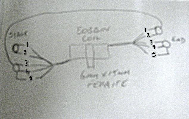
Strands 1, 2 and 3 were soldered to strands 4, 5, 6 and 7. The two ends lots were then used as the power wires for the coil. The coil itself is wound on the actual plastic bobbin that sits on the neck arrangement too, in a little plastic housing. The threaded ferrite core included within the bobbin was kept and remains inserted (you'll see when you take one apart).
Wound with 4 layers of the wire, to the thickness shown in the video below, the coil then had some tape wrapped around to secure.
A small neodymium was placed on the back of the coil, facing North toward the rotor.
It was then fitted to one of my Adams type pulse motors. The rotor is far too small, but what the hey, this was just to see what may or may not happen.
The motor was powered up at 12V and saw the usual speed to be expected from such a size of coil..,fine, normal. Many coils have been tested on this motor, as it's shabby look now testifies to.
Then decided to basically short the coil with a regular CFL house bulb - the rotor sped up to a never before seen speed and kept climbing in RPM !!!
150V AC was measured and then the measurement dropped, presumably from actually measuring the output and killing the dipole ?
The rest of the video shows other 'on the fly' experiments. Some really very bizarre effects were witnessed, including a neon bulb lighting without rotor movement.
Basic Adams type pulse motor:
4x Neodymium magnets, all facing North outward
DN6851 Hall sensor
2SD667 transistor
Small red LED across the Emitter and Base
1N4148 BEMF transistor protection
No caps on the circuit
No shunting doodahs
Hall sensor positioning is critical
Running from a multi-voltage wall adapter, giving approx 3V to 12V range (smoothed by a FWBR and small cap to give more realistic voltage readings at settings and to smooth the supply).
I definitely recommend ripping apart an old monitor and trying this out
Also, apologies for both the mess and hysterical nature within especially the first part of the video
I'll draw one up in a package I use online...never have got used to Eagle, but then again I haven't given it time.
Edited to be correct after looking at the coil -
The start bundle 1, 2, and 3 connect to the finish end 4, 5, 6 and 7.
The start bundle of 4, 5, 6 and 7 form one coil input connection,
The end bundle 1, 2, and 3 form the other coil input connection.
Here's the drawing I based it on:
I will build this new coil design.
I think i understand the wiring see how i go
good work .
if you have a better schematic that will be helpful.
Am transferring the coil to another and probably better unit at the moment. It's a CD based thing and so easier to replicate for similar trials by others.
I'll run that and then wind another coil this evening. If the camera (or webcam) cooperate, i'll show the windings and how they are soldered.
A variable pot is to be used to simulate the CFL. No idea what will do what and i'm intrigued about actual loads too...bulbs, standard DC motors and maybe even the circuit itself. I'd like to see what shortage there is between the AC once rectified and what goes in, then explore shorting ttechniques that use the AC caps a bit more.
A few of these coils around the side of the CD then starts to bear similarities to the Muller design.
But, mainly, as a test unit, the CD one will be better suited than the other.
if you have a better schematic that will be helpful.
I'm fairly sure I understand it now. Easy enough if you have seven strands ohm them out so you know which ones are which on each end. Label them 1 through 7 or some way keep track of them. 1 through 4 on one end get soldered to 5 through 7 on the other end. 5 through 7 on first end go to rest of circuit and 1 through 4 on other end got the circuit. Like this funkadelic drawing by my 4 year old (yeah right )
Notice where he talks about doing this solid state and then saying "short the coil multiple times at every peak of the wave"
As soon as i saw this, i had deja vu! I found part of the source of this info and it was not that long ago that i posted a link to it. I even started a thread on this forum called "Coil shorting techniques" The article below does not mention the multiple shorting but the author does mention it in another article that i cannot find right now. Still, i recommend reading it.
I must be missing something, he's connecting stuff (CFL/neon) across the coil.
JB did this in DVD 2 changing the impedance of the load changes the speed of the rotor.
have you measured the input amps - pretty sure that coil is osculating and using energy to do so. the rotor can not keep up w/ the self osculating part until you change the impedance with a "load", then the juice is allowed to go to the rotor. lots of fun, it will be interesting to see what you are able to do w/ it. the power supply adds another piece to the puzzle as well, the red LED acts as a feedback loop - the transistor could still be switching? or have you scoped it to be sure it is not? interesting vid. sure is making people think :-) thanks...
If you have seven wires in the wire bundle and short 1 and 2 together on both ends as shown, you are shorting wires 1 and 2 internal to the coil.
So the connections indicate a combination shorted and series coil, to me any way.
So there is automatic coil shorting going on along with an output from the coil. A simi shorted out coil.
1 and 2 are shorted out, but back through the coil, not around it, plus the shorted out 1 and 2 wires is still part of the output circuit.
3 4 5 6 7 well may be too
But the internal shorted coils may be, acting as a kind internal boost circuit that when the rotor magnet passes, the current is stored up in the coils magnetic field BTDC and released after TDC causing the rotor to speed up, all automatic.
If it released ATDC, then it looks like the coil core might push against the rotor magnet ATDC, and cancel out any attraction.
The more it speeds up, the more it speeds up, until the boost can't boost any more.
The load on the coil wires was only needed to get it going.
When the load was removed, it just kept on going, as shown in the video.
A CRT defelection coil was never designed to do what it is doing here in this application.
May be this strange internal coil wiring arrangement can get around Lenz.
If so, then the deflection type coil, could act just as a booster coil only for the rotor.
Other "normal" coils could be used as generator coils.
Might work.
One thing to keep in mind is, man wrote the laws regarding the conservation of energy, not nature.
Nature writes it's own laws regardless of what man thinks or does.
If you have seven wires in the wire bundle and short 1 and 2 together on both ends as shown, you are shorting wires 1 and 2 internal to the coil.
So the connections indicate a combination shorted and series coil, to me any way.
So there is automatic coil shorting going on along with an output from the coil. A simi shorted out coil.
1 and 2 are shorted out, but back through the coil, not around it, plus the shorted out 1 and 2 wires is still part of the output circuit.
3 4 5 6 7 well may be too
But the internal shorted coils may be, acting as a kind internal boost circuit that when the rotor magnet passes, the current is stored up in the coils magnetic field BTDC and released after TDC causing the rotor to speed up, all automatic.
If it released ATDC, then it looks like the coil core might push against the rotor magnet ATDC, and cancel out any attraction.
The more it speeds up, the more it speeds up, until the boost can't boost any more.
The load on the coil wires was only needed to get it going.
When the load was removed, it just kept on going, as shown in the video.
A CRT defelection coil was never designed to do what it is doing here in this application.
May be this strange internal coil wiring arrangement can get around Lenz.
If so, then the deflection type coil, could act just as a booster coil only for the rotor.
Other "normal" coils could be used as generator coils.
BTW, R UK said early on, that he used wire out of old computer CRT deflection coils in his coils.
I do think there could be some sort of a connection here.
One thing to keep in mind is, man wrote the laws regarding the conservation of energy, not nature.
Nature writes it's own laws regardless of what man thinks or does.
I've read of the Magnacoaster, but never looked into it...will do though.
Having read every post on the OU thread until yesterday, Romero's use of monitor wire for the posted pic of how he wired his coils was what prompted a replication, as best I could.
Input amps haven't been looked at yet, but i've built up another coil...which also works well. It hasn't been shorted and the rest yet, but I wanted to pass on some findings.
Oh, my scope seems to be shot somehow At switch on, I get a very minor but constant sort of little ripple across the screen and that's all. Knobs and whatnot still work but there's no signal apparently from anything. It could be the leads though. Scope is old - EICO TR-410.
The new coil is slightly bigger, wound on a bobbin also found on the neck of a monitor.
Crappy pics, but here's the build procedure. Left is the bare coil, with the screw in ferrite core seen, then middle is the wire having been wrapped in layers, on the right is the coil with strands soldered and now wrapped in Blenderm type medical tape to protect:
Things noticed immediately on testing. If located very close to the rotor, this thing will rattle and bang on each magnet pass. I noted the sound to be similar to Romero's video...which is all a bit weird in a way. He used sewing bobbins, but, this ferrite inside the monitor bobbin is actually rattling with pure strength within, even though it feels secure. The coil is strong when energized, it pulled 2 magnets off their superglue mounts before a magnet went on the back.
A hum effect can be sensed with the hand if placed on top of the coil. At switch on, with the Hall sensing a magnet and switching on, the coil resonates at a mains type hum. I think that's how the neon lights with no rotor movement, some internal resonance thing.
I like your explanation Steve, must have took more working out than the wires on these coils !
From the size of this coil and looking at Romero's pics, I think the whole 300 turns thing was 50 turns x6 strands.
I'm liking the inbuilt adjustable ferrites on these monitor bobbins...small turns and the effects noted will be, er, noted
OK,
I have officially checked out, this has gone way over my head.
Strands 1 and 2 look to be in parallel not shorted. in fact I don't see any "shorted" strands in this coil schematic, only 2 sets of strands in parallel with themselves, one set with 2 strands the other set w/ 3 strands, then these two sets are in series - and this is being used as the drive coil not a pickup coil?
I'm going to give my old eyes a break - come back to this later and read the posts w/ fresh eyes. thanks...
Indeed dear sir, which is why a CFL was stuck across the back looks like the same logic.
I have no idea how he wound up with such an arrangement or what the prompt was to try it, but it hauls very well and after winding up to a thousand turns of mini gauge wire time after time, these thicker bundles are a delight.
The coil mA draw on my second one is 40mA @12V, so says the Sperry SP-6A.
I haven't seen it perform the shorted speed up phenomena on the other test rotor, so will try it on the original box type one. Looks like the other rotor is more tuned than the supposedly better one i've since been testing with.
Not much is logical with these Romero/Muller methods - and I like it
Wife has decided an order needs to be made with Harbor Freight, she says she often hears shouts at 2am of "so what kind of reading is that supposed to be ?" lol. Would people recommend a couple of the $4.99 red Cen-Tech meters or 1 of the $19.99 clamp types ? I'm worried about busting something with HV, which i'm wondering might have caused the problems with my scope (was it Bolt who has that hilarious video of a meter showing increasing voltage and then he bangs it harshly on the table cos it's actually broken ?).
I ran small test with my setup today and rotor - coil spacing seems critical as far as output wave, additional magnet placing and the drag changes accordingly. I have my coils mounted so start winding is facing stators and end of windings facing rotor. End of top coil is connected to the start of bottom coil. Shorting does very little to the circuit. When I have neon NE2 across the coil and un short manually, depending on the spot (sine wave) I'm getting flash. With proper cap when I hit the peak of sine neon flashes purple. Rotor is going too fast atm, over 3,000 rpm and I think different trigger would be better (lower rpm). My coils are single strand, full sewing bobbin. Both wound cw and starting ends facing stators.
I'll work on harvesting those spikes at the right time and timed dumping, when motor is off. I want to get this done on bipolar transistors if I can.
Edit: I think this may be wrong track. "Normal" coil configuration and serial cap seems better.
V
Last edited by blackchisel97; 06-28-2011, 09:32 PM.
Reason: Edit
'Get it all on record now - get the films - get the witnesses -because somewhere down the road of history some bastard will get up and say that this never happened'
Comment