Announcement

Collapse
No announcement yet.

Muller generator replication by Romerouk

Collapse
X
 
  • Filter
  • Time
  • Show
Clear All
new posts

  • Originally posted by Bruce_TPU View Post
    A nice little write up posted by Nul Points at OU. Like I have said, there are many interesting things to be said about playing with strands...

    http://home.comcast.net/~onichelson/VOLTGN.pdf

    I have completed winding a 4" by 3/4" diameter coil, using Romero's 7 strands and I wound the coil directly onto the ferrite. This increases your wattage gain considerably.

    Over the next several days, I will begin to test it. It is 15.3 ohms, and 116 mH.

    Cheers,

    Bruce
    Here is something for stands.

    looks a bit of a mess. it has given the best figures so far.
    I only need a few more watts to go 1:1 ratio.

    I like litz wire because it is versatile for research

    Comment


    • I agree, if a strand configuration doesn't work, as in your case blackchisel, it may be that you need a different configuration. I'm having much luck with 7 strands, but Romero's drawing was for 5. A 10 wire loony monitor coil has behaved differently than my 2 other 7 strand versions. My rotors are tiny compared to a full Muller build and that has been personally noted.
      If a 'ringing' current lock condition exists, then it's harmonic frequencies would be different for the loads and powerings of each machine. Simple non proven theory but thanks Steve220 for putting me on to that thought. In that light, an oscilloscope would prove out much, before during and after powering a coil.

      Say Penno, i'll draw a circuit up and probably start a new thread if the solid state neon thing works out. The circuit was built, tried out and doesn't work the same as the known way it does on the FanGen. However, i'm using a U18 Hall sensor and, while Bi-polar switching the same as a DN6851, isn't doing it the same...was just the one I have that isn't fitted to a pulse motor already. The point we look for for best switching, where the Hall is to one side of the next magnet and the coil is right behind the face of a magnet is how the setup sits statically. Such that, the switching placement is spot on all the time. The triggering is coming from the AC line ripple of the powering wall adapter. The circuit is merely a transistor switch, Base to Hall sensor, neon across the back of the coil but with a 104 ceramic cap between 1 leg of the neon and one side of the coil. Both neon legs glow well at 6V.
      It should also be noted that a Bedini SSG would likely switch a neon when stationary, but I don't have one. What I mean is, I might just be rediscovering the wheel.
      Just took the case fan out of my PC (eek huh) because it was disconnected and found the Hall to be a 4 legged '277 042F' non SMD...now what in the world is one of those ?
      The 4 leggers are normally SMD and in the smaller Pentium III processor fans.

      By the way N8 - great to hear you got some valuable components from the TV. It's the best feeling when you casually wonder about the prices of parts for an experimental but free to build machine and work out $30 or something

      Comment


      • toranarod: very good experiment!
        I have been following you and "Slider2732" experiment.

        I want to know:
        You do not connect the load speed how much?
        When connecting load speed is much?

        Thank you very much!

        Comment


        • Originally posted by Slider2732 View Post
          I agree, if a strand configuration doesn't work, as in your case blackchisel, it may be that you need a different configuration. I'm having much luck with 7 strands, but Romero's drawing was for 5. A 10 wire loony monitor coil has behaved differently than my 2 other 7 strand versions. My rotors are tiny compared to a full Muller build and that has been personally noted.
          If a 'ringing' current lock condition exists, then it's harmonic frequencies would be different for the loads and powerings of each machine. Simple non proven theory but thanks Steve220 for putting me on to that thought. In that light, an oscilloscope would prove out much, before during and after powering a coil.
          I found two multifilar coils from TV's. One was 7 strands the other 5. 7 strands was only 2m long . I decide to make my own, just enough to test one coil set. Due to the wire avail. I made 6 filar and filled both coils, fitted with ferrite cores and connected strands as described in previous posts. I also hooked up second pair of single strand and doubled FWBR. Now I have both FWBR's in parallel plus 22,000uF across DC. There is more current to the load but slightly less rpm with second bridge connected. I didn't measure anything yet, just visual and scope.
          Also, just for fun, I connected small transformer, 12V output paralleled with stator coil and 110V leads out to the bridge. Connecting transformer had no effect on current draw or rpm and I got 95V DC. This reminds me my earlier replication of Bit's Voltaic Amplifier with center tap transformer pulsed on low side.
          Back to the bench.


          V
          'Get it all on record now - get the films - get the witnesses -because somewhere down the road of history some bastard will get up and say that this never happened'

          General D.Eisenhower


          http://www.nvtronics.org

          Comment


          • Bruce,

            Her's a quote from Blackchisel97 from above.

            "Multistrand in bifilar configuration didn't give better performance, actually, AC was less then single wire".

            THAT'S WHAT HAPPENS WITH MULTISTRAND!

            You are calling the Tesla Hi Voltage single wire series connected bifilar coil a multi strand coil when it's a two SINGLE WIRE coil in the Null Points analysis, to add to your cronic confusion and spreading of disinformation. He's examining a standard "Joule Thief" type wrap where the current is running backwards against itself in a SINGLE WIRE. Try to understand that Bruce! Multi strand bifilars destroy that effect.

            These results were hard won by me after long experimental trials with my Quadfilar Spiral coil, built by me based on your false assumtions, only to get the same negative results as Blackchisel97. Don't further accuse me of not having any builds, or experimental data. Find out why it dosen't work with multistrand instead of trying to pretend it does!
            Last edited by synchro; 07-04-2011, 05:01 AM.

            Comment


            • Originally posted by toranarod View Post
              Here is something for stands.

              looks a bit of a mess. it has given the best figures so far.
              I only need a few more watts to go 1:1 ratio.

              I like litz wire because it is versatile for research

              Hi toranarod,

              Have you attempted to make your drive coils bifilar also, and seeing if you can reduce the voltage, as Slider was able to and still maintain the same RPM's?

              Another interesting experiment for you would be from going bifilar to trifilar. Right now, you have 123 going to 4567. Try the following with 1 set of coils and see if there is an increase in wattage... 12 going to 34, 34 to 567. The magnetic field will expand three times within itself, in to out, in to out, in to out.

              You are very close and one or both of these items may bring you closer to your goal.

              Cheers,

              Bruce

              Comment


              • Synchro, I just stated what happened in my setup. I'm not trying to prove or disprove anything as I try to understand this device. All I want is to replicate what Romero did and have small, self running generator on my table.
                I did some tests with shorting coil. Interesting, when I connected neon across and moved sensor I saw neon either glowing in the center or on side. Center glow was at approx. right spot - peak of sine wave (I had scope connected as well). With those spikes plus coils output plus BEMF recovery it seems to be enough. Still, what bothers me is Romero's original design which he wanted everyone to replicate. No caps, no coil shorting, he didn't even mention bifilar.
                One more thing; he said that there are two halls, one triggers from small rotor magnets and second from rotor magnets, approx 1mm after magnet passes coil. Is it possible that this hall was used for shorting coils, not for other trigger? Position would be correct. Just thinking loud. There was no other circuit visible beside two driver boards so I'm probably wrong.


                V
                'Get it all on record now - get the films - get the witnesses -because somewhere down the road of history some bastard will get up and say that this never happened'

                General D.Eisenhower


                http://www.nvtronics.org

                Comment


                • 2nd Hall.

                  Blackchisel97,

                  I believe the 2nd Hall definitly shorted the coil, and it's positioning for timing is critical. The discharge has to remain at 180 degrees from the pulse to the power coils.

                  Comment


                  • Originally posted by synchro View Post
                    Blackchisel97,

                    I believe the 2nd Hall definitly shorted the coil, and it's positioning for timing is critical. The discharge has to remain at 180 degrees from the pulse to the power coils.
                    Thanks synchro, it makes sense. I couldn't figure out how such position could warrant triggering of second driver circuit which has to be "on" when the first one is "off". Unless I'm wrong, of course. I never worked with mosfets and it is my understanding that they have to be handled carefully since the static may damage them, as well as transformer type soldering gun should be avoided. Am I correct? Maybe silly question but I started learning on vacuum tubes (my first ham amp. was built on them) and I didn't work with electronics for 20 years, until meeting J.B, couple years ago. I can visualize getting switching part done with bipolar transistors instead but perhaps mosfets are better? Dunno


                    V
                    'Get it all on record now - get the films - get the witnesses -because somewhere down the road of history some bastard will get up and say that this never happened'

                    General D.Eisenhower


                    http://www.nvtronics.org

                    Comment


                    • Hi Blackchisel, I don't seem to have problems with my soldering iron and mosfets, I don't solder with it while the circuit is grounded though, only isolated. If I could offer that I think a MJL21194 is a very good switch and probably as good or better in some ways than a mosfet. I do occasionally have Fets that seem to end up ruined and always conducting but it is usually from overvolting them with spikes or something that would also ruin a Bipolar.

                      I would stick with what you're comfortable with. I'll be using a bipolar I think to try for a similar motor energiser inspired by this thread. It should be a lot easier to drive from a higher voltage for me.

                      Cheers

                      Comment


                      • Originally posted by Farmhand View Post
                        Hi Blackchisel, I don't seem to have problems with my soldering iron and mosfets, I don't solder with it while the circuit is grounded though, only isolated. If I could offer that I think a MJL21194 is a very good switch and probably as good or better in some ways than a mosfet. I do occasionally have Fets that seem to end up ruined and always conducting but it is usually from overvolting them with spikes or something that would also ruin a Bipolar.

                        I would stick with what you're comfortable with. I'll be using a bipolar I think to try for a similar motor energiser inspired by this thread. It should be a lot easier to drive from a higher voltage for me.

                        Cheers
                        Thanks, I appreciate. I'm comfortable with bipolar while mosfets are totally new territory I only burnt one MJL so far and that was my mistake. I used shicklay and totem poles for switching before and they worked well also, in solid state running much faster than this device. I'll give a try. I need to read back all Slider's post. This is interesting.

                        V
                        'Get it all on record now - get the films - get the witnesses -because somewhere down the road of history some bastard will get up and say that this never happened'

                        General D.Eisenhower


                        http://www.nvtronics.org

                        Comment


                        • Originally posted by yx630514 View Post
                          toranarod: very good experiment!
                          I have been following you and "Slider2732" experiment.

                          I want to know:
                          You do not connect the load speed how much?
                          When connecting load speed is much?

                          Thank you very much!

                          My test motor is large and heavy unit that i designed to support lots of experiments. I use
                          8 Rod Magnets 30 x 25.4mm N45 Rare Earth 6000 gauss on the rotor supported by 9 coils.
                          At the moment there is only two coils set for drive and generation. She a brute not built for speed. When this thing is doing 1500 RPM the ground shakes.

                          I want to know:
                          You do not connect the load speed how much? 850 RPM
                          When connecting load speed is much? 1125 RPM

                          If there was a reduction in speed this would not be worth a mention on the forum.

                          I am going to try a few more configurations like the one in my drawing.

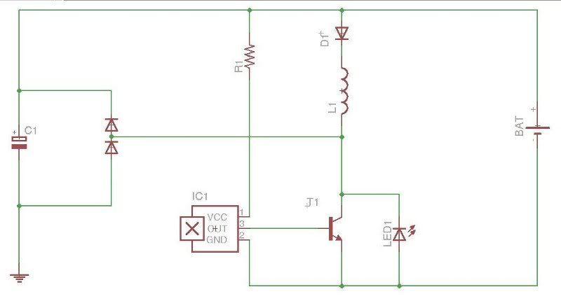
                          The wave for below is from TP1 on the schematic.


                          Comment


                          • Originally posted by Slider2732 View Post
                            Here we are with the circuit.
                            I use the same one for any pulse motor and it's just an own design when I couldn't get a Bedini SSG circuit to run (all components are salvaged and that's probably why).
                            It's the one that 'downunder' kindly redrew for me some while back, when the first pulse motor did the supercap and 6V battery thing. The Ground from the cap is actually a return to the negative of the battery btw.

                            Hi Slider,

                            Just to be sure I'm going about this the right way, can you confirm
                            that you simply placed the neon directly in parallel with the coil ?

                            Penno

                            Comment


                            • Originally posted by synchro View Post
                              Blackchisel97,

                              I believe the 2nd Hall definitly shorted the coil, and it's positioning for timing is critical. The discharge has to remain at 180 degrees from the pulse to the power coils.
                              You are definetly wrong here, when you would had followed the Schematics from the Muller Thread over at OU.com

                              Synchro,
                              Can you please stop now your offending Postings, or go back to OU.com?
                              There you can open a new Thread where you can discuss about Bruce's Opinion,
                              and he can join you, when he is interested. But this Thread is not the right Place for, to start fighting about Opinions.


                              Else i only can suggest, that anyone reports you with the red Button right Top, who dont agree with your Postings here.
                              Last edited by Joit; 07-04-2011, 02:28 PM.
                              Theorizer are like High Voltage. A lot hot Air with no Power behind but they are the dead of applied Work and Ideas.

                              Comment


                              • Bipolar verses MOSFETS

                                Originally posted by blackchisel97 View Post
                                Thanks, I appreciate. I'm comfortable with bipolar while mosfets are totally new territory I only burnt one MJL so far and that was my mistake. I used shicklay and totem poles for switching before and they worked well also, in solid state running much faster than this device. I'll give a try. I need to read back all Slider's post. This is interesting.


                                V
                                Bipolar verses MOSFETS

                                As a rule in electronics for high voltage coil switching you would never use MOSFETS
                                All automotive ignition coil and TV EHT transformers use bipolar transistors for switching. Bipolar transistors are not prone to damage by high voltage spikes.
                                The funny thing is we need High voltage spikes for our BEMF to work properly and this will kill a MOSFET ASAP.
                                SO why do I use MOSFETS for all my switching circuits when they are the worst possible choice?

                                Because the ultimate goal of all this work is OU .

                                To achieve OU you need two things very efficient drive circuits and very fast drive circuits. To make a bipolar transistor switch fast it takes large amounts of current and more drive stages. This is ok in a TV or a Car where current consumption is not important. But for your research this is a big problem.
                                In electronics we say Bipolar are current switching devices and MOSFETS are voltage switching devices.
                                During a day on the bench testing new ideas and theory I usually destroy many FETS.
                                When I buy them I do so in lots of 50 to 100 because they are disposable in this field of work. It’s taken a long time to develop switching circuits that can shield the MOSFET while allowing it to do it job. You can see some of this if you look at the top end of my last post schematic.
                                But the end justifies the means.

                                cheers

                                Comment

                                Working...
                                X