Announcement

Collapse
No announcement yet.

Lighting Fluorescent Tubes with Voltage

Collapse
X
 
  • Filter
  • Time
  • Show
Clear All
new posts

  • #16
    Hi Geotron, I'm distracted again now. I was completely engrossed in my experimenting. Umm actually I'm finding that i can only get 4.6 Khz or so with the newer circuit. When I originally tried the CFL directly from the ignition coil I used a circuit the same but it was a temporary one and I can't remember the timing cap value, anyway this circuit is different but only in the frequency/PW. I am trying so much stuff I am getting confused, this is so much fun.

    The way I have the TC secondary connected to the primary and ground and the ignition coil negative is also grounded, which is a must if driving the HV open ended. Anyway I think it makes it so that the CFL's are forced to light, i'm not sure how it does not force the voltage to go directly from the TC primary then up the tower wire just like a wire connection. Not sure it is such a good idea. It works though.

    The volcano setup is a capcitive spark gap, I can use it in parallel with the HV or in series and if I adjust the gap it give's a voltage limit.

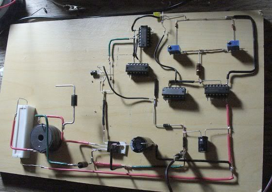
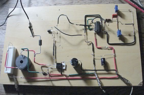
    I'm running the Ignition HV through the thick TC primary then the primary wraped on the stick in the photo below, I can get thousands of volts into a microwave cap from the small center tapped coil on the tube, but the microwave cap has a resister in it too, so it bleeds away fast. Damn resistors To make the gap spark I just disconnect the Tower secondary negative from the primary and ground the tower negative then the primary grounds through the spark gap. I need a 1 uf or so HV cap for the spark gap to work well I think.

    There is a lot of unecessary stuff in the picture, for experimenting, I have gone to a spiral primary now for the TC and I'm playing with a spark gap now.
    http://wv0v9q.bay.livefilestore.com/...001.JPG?psid=1

    My bench is an incredible mess but everytime I try to clean it up I end up experimenting some more because I get more idea's.

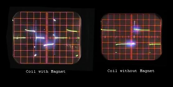
    I didn't remove the resistor just wired the setup different. It's handy to know about the 2500 volts I think I am getting about the same voltage I thought it would be more but I guess the peaks are high and the average is less.

    The plate behind the tower coil is just a radiant energy collector plate "P", it is connected to a cap to collect radiations or emanations. The bowl is just a virtual ground/ connector bus, whichever experiment I'm doing.

    I cant seem to get the CFL's to light when I use the spark gap, but neons light wirelessly a lot better. Now I want to try wireless an one wire transmission, I need to wind another tower coil, and also a pair of spiral coils that fill the plastic plates they will be transmission experiment coils.
    NIKOLA TESLA - Google Patents

    I have an idea for an arrangement to pulse the 2 turn primary (around the pancake coils) kind of directly from my circuit with no spark gap so it is like an exciter for transmission experiment's. But I will have to make my own flyback with a fair bit less peak voltage than the Ignition coil. The problem is a thick primary has little self inductance so I will need to introduce more self inductance to the circuit, Tesla used large self induction coils which charged on the closing of the circuit and discharged into a cap or caps which disharged through the thick 1 or 2 turn primary suddenly. If I reduce my voltage I can find caps easier.

    I think the voltage is too high to recover any usefull amount without a lot of HV caps.

    Anyway now I had a sleep I can get back to it. For another 48 hours.

    Cheers
    Last edited by Farmhand; 06-06-2011, 08:07 AM.

    Comment


    • #17
      Here again is the desulfator circuit in another form... its got me curious
      as to whether the output may be hooked onto the source battery without voltage
      regulation to the signal generator.

      Couldn't the output from each side of the inductor also be gathered into a
      fullwave bridge and then used to charge a capacitor - Zener diode combination
      so that when the cap is charged up to 50V or so it would automatically short
      onto the battery?

      Added to the diagram is a diode from the source to the drain of the transistor
      and a 10k resistor + 100nF cap for snubbing spikes... leading me to question
      whether these additional protective elements would serve to impede the function
      of the circuit... ?

      Comment


      • #18
        Originally posted by geotron View Post
        Here again is the desulfator circuit in another form... its got me curious
        as to whether the output may be hooked onto the source battery without voltage
        regulation to the signal generator.

        Couldn't the output from each side of the inductor also be gathered into a
        fullwave bridge and then used to charge a capacitor - Zener diode combination
        so that when the cap is charged up to 50V or so it would automatically short
        onto the battery?

        Added to the diagram is a diode from the source to the drain of the transistor
        and a 10k resistor + 100nF cap for snubbing spikes... leading me to question
        whether these additional protective elements would serve to impede the function
        of the circuit... ?

        Hi Geotron, so that is where that diode go's, from source to drain, I see the mosfet already has one doesn't it ? Does that one releive the burdon on the mosfet ? So a lower forward voltage one than the fet ?

        I don't understand the diode 11 and the resistor there.

        Not sure about the snubber around the coil if you want the spike's I would leave it out, but that would work to supress them I guess.

        Is the coil the primary of a transformer ?

        If you use a FWBR on the single coil recovery it might work or a bifilar with a FWBR on the second winding might work too to loop it. My way of thinking is that the recovery and the positive rail on the AC of the bridge will still give the DC negative out of the Bridge a 12 volt reference or ground point. And so may not like trying to charge across the battery, I might be wrong.

        But with a second winding it is isolated from the supply and so make's it's own 0 volt negative reference point or ground. And wont mind being placed across the source. I'm not certain a single winding won't work.

        The diode from drain to source looks like a very good idea, though.

        I almost have another different circuit based on the desulfator finalised and will post a drawing of it soon.

        Cheers.

        Comment


        • #19
          flux-field effect

          The way Desulfator is shown in the Rev 1.0 diagram, I'm seeing the target
          battery connected in series with the source in such a way as to allow D2 to capture
          out the voltage spikes generated by pulsing the coil and direct them onto the (+)
          pole when the transistor closes ... Providing this is true, the waveform may
          acquire a more useful characteristic by causing its operation within close range
          of a magnet.

          Thanks to you nilrehob for allowing me to previously share screen captures of your
          demonstration of this natural phenomenon in discussion on the Tesla Switch.

          Comment


          • #20
            Plasma Lighting

            is the future of outdoor lighting - YouTube - ‪Flashlight Experiment LEP vs LED‬‏

            Comment


            • #21
              desulfator build

              Well I've now put together a model of the Desulfator that seems to not want
              to produce a signal. The transistor is a php18nq10t 18A mosfet, while the
              chips are cd4001ube. Both of the electrolytic capacitors are rated at 50V.

              While no signal is being detected, there is a voltage on the signal output of
              approximately 200mV. This has me quite confused. The only changes I've implemented
              to the circuit are a hefty 1KV diode from the source to drain and a 1n4007 from
              the (-) return of the timer portion to possibly block a dangerous spike from
              reaching through onto the chips...

              Otherwise I have disconnected the transistor just to see if doing so would allow
              a signal to be picked up; no success yet.

              [ Video - Desulfator Malfunction ]

              Comment


              • #22
                Originally posted by geotron View Post
                Well I've now put together a model of the Desulfator that seems to not want
                to produce a signal. The transistor is a php18nq10t 18A mosfet, while the
                chips are cd4001ube. Both of the electrolytic capacitors are rated at 50V.

                While no signal is being detected, there is a voltage on the signal output of
                approximately 200mV. This has me quite confused. The only changes I've implemented
                to the circuit are a hefty 1KV diode from the source to drain and a 1n4007 from
                the (-) return of the timer portion to possibly block a dangerous spike from
                reaching through onto the chips...

                Otherwise I have disconnected the transistor just to see if doing so would allow
                a signal to be picked up; no success yet.

                [ Video - Desulfator Malfunction ]

                Hi Geotron, Nice setup, how come you used 4 chips ? Each chip has 4 gate's, so only one chip is needed. But 4 should work too, I think you will need to supply power and ground to each chip, one chip would be better because of less signal trace length, but as I said it should still work if all the chips have power and ground.

                Don't connect a coil until you have a reliable pulse out..

                I'll have a good close look at you're wiring and see what I can see.

                Please be patient. I need to rotate you're pic it's upside down for me.

                I'll be back.

                Oh yeah try adjusting the frequency pot to about 80 or 90 Kohms and the Width pot to about 3.5k to 4k or so. What value timing cap are you using ?
                If it's 0.001uf then that should give you about 12 Khz and a 1.5 us PW.
                Last edited by Farmhand; 06-30-2011, 03:49 AM.

                Comment


                • #23
                  Ok yes I see, you seem to have made all the correct connections but used 4 chips.

                  With four separate chips they will all need power and ground connections to pin 14 and 7 respectively, and you will need to use only one gate from each chip, each gate has three terminal two inputs and an output.

                  EG, Gate 1 on each chip is pin 1,2,and 3, pin 1 and 2 - inputs, pin 3 output.

                  Each of the gate's represented in the drawing are all part of one chip but can be used separately.

                  Anyway it should work ok if all chips have power and ground because they are just sending a signal around and back and forth then out.

                  If you are still unsure I will expain it better and make a sketch to help.

                  Cheers

                  Comment


                  • #24
                    Umm I think you might also have you're chips around the wrong way, double check where pin one is on the chip with the data sheet because I think pin 1 and 14 are at the end with the half circle notch.

                    I think it is quite difficult to damage these chips, so they should be good to go. It is all very confusing for sure. And it still is for me too it just gets less confusing over time.

                    Hopefully minor problems and easily fixed.

                    Cheers

                    Comment


                    • #25
                      Excellent clues! I've been over to the datasheet and it
                      looks like the cutout is indeed on the side of question...

                      That's interesting they would all communicate properly if each is supplied with
                      voltage, I see what you mean.

                      Using the fullwave bridge across a single coil, couldn't the AC inputs (recieving DC)
                      have their connections at the cathode of the diode on the source and also that of
                      the one leading to the (+) desulfating battery? Could the output go into charging a
                      recovery capacitor connected in series with the source battery?

                      Might the diode on the source also lead into the drain as well as the bridge?

                      Comment


                      • #26
                        Originally posted by geotron View Post
                        Excellent clues! I've been over to the datasheet and it
                        looks like the cutout is indeed on the side of question...

                        That's interesting they would all communicate properly if each is supplied with
                        voltage, I see what you mean.

                        Using the fullwave bridge across a single coil, couldn't the AC inputs (recieving DC)
                        have their connections at the cathode of the diode on the source and also that of
                        the one leading to the (+) desulfating battery? Could the output go into charging a
                        recovery capacitor connected in series with the source battery?

                        Might the diode on the source also lead into the drain as well as the bridge?

                        Interesting drawing again and interesting questions, good one's.

                        The answer to the first question is , I'm not sure but it is an interesting idea and i think I would like to try it and see what happens, it seems it could work. I usually place the bridge between the drain diode cathode and the pos + of the battery or positive rail.

                        Definately the best way to charge caps is with it in series with the battery pos + or pos + rail because the cap zero voltage is referenced to the circuit pos + so the BEMF in the coil is 12 volts at the lowest, if a cap with it's negative referenced to the circuit ground is charged there is an initial excessive input current because all the BEMF from the coil is removed down to the cap voltage until the cap voltage exceeds the source then things get normal. When all the BEMF is removed to a lower voltage it allows a lot more current to flow from the source. This can be seen if you charge a 6 volt battery from the recovery diode of a 12 volt powered circuit, like a Bedini machine or the desulfator, if a 24 volt battery is charged the input current is much less at the same tuning because the BEMF below 24 volts is not removed and still opposes the flow of current.

                        As long as you don't try to loop it back to the source it's fine. It kinda depends what you want to acheive as to how to go about it.

                        Yes the diode could go from source to drain aswell because there is already on there in the Mosfet so another one can't hurt.

                        I like you're drawing can you keep us posted if you try that ?

                        Oh here is a drawing for another way to drive Ignition coils, they are basically in parallel but the polarities are opposing so their outputs are opposite polarity but in phase with each other. HV between the Coil high tension leads. Caution !! depending on input it could be very dangerous, I only use 12 volts on ignition coils.

                        The person who showed me this said to not use more than Iuf cap across the coils.
                        https://skydrive.live.com/?cid=32a91...1255&sc=photos

                        Cheers

                        Comment


                        • #27
                          I think the FWBR should be rectifying the voltage between coil end, not between MOSFET end. Connected like that usual circuit may draw more than a double of current.

                          Comment


                          • #28
                            Then the 12v from the source battery entering the coil sets a voltage
                            potential reference for the output from the other side going through the schottky,
                            the level where its positive voltage output into the (+) pole begins to register?

                            [ battery desulfation charge effect ]

                            Ultilizing a dual set of batteries, it seems uncertain as to whether they would both
                            recieve the desulfating energy... how's this look?


                            Comment


                            • #29
                              Hi Geotron, I'm a bit confused by you're drawing but that's nothing new for me, I'll have to look at it for a bit. The battery polarity looks wrong. Can you put some symbols on there or a brief explanation of the idea ?

                              More importantly did you get a pulse out from the logic chip ?

                              You will most likely experiment with the circuit recovery part and discover things that others haven't, everyone's way of looking at circuits is different and I must miss a lot for a lack of understanding what I'm looking at. I just try to remember what works for me and what doesn't from what I've tried.

                              I can't wrap my head around that circuit but like i said that is likely my fault.

                              Comment


                              • #30
                                Originally posted by sucahyo View Post
                                I think the FWBR should be rectifying the voltage between coil end, not between MOSFET end. Connected like that usual circuit may draw more than a double of current.
                                Hi Sucahyo, I think you might be right. I think I see why too but it is confusing to me. Thanks for the input.

                                Comment

                                Working...
                                X