Announcement

Collapse
No announcement yet.

The Lockridge triflar coil

Collapse
X
 
  • Filter
  • Time
  • Show
Clear All
new posts

  • #31
    I have now added the regenerative circuit to the rotor coils, this should in effect almost double the power of the motor as the magnetism of the recovery from the coils is now being used. I have also arranged the coils in the rotor in a more realistic fashion and added the brushes (relay) on the other side of the rotor.

    This is 80% of the circuit and should run in overunity. Even allowing for a mechanical efficiency of the motor being 35% and the overall efficiency of the generator being 70% we should still have a COP of 2.5. Because the output of the generator is running the motor the COP is actually infinity but I don't think people could handle that.

    Edit

    An error in my calculations, COP still less than 2
    Attached Files
    Last edited by mbrownn; 09-09-2011, 10:36 AM.

    Comment


    • #32
      Originally posted by Shadesz View Post
      I am following as best I can. I have lots to learn. Can you please post the import text for that circuit?
      Text as promised.

      $ 3 5.0E-7 11.558428452718767 59 5.0 50
      l 520 288 520 416 0 1.0E-4 0.0
      l 472 304 568 400 0 1.0E-4 -3.264509196299059E-8
      v 912 504 912 360 0 0 40.0 120.0 0.0 0.0 0.5
      c 752 360 752 504 0 3.2999999999999996E-5 212.50964014051416
      w 752 352 752 360 0
      w 704 184 704 192 0
      l 592 352 456 352 0 1.0E-4 -3.27582014847394E-8
      l 568 304 472 400 0 1.0E-4 0.0
      d 752 504 800 504 1 0.805904783
      l 536 224 504 224 0 1.0E-4 -4.722883240814143
      l 544 488 504 488 0 1.0E-4 -4.722883240814145
      178 408 352 424 352 0 2 2.0000000000000002E-7 -0.5 0.05 1.0E11 0.02 20.0
      v 408 384 408 400 0 2 500.0 5.0 5.0 0.0 0.5
      w 504 224 504 240 0
      T 672 192 704 200 0 0.0050 1.0 -4.722883240814152 -4.722883240814151 0.999
      w 672 192 704 224 0
      w 704 504 600 504 0
      w 456 352 424 336 0
      d 672 392 704 360 1 0.805904783
      d 704 424 672 392 1 0.805904783
      d 736 392 704 360 1 0.805904783
      d 704 424 736 392 1 0.805904783
      w 752 352 632 352 0
      w 408 184 704 184 0
      w 408 304 408 184 0
      w 600 504 600 432 0
      w 704 360 752 360 0
      w 736 184 704 184 0
      w 672 392 672 496 0
      w 408 352 368 352 0
      w 504 240 656 240 0
      w 368 488 504 488 0
      w 656 488 656 240 0
      r 752 360 800 360 0 0.02
      s 568 400 600 432 0 0 false
      s 592 352 632 352 0 0 false
      w 472 304 424 288 0
      w 704 424 704 504 0
      w 504 488 504 496 0
      w 704 504 752 504 0
      w 736 392 736 184 0
      w 504 496 672 496 0
      w 656 488 544 488 0
      c 800 360 800 504 0 0.09999999999999999 117.74766222791469
      w 800 360 912 360 0
      r 800 504 912 504 0 5.0
      r 536 224 616 224 0 0.046
      r 616 224 672 224 0 0.5
      v 368 488 368 352 0 0 40.0 11.0 0.0 0.0 0.5
      o 3 64 1 291 2624.5978164852495 0.0 0 -1
      o 2 64 1 291 149.65776766268445 9.765625E-55 1 -1
      o 3 64 0 290 244.94416553286712 9.797766621314686 2 -1
      o 32 64 0 290 279.96809277222553 5.599361855444511 3 -1
      o 32 64 0 33 149.65776766268445 11.972621413014757 4 -1

      Comment


      • #33
        Motor inductance

        The effect of motor inductance on the Lockridge device is many fold

        Low inductance means low BEMF which is good

        Low inductance means high current draw which is good and bad depending upon the voltage.

        Low inductance means high frequency, Very bad on a mechanical device and power limiting on electronic switching too.

        Low inductance means low efficiency, Bad

        Overall higher inductance is better.

        Resistance is a loss and is always bad so the armature resistance should always be low

        To keep the frequency down to a reasonable level a higher inductance on the trifler coil can work to some extent but this also reduces the voltage on the motor and reduces the motor power. The resistance of this coil should also be as low as possible to reduce losses. This coil had the purpose of compensating for the lack of inductance in the motor and providing impedance without undue resistance, effectively providing inductance without BEMF. Overall it has many benefits on top of the recovery.

        Every aspect of the lockridge device is a compromise.

        Comment


        • #34
          An interesting point relevant to the trifler coil http://www.energeticforum.com/renewa...tml#post160251

          Comment


          • #35
            I have seen this video on the internet, TransVerter / Part 3 - YouTube So there is no point holding back anymore. He is using the Lockridge circuit

            Here is some if the things I have been doing Circuit Simulator Applet

            The left circuit is the one used by Lockridge and the right circuit is the simplified circuit. The problem Lockridge had was he could not switch fast enough so needed more inductance but the trifilar coil also had the benefit of being able to collect radiant. My circuit only shows a bifilar as the simulator cannot represent a trifilar coil. Note the difference in input and output power. The higher the frequency and voltage the higher the COP

            Here is the same thing using MOSFETS Circuit Simulator Applet Notice the COP

            We really need to get these things built. Please contact me to find out more. I believe it is the real thing and thank Peter Lindemann for his video's helping me to work this out. I also thank John Bedini for his great work and for releasing so much to us.

            Comment


            • #36
              To make a self running motor generator we have to improve efficiencies and recycle.

              Most electricity is NOT consumed in a DC motor, it just passes through it. Never saturate the coil in the way it is done with DC motors as this is a waste of energy, charge up its coils and then discharge it to a capacitor, that way you save the energy so that you can reuse it. We can collect this and use it to power the next pulse with a little top up from the source. The current continues to flow in the coils giving us the magnetic field during discharge, effectively doubling the energy with each pulse, because we collect that energy we do not need as much for the next pulse. We can run a motor with 100w but only consuming a tiny fraction of that from the source. The source can be a generator mounted on the motor. To make this work we have to mitigate the losses caused by BEMF. This is done by using high voltage but current limited by pulsing, exactly what we need to recover energy from the coils. The motor is run at its normal speed and power, but with high voltage. The frequency of the pulse needs to be fast enough so that the charge and discharge times are similar. The duration of the pulse is 50%. This will work with standard DC motors and universal motors; It will also work with some pulse motors and is compatible with parallel path motors of the right design. Tesla is right, high voltage pulsed DC is the future

              I have blurted it out now go out and build it and report back here.

              If you make a fortune out of this please remember who gave you it.

              Comment


              • #37
                Nice work mbrown All this work and I am surprised there is not more interest. I'm saving the pages to study later but it sounds like you are onto some very good things here.
                There is no important work, there are only a series of moments to demonstrate your mastery and impeccability. Quote from Almine

                Comment


                • #38
                  Guided Build

                  Mbrown

                  Many thanks for all your work on explaining the Lockridge device.
                  I know there are quite a few on the forum who have been attempting a replication of the Lockridge device using VW generators etc without success.

                  How would you feel about directing the building to test out your circuit and get some hard data to prove / disprove the circuit? Say using the VW generator as a base (that’s if it’s suitable or your recommendation). Anyone joining in the build, understands that this may or may not work, but will give more info into the public domain.

                  As you may know I built what I interpreted as the trifilar coil but I haven’t really moved on since making that, and would defiantly appreciate some guidance.

                  Any help in directing the way forward I know will be much appreciated by many here. I hope you can help!

                  Regards

                  John

                  Comment


                  • #39
                    That is what I am asking people to do.

                    The first thing is to get a motor or DC generator that will run as a motor. It needs to be low friction, low resistance and relatively high inductance. to keep the BEMF as low as possible a low voltage motor would be better but it does seem as if to get the inductance we need we may have to go for a slightly higher voltage motor. Then we need a PWM that runs at 110 to 220v, modify the output so that it switches both on and off at the same time so that we con collect the inductive kickback. We will need to be able to adjust both frequency and pulse width. I don't think we can get a high enough frequency with a commutator for modern motors. Then with a big electrolytic capacitor connect it up as I have shown on my circuit. If you have a variac it may help and prevent burning things out. Once we are at that stage we can start to proceed.

                    As far as the trifilar coil is concerned we may not need it if we use enough voltage and high enough frequency.

                    I am more than happy to help

                    Comment


                    • #40
                      I have been working on a problem with the DC motor efficiency for my Lockridge device. Using a motor that has 70% efficiency with DC I ran a test on pulsed DC, The efficiency had dropped to below 30% making it very difficult to to recover enough energy make the system run in overunity. I believe this is because of the iron losses. I also believe this is why a universal motor is quoted as being 35% efficient when running on AC. While this is bad news in one way it is good in another, it means that on DC a universal motor is more efficient than quoted.

                      Now we have a problem, how do we run a universal motor on pulsed DC and get the efficiency of DC. The answer is already being used today on pulse width modulation, we use a diode across the motor allowing the inductive kickback to return to the input line but this prevents us recovering the inductive spike and feeding it to the capacitor in the source line.

                      I believe I might have the solution and it IS the trifler coil, more on this later after I have made the tests. The solution has another side effect, HUGE kv spikes and this is why we have a trifler coil and not just a bucking coil so that we can collect those spikes. Having said that these spikes are not required to make the system work and are just another benefit. If we don't collect these spikes we will have huge arcs on the commutator and this may be the reason why the electronics on John Bedini's unit could not cope.
                      The Lockridge device is possible

                      This is to let you know I am still working on it and making progress.

                      Comment


                      • #41
                        Hi mbrownn, here is the info I think is useful. The document linked below is
                        large 29 mB. I seriously need to buy a hard copy. I'm going to try after I make
                        this post it's a fine book..

                        Anyway about halfway down page 41 starts the section it finishes at page 44.

                        http://ia600302.us.archive.org/16/it...00martiala.pdf

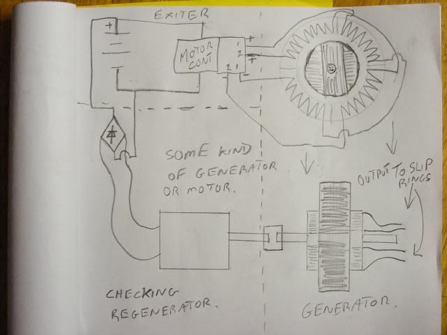
                        In my opinion it basically says, if you drive the field coils with the exciter, the
                        armature will turn with the rotating magnetic poles in the field ring, then if the
                        armature rotation is loaded or spun faster currents will be generated or
                        induced whichever is the correct word, in the armature coils. The interesting
                        thing is if the armature/rotor is loaded (checked) by another generator the
                        effect would be to cause the rotating poles to induce currents in the armature coils
                        while that second generator could supply the input for the exciter at least in
                        part. The generated currents in the loading generator should be proportional
                        to the increased current drawn by the exciter. I think.

                        Any other recoveries from the motor or transformer driven from the
                        armature currents could also be utilized. As we usually do.

                        I'll draw a sketch to show what I mean.

                        The document is written in a rolling style hard to follow.

                        Considering the operative conditions
                        of a system thus established, it will be found that when
                        the exciter is driven so as to energize the field of the generator,
                        the armature of the latter, if left free to turn, would rotate at a
                        speed practically the same as that of the exciter. If under such
                        conditions the coils F F' of the generator armature be closed
                        upon themselves or short-circuited, no currents, at least theoretically,
                        will be generated in these armature coils. In practice
                        the presence of slight currents is observed, the existence of which
                        is attributable to more or less pronounced fluctuations in the intensity
                        of the magnetic poles of the generator ring. So, if the
                        armature-coils F F' be closed through the motor, the latter will
                        not be turned as long as the movement of the generator armature
                        is synchronous with that of the exciter or of the magnetic poles
                        of its lield. If, on the contrary, the speed of the generator armature
                        be in any way checked, so that the shifting or rotation of
                        the poles of the field becomes relatively more rapid, currents will
                        be induced in the armature coils. This obviously follows from
                        the passing of the lines of force across the armature conductors.
                        The greater the speed of rotation of the magnetic poles relatively
                        to that of the armature the more rapidly the currents developed
                        in the coils of the latter will follow one another, and the more
                        rapidly the motor will revolve in response thereto, and this continues
                        until the armature generator is stopped entirely, as by a
                        brake, when the motor, if properly constructed, runs at the speed
                        with which the magnetic poles of the generator rotate.
                        The effective strength of the currents developed in the armature
                        coils of the generator is dependent upon the strength of the
                        currents energizing the generator and upon the number of rotations
                        per unit of time of the magnetic poles of the generator;
                        hence the speed of the motor armature will depend in all cases
                        44 INVENTIONS OF NIKOLA TESLA.
                        upon the relative speeds of the armature of the generator and of
                        its magnetic poles.
                        It will be observed in connection with this system that on
                        diminishing the resistance of the external circuit of the generator
                        armature by checking the speed of the motor or by adding
                        translating devices in multiple arc in the secondary circuit or circuits
                        of the transformer the strength of the current in the armature
                        circuit is greatly increased. This is due to two causes : first,
                        to the great differences in the speeds of the motor and generator,
                        and, secondly, to the fact that the apparatus follows the analogy
                        of a transformer, for, in proportion as the resistance of the armature
                        or secondary circuits is reduced, the strength of the currents
                        in the field or primary circuits of the generator is increased and
                        the currents in the armature are augmented correspondingly.
                        For similar reasons the currents in the armature-coils of the
                        generator increase very rapidly when the speed of the armature
                        is reduced when running in the same direction as the magnetic
                        poles or conversely.
                        I think there is some more about this somewhere i'll look for it.

                        Umm I guess I would call the arrangement I described as a motor/generator
                        and generator. or something.

                        Like this. I didn't label the field and the armature but I'm sure you get it.

                        This is what I'm aim to do eventually but I'm making the two phase generator
                        and I'll try to drive an induction motor or something from the shaft. It might
                        not be practical to check the generator armature with a load generator but I'll
                        find out. One day. I hope. I've got one field ring wound but I
                        can't find anything as yet for a shaft/bearings and I don't get to town much.


                        Cheers
                        Last edited by Farmhand; 04-30-2012, 12:42 PM.

                        Comment


                        • #42
                          he he whenever I see slip rings I hope somebody is near the solution of motor-generator. Farmhand

                          Comment


                          • #43
                            I wouldn't say I'm near but if anyone else can do it so can I, it might just
                            take me longer. My report card says I am easily distracted.

                            Here is some info I think mbrownn was more interested in. Page 21 halfway
                            down it starts.

                            A characteristic feature of motors of this kind is their property
                            of being very rapidly reversed. This follows from the peculiar
                            action of the motor. Suppose the armature to be rotating and
                            the direction of rotation of the poles to be reversed. The apparatus
                            then represents a dynamo machine, the power to drive this
                            machine being the momentum stored up in the armature and its
                            speed being the sum of the speeds of the armature and the
                            poles.
                            If we now consider that the power to drive such a dynamo
                            would be very nearly proportional to the third power of the
                            speed, for that reason alone the armature should be quickly reversed.
                            But simultaneously with the reversal another element is
                            brought into action, namely, as the movement of the poles with
                            respect to the armature is reversed, the motor acts like a transformer
                            in which the resistance of the secondarv circuit would be
                            abnormally diminished by producing in this circuit an additional
                            electromotive force
                            . Owing to these causes the reversal is instantaneous
                            .
                            Instantaneous sounds very quick, maybe not quite instantaneous. I get visions of coils being torn from armatures.

                            And figure 37 on page 48 shows the regulator that can reverse it, I can see
                            the regulator cannot be turned a half rotation instantaneously so no probs
                            with flying armature coils. It would be interesting used in a vehicle for forward
                            and reverse with speed control. Tricky guy that Nikola Tesla.

                            This regulator, however, has another valuable property
                            in its capability of reversing the motor, for if the coil F be turned
                            through a half-revolution, the position of its convolutions relatively
                            to the two coils c c and to the lines of force is reversed, and
                            consequently the phases of the current will be reversed. This
                            will produce a rotation of the motor in an opposite direction.
                            Enjoy

                            P.S. The exciter could be run from a Tesla switch type battery arrangement
                            of some kind and if an alternator was used for the checking/loading device the
                            magnetizing current for it if it needs it could be drawn from the battery and
                            controlled maybe to adjust the loading that way. If a motor was used as a
                            shaft load it could be run to drive the generator armature. Now if that don't
                            sound like fun your in the wrong place.

                            ..
                            Last edited by Farmhand; 04-30-2012, 01:44 PM.

                            Comment


                            • #44
                              Universal motor

                              mbrownn, is this like the workings of the universal motor you have ?

                              Because it looks like the motor from my old vacuum cleaner. I've got one of those, I
                              wasn't sure exactly how to use it but. How is it wired up to run from AC wall power ? And from DC ?

                              Electric motor - Wikipedia, the free encyclopedia


                              I won't be able to experiment for a couple of weeks but I can plan stuff and research.

                              I was thinking that if a rotating magnetic field is used for the generator it might be best excited by a sine wave.

                              Could it be possible a lockridge type device would have the exciter as part of
                              the generator ? Imagine the Tesla generator with the exciter shaft connected
                              to the armature shaft, but that won't work because the armature needs to
                              rotate at a different rate. So maybe a different number of poles in the exciter
                              than is in the generator or something. So if the armature is spun at say 10
                              revolutions a second and the exciter was also turned at 10 revolutions a
                              second but produced 20 cycles of excitation, the rotating magnetic poles in
                              the field ring would be rotating twice as fast as the armature always. What do
                              you think ?

                              Comment


                              • #45
                                Thanks, I really appreciate this, I will spend some time digesting it and see what I can make of it.

                                Yes that motor is similar to what I am working on and has a commutator of twice the number of segments as what the rotor has slots which is what you want. If the number of slots on the rotor is dividable by four then it is perfect.

                                It is possible that the lockridge had an exciter but I don't think so myself

                                These are the key points

                                1 The motor pulses and we get a gain through inductive kickback

                                2 we have a transformer action in almost equal magnitude to the pulse

                                3 We have a generator function

                                4 the generator function is in the same direction as the transformer function

                                5 three outputs for 1 input

                                6 only one set of iron and friction losses

                                It is the geometry that is one of the things I am working on now to try and make this a reality. It may have to be a split field stator but I am not sure yet.

                                Have you heard of a dynamotor? the ones you can buy are not built correctly and so perform with an overall loss. read the patent US 3913004 it describes the action of the Lockridge device but is built differently Its all in the geometry which is not in the patent.

                                Comment

                                Working...
                                X