Announcement

Collapse
No announcement yet.

Tesla's Magnifying Transmitter "Replications"

Collapse
X
 
  • Filter
  • Time
  • Show
Clear All
new posts

  • Hi Farmhand. Excellent Transmitter Update video I'll reply to the points you made shortly, just wanted to reply to the last post first...

    You could try a voltage regulator to regulate the voltage. Or maybe use some zener diode type configuration and divert the excess voltage elsewhere when it gets too high, like to a battery or capacitor, or use a variable transformer so you can manually tune it assuming it doesn't randomly fluctuate. I dunno if they'd work here or if they'd be suitable, these are just things I can think/aware of.

    Also before I forget, could you use the driver circuit you're using to drive basic transformers? Well, I know the answer is yes, I mean, could you use it for a high frequency AC source? Can it produce a sine wave?

    As for the coax cable personally I'd say go with the cheap one. The expensive "quad shield" one has unnecessary extra shielding which I doubt would be any advantage here. That's just my opinion based on what I know so far though

    Alternating current - Wikipedia, the free encyclopedia
    http://www.teslascientific.com/

    "Knowledge is cosmic. It does not evolve or unfold in man. Man unfolds to an awareness of it. He gradually discovers it." - Walter Russell

    "Once men died for Truth, but now Truth dies at the hands of men." - Manly P. Hall

    Comment


    • This could also be of interest here, a BBC Horizon episode on the earth's core.

      Download BBC.Horizon.2011.The.Core.PDTV.XviD.AC3.MVGroup.pa rt1.rar for free on Filesonic.com
      Download BBC.Horizon.2011.The.Core.PDTV.XviD.AC3.MVGroup.pa rt2.rar for free on Filesonic.com
      Download BBC.Horizon.2011.The.Core.PDTV.XviD.AC3.MVGroup.pa rt3.rar for free on Filesonic.com

      Source page with other download links:

      BBC - Horizon: The Core (2011) PDTV XviD AC3-MVGroup » Portable Download


      On a side note, if anyone can explain it, I'd be intrigued to hear how the waves that supposedly only penetrate solid materials and can't penetrate liquids and consequently revealed that the core was solid, managed to penetrate the liquid that surrounds this solid core material Maybe I wasn't paying enough attention to that part.
      Last edited by dR-Green; 09-06-2011, 08:13 PM.
      http://www.teslascientific.com/

      "Knowledge is cosmic. It does not evolve or unfold in man. Man unfolds to an awareness of it. He gradually discovers it." - Walter Russell

      "Once men died for Truth, but now Truth dies at the hands of men." - Manly P. Hall

      Comment


      • Yes I need some kind of load dump into a battery, Last night I setup an IC triggered cap discharger to dump excess to a battery which kinda worked, the voltage can be kept down with it. But I used a separate battery to power the circuit, which is a bit of a pain. Something will work.

        I love watching Nature and science documentaries, I'll have to watch those video's now.

        Cheers

        Comment


        • One thing I still want to experiment with is using a Pulse transformer to drive the Tesla Transmitter. I would run the pulse transformer from the doubled voltage of a 12 volt battery, then as long as I can pulse it at the frequency range I need I can couple the secondary of the pulse transformer to the transmitter primary. The converter I made can output a nice Square wave AC or DC pulse at up to 60 volts or it can do sine waves too, but a square wave AC like the function generator puts out would work best I think.

          This way the output of the pulse transformer could be up to 120 volts or more and no need to switch it.

          This is a very rough sketch of the concept.
          https://skydrive.live.com/?cid=32a91...1308&sc=photos

          I can't find a photo at the moment but there the waveform of the converter is in this video. I won't use that one though, a smaller one. The amplitude of the waveform is "clipped down" by two series batteries charging from the secondary in the video. It could be wound to produce whatever voltage output. I'll use a powdered iron core from micrometals.
          AlternateFarmhand1's Channel - YouTube

          Here's a screen capture from the vid. The waveform isn't centered, i'm lazy like that.


          Uploaded with ImageShack.us

          I don't know anything about coupling between transformers though so I'll have to study some more yet.

          Cheers

          Comment


          • Maybe something like this can work to regulate the output of the receiver, or part of the output. Or something similar working from the principal.


            Uploaded with ImageShack.us

            It's a regulator. It's in this book. Chapter VII (7) page 47.
            The inventions, researches and writings of Nikola Tesla, with special reference to his work in polyphase currents and high potential lighting : Martin, Thomas Commerford, 1856-1924 : Free Download & Streaming : Internet Archive

            Apparently this thing can reverse a Tesla induction motor instantly (as quick as the lever can be turned) while at full speed or it can regulate it. I wan't one in my electric car when I build it. So I can ruin tyre's real quick.

            Actually maybe a kind of HF variable transformer like you suggest dR would be fairly easy to make. I'll see what I can dream up on that.

            Thanks dR.

            Cheers
            Last edited by Farmhand; 09-07-2011, 12:34 AM.

            Comment


            • Originally posted by Farmhand View Post
              My guess is that the spiral coils have better natural tuned lengths or the cap you're discharging is better suited to the spirals.. As leakage of the terminals go, higher voltage requires better termination the charge accumulates on the terminal but the curvature prevents leakage much like a Van De-Graff machine's ball. eg. a small smooth curvature say 1 cm diameter might hold say 1000 volts without leakage where as 100 000 volts will breakout from it easily so a 1 meter diameter curvature will hold a lot more charge than a 1 cm one. Any sharp edges will leak off energy (charge). However Tesla states that smaller curvature's can be used as long as they together make up and are part of a larger curvature.

              Like the terminal in his patent. You can see the small plates are curved but they all make up a larger curvature.
              ELECTRICAL ENERGY - Google Patents


              I don't know much about spark gaps really, I've tried to concentrate on solid state. You might find some very helpfull tips in the Don Smith "too good to be true thread" there is a lot of spark gap talk going on there. I do have plans to use spark gaps eventually. It is difficult to take in everything that happens with these setups.


              Cheers
              My introduction to all this was Peter's Free Energy Secrets Of Cold Electricity video. In it he quotes from the book Secrets Of Cold War Technology, and there's some very interesting things regarding spark gaps, or disruptive discharges. It all goes back to the fact that when flicking the switch on big DC dynamos, huge sparks/energies would appear at the instant of switch closure that far exceeded the voltages that the dynamos were capable of producing, and then disappeared as the system settled down and ran as designed. So the question was/is where did this energy come from.

              I need to go over it again a few times to really understand, but I think Tesla's opinion was that metal terminals actually produced electrons when impacted with the types of currents he was putting through the coils. So the deadly streamers weren't produced by the coil itself, but the energy was transformed by the metal terminal which then released electrons.

              I'll check out that Don Smith thread, thanks
              http://www.teslascientific.com/

              "Knowledge is cosmic. It does not evolve or unfold in man. Man unfolds to an awareness of it. He gradually discovers it." - Walter Russell

              "Once men died for Truth, but now Truth dies at the hands of men." - Manly P. Hall

              Comment


              • I tried, briefly, to find the resonant spots of my coil last night by using the 555 driver, but I don't think I have it connected right, or I'm going to have to swap resistors because I'm stuck in a narrow frequency range with the resistances I'm using. I'm getting a sort of stretched "h" wave output from the coil, and within the narrow frequency range I've tested the output looks pretty much the same on all frequencies. There are no peaks whatsoever. So I don't know if I've connected it wrong or if I should try different frequencies, I'll find out some more shortly. Otherwise I have a signal generator kit which I bought specifically for this purpose so I'll have to put that together, but I was hoping the circuit I already had being based on the same basic circuit as the signal generator kit could also be used.

                I just ordered my 2nd copy of that book on monday The one I currently have has useless diagrams that looks like someone spilt a pot of ink on the page, just a big black mass Interesting looking device.
                http://www.teslascientific.com/

                "Knowledge is cosmic. It does not evolve or unfold in man. Man unfolds to an awareness of it. He gradually discovers it." - Walter Russell

                "Once men died for Truth, but now Truth dies at the hands of men." - Manly P. Hall

                Comment


                • Working with a simple but powerful embodiment of his original apparatus, Tesla found that radiant electricity could induce powerful electrical effects at a distance. These effects were not alternations, not alternating waves. They were longitudinal waves, composed of successive shocking waves. The advance of each shocking wave, followed by short neutral zones together comprised the radiant field. Vectorial components of these shockwave successions were always unidirectional. The stuttering shockwaves were capable of forcing charges in the direction of their propagation.

                  Objects placed near this device became powerfully electrified, retaining a singular charge sign for many minutes after the magnetic discharger had been deactivated. Tesla found it possible to amplify these single charge effects by a simple asymmetrical alignment of the magnetic discharger. By placing the magnetic discharger closer to one or the other side of the charging dynamo, either force positive or force negative vectors could be selected and projected. Thus, charge could be projected into or drawn from any object in the field space.
                  Would this be relevant when using the earth as the conductor
                  http://www.teslascientific.com/

                  "Knowledge is cosmic. It does not evolve or unfold in man. Man unfolds to an awareness of it. He gradually discovers it." - Walter Russell

                  "Once men died for Truth, but now Truth dies at the hands of men." - Manly P. Hall

                  Comment


                  • Originally posted by dR-Green View Post
                    My introduction to all this was Peter's Free Energy Secrets Of Cold Electricity video. In it he quotes from the book Secrets Of Cold War Technology, and there's some very interesting things regarding spark gaps, or disruptive discharges. It all goes back to the fact that when flicking the switch on big DC dynamos, huge sparks/energies would appear at the instant of switch closure that far exceeded the voltages that the dynamos were capable of producing, and then disappeared as the system settled down and ran as designed. So the question was/is where did this energy come from.
                    By far the best resource on Tesla technology is Eric Dollard. I have a collection of his writings in my archive: Directory contents of /pdf/Eric_Dollard_Document_Collection/

                    There are a few important things to consider. First of all, it is the electric field that is the driving force in all electronic devices, along with the magnetic fields. These fields can both exist on their own, because we know from Quantum Mechanics that matter is nothing else than some kind of localized electromagnetic wave phenomenon in the ether. Another point is that the EM forces are dynamic forces. They are not like mechanic forces, which are static forces, but more like some kind of wind rushing along the wires and components of your circuit. And that is very important. See the first part of my never finished article: Article:Free Electric Energy in Theory and Practice - PESWiki

                    So, EM forces are forces that exist outside of your wires and act like a wind pushing on the sail of boats in a canal, where the boats are the electrons inside the wires which can carry a charge and thus give us a current. However, only a small fraction of the energy that is available from the fields is actually used. Prof. Claus Turtur wrote a groundbreaking work that shows that the fields emitted by the charge carriers we can manipulate contain energy, energy which is converted out of the ZPE field by all charged particles. So, in theory, every charged particle is an energy source in terms of the electrical and magnetic fields it emits. An energy source that can be tapped once we understand the rules of the game.

                    So far, so good.

                    Now when you have a very large voltage across two long wires over a switch and you suddenly close that switch, then you have a brief moment of time during which you have a spark gap. The funny thing with spark gaps is that they have negative resistance characteristics, which means that with increasing voltage across the spark gap, you get a decreasing current flowing trough it. And that is perfect for getting a long wire or coil into resonance. And since the resistance of the spark gap goes very quickly from very large to very small, you get a very sharp voltage edge on your wire or coil, which gets it into a higher order oscillation. Just like when you blow a horn, there are multiple octaves you can get it to oscillate on.

                    Now the funny thing with higher order resonances is that you get a number of oscillating dipoles in your coil/long wire, but you only have to power one yourself. The other ones are powered by the field. And that is where the excess energy comes from. It is provided by the charge carriers that make up the dipoles in the middle of the coil by means of converting energy directly from the ZPE field.

                    Another interesting thing is that you can have multiple higher order resonances going on at the same time, which gives you impulses traveling back and forth along your coil/long wire. And because of the negative resistance characteristics of the spark-gap, the traveling resonating waves are amplified, just like pushing a kid on a swing at the right moment amplifies the movement of the kid on the swing.

                    Another important detail regarding spark gaps is that the negative resistance effect has a DC offset. The current going trough the spark gap is always positive. And that explains why Gray was able to magnetize an iron core in a coil using high frequency oscillations. Without the bias current, you get only a AC magnetic field inside the coil, which is too fast for an iron core to follow at high frequencies and will therefore not magnetize it.

                    And that is an important difference to consider when designing oscillators for free energy applications. The transistor oscillators as used in the Joule-thief oscillator, are biased such that they only power the coil during half of the cycle, which is not an appropriate bias for magnetizing a coil at a multiple of it's natural resonance frequency. This is why I suggested to add a so-called lambda diode to Bedini's circuit:
                    http://www.energeticforum.com/renewa...is-motors.html

                    And since a lambda diode, actually two JFETs or a JFET and a BJT, also has the same kind of bias as spark gap in it's negative resistance mode of operation, it might prove very useful for use with Tesla coils also, including the TMT.
                    Last edited by lamare; 09-07-2011, 09:27 PM.

                    Comment


                    • Originally posted by dR-Green View Post
                      Would this be relevant when using the earth as the conductor
                      Yes, but the idea when using the earth as a conductor, or a single wire transmission for that matter, is to minimize radiation into space, because all energy radiated into space is lost. Tesla said so himself:

                      Originally posted by lamare View Post

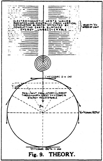
                      Tesla illustrated this himself in an article "THE TRANSMISSION OF ELECTRICAL ENERGY WITHOUT WIRES" on March 5, 1904, which you can find at:
                      Transmission of Electrical Energy Without Wires

                      He used the following illustration to show the difference between electromagnetic radiation (either "Herzian" or longitudinal, btw):

                      The text in the upper part of the picture reads:
                      Electromagnetic Hertz waves radiated horiontally from vertical conductor, slightly affected by conducting Earth surface.
                      ENERGY UNRECOVERABLE
                      Now why is this so important? Because no matter what kind of waves are transmitted from the vertical conductor, with or without a sphere on top, the energy radiates away in all directions and is therefore lost for all but a very small fraction!

                      This same picture is also printed in Eric Dollard's book, with the following comment:
                      Tuks DrippingPedia : Theory Of Wireless Power

                      It can therefore be seen that while the transmission of transverse waves involves the spraying of energy, with its consequent square law diminishment of energy density, and no hope of retrieving the unused energy, the Tesla system involves the direct connection of transmitter and receiver, via the pulsating lines of electric induction. Therefore, the transmitter and receiver are rendered as one apparatus.
                      <snip>


                      So, to sum this up:
                      Yes, longitudinal waves as well as transversal waves are transmitted by your sphere/coil arangement. And yes, you can detect them at some distance and use them to transfer energy over a small distance. The point is that this kind of energy radiaton should be avoided as much as possible, because all energy radiated into space is wasted can cannot be recovered. And the energy gain that Tesla found, and which is why he called his invention the "Magnifying Transmitter", is to be found in the higher order resonance standing wave in/along the "ground" connection between transmitter and receiver.

                      So, the critical component in a magnifying system is the "ground" connection between transmitter and receiver, which should be in higher order resonance and non-radiating. And that is the essential difference between the transmission of energy "trough the air" and Tesla's system.

                      Comment


                      • Originally posted by dR-Green View Post
                        I tried, briefly, to find the resonant spots of my coil last night by using the 555 driver, but I don't think I have it connected right, or I'm going to have to swap resistors because I'm stuck in a narrow frequency range with the resistances I'm using. I'm getting a sort of stretched "h" wave output from the coil, and within the narrow frequency range I've tested the output looks pretty much the same on all frequencies. There are no peaks whatsoever. So I don't know if I've connected it wrong or if I should try different frequencies, I'll find out some more shortly. Otherwise I have a signal generator kit which I bought specifically for this purpose so I'll have to put that together, but I was hoping the circuit I already had being based on the same basic circuit as the signal generator kit could also be used.
                        I'm not sure dR, but I imagine even with a spark gap some things wll need to be adjusted, like the gap itself and the amount of energy put through it. The spark gap setup I used a while ago could be tuned down to just spark a little bit sporadically or it could be continuous and I think more than needed. I'm not saying that spark gaps shouldn't be used just that I'm not going to use one on a device I want to run 24/7. I think they have limitations in some area's like other methods have limitations too.

                        I just ordered my 2nd copy of that book on monday The one I currently have has useless diagrams that looks like someone spilt a pot of ink on the page, just a big black mass Interesting looking device.
                        I just downloaded the book free, But it would take a lot of ink to print it so it's probably cheaper to buy one than print it at home. Dissapointing about the bad picture's, there is a lot of info in the picture's. Much.

                        Oh yeah but there is also lot of info in the high potential lighting section, the second part of the book, "Tesla Effects with High Frequency and High Potential Currents", there is a lot of info in the text, explanations of principals and such. I can't say I've read it all myself. I tend to scan pages for key words and work back and forth to find what I want. The picture's do help to find the parts i want actually. I recommend downloading it to use but a good hard copy would be priceless.

                        Cheers
                        Last edited by Farmhand; 09-08-2011, 12:07 AM.

                        Comment


                        • Thanks for that info lamare, I'll have to take a closer look I'll get back to you on specific points tomorrow after I've had some sleep.

                          @Farmhand: The one I already have is this one

                          Inventions, Researches and Writings of Nikola Tesla: Amazon.co.uk: Thomas Commerford Martin: Books

                          And this is the one that's on its way

                          The Inventions, Researches and Writings of Nikola Tesla, With Special Reference to His Work in Polyphase Currents and High Potential Lighting: Amazon.co.uk: Nikola Tesla, Thomas Commerford Martin: Books

                          Hopefully all the diagrams will be right, I'll soon find out. Definitely keep away from the first one anyway.

                          Yes I don't think I'd be comfortable leaving the spark gap going, at least not without plenty of hours of experience to know it's safe. I'd love to go camping in the local forest with some sort of wireless power reception though

                          Anyway, I've been doing some long due research on the 555 circuit, namely what the capacitor and resistors do, and I believe I'm starting to get somewhere. The ignition coil(s) seems to work best around the 800Hz range while keeping the input below 1 amp, although this low an input will be useless in the longrun probably. Now I'm able to get octaves out of the spark gap again, and I'm even able to use two capacitors (!!) with one coil, which was impossible before, all I got was a hum. I'm still noticing the spark gap sparking when I manually connect the circuit though, but it won't continue automatically at that distance.

                          So through all this I've noticed a couple of things, although I've noticed the bulb thing before, the circuit feels more stable now so it's easier to do tests. Earthing the outer end of the spiral secondary increases the voltage on the inside. The filament bulb connected on the inside of the spiral somehow seems to magnify streamer length by about 3 times, or the wire coming from the bulb appears to be compressing the charge into a smaller point. Testing before the bulb produces small sparks. The bulb casing which is AFTER the filament produces slightly bigger sparks, but the wire connected to the same casing coming away from the bulb produces sparks about 3 times the length of those on the casing itself.

                          Next test: The filament lights between the outside secondary connection and earth. It gets brighter with a fluorescent or CFL connected to the inside with no change to the input, if anything it goes down. 300-400mA input. The lights are brightest at lower inputs. With various spark gap settings input can go up to 1 amp and the filament barely glows. Adding a CFL or fluorescent to the inside is having an effect on the spark gap in that it changes the frequency and it gets more efficient, as if it wants something to work into. Without this thing to work into it for some reason uses more power and produces less light output. Also of note here is that adding the fluorescent or CFL to the inside of the coil causes more energy to appear on the outside, or flow into earth or whatever.

                          Last edited by dR-Green; 09-08-2011, 07:58 AM.
                          http://www.teslascientific.com/

                          "Knowledge is cosmic. It does not evolve or unfold in man. Man unfolds to an awareness of it. He gradually discovers it." - Walter Russell

                          "Once men died for Truth, but now Truth dies at the hands of men." - Manly P. Hall

                          Comment


                          • Hi dR, a lot of the things you describe seem familiar to me, sounds like some of the things that confounded me. I think i have a couple of idea's about what is going on. I've been thnking on it, i'll need to make a couple of simple circuit layout sketches to explain what I mean.

                            I'll gather my thoughts and get back to post it. It just all of a sudden came to me what it could be a combination of, but to just explain it might not work so well.

                            Cheers

                            Comment


                            • Hi dR, I'll try to run through a few things that i think could help.

                              This is the setup below (more or less) I used to get fairly good results with a Spark gap. First question is. Do you have a HV diode on the output of the ignition coil ? The diode is important. If you use two ignition coils they'll both need diode's on the HV output.

                              Second thing is when you connect the outer end of the secondary to ground or lump of metal or the other coil this will change (lower) the freqeuency of the secondary coil, adding a termination to the center end of the secondary will do the same thing. Which is OK.

                              Because this enables us to use a small capacitance connected to the primary, which lowers it's resonant frequency as well, the trick is to match them, but the primary should be at a slightly lower frequency than the secondary if you want to approach the terminal with fluro's and stuff for demo's. The secondary resonant frequency will lower as you near the coil with you're self or an object moreso if the object is grounded, because this increases the effective capacitance of the secondary, I think. As the secondary frequency lowers they become more matched instead of more unmatched in frequency. This is also a consideration if the coil is tuned when you are near it close enough to affect it this way, because when you move away the secondary frequency will rise a bit.

                              The capacitance on the primary also allows for a better coil discharge and charge, more current, better spark. But more capacitance will lower the resonant frequency, so a balance must be met and somewhat planned for or adjusted to. And also why taps are handy on the primary. With you're big primary being matched it should not need to be tapped though I agree. It took me a while.


                              Uploaded with ImageShack.us

                              I think just adjust you're pulsing of the ignition coil and the cap size across it to get the power you want so you get a good spark through the gap by fiddling about till you get them how you think is good. If you find the HV cap seems to fill too slowly at a reasonable input meaning you get a slow but strong spark it might be too big. It pays to experiment a bit there. I think you already know the effects of adjusting you're gap

                              So the other thing is to see the effect of increasing the termination capacitance while the setup is running. you can see that by holding you're hand about a foot or more away from the terminal and slowly moving it in a bit. Remember a load will have a similar effect when you approach the coil terminal with a fluro tube or something it increases the effective capacitance of the secondary and lowers it's frequency. If the primary coil is exactly matched this will throw the coils out of whack with each other. This can be very frustrating. And difficult to counter well.

                              I hope some of this helps, If I repeated stuff I'm sorry. If there is anything I can be more clear on, please just let me know.

                              I forgot what size HV cap you have. I think fairly small is needed but it's hard to tell. It depends.


                              Edit: In this video at starting at 1:00 minute you can see the difference between pulsing the ignition coil starting first at 1:00 mins using the lower frequency then at 1:07 I change to double the frequency to the ignition coil but atill using the same power input. there is a brief moment between when only one coil is on so it's at half power. The higher frequency pulsing of the ignition coil seemed to help a bit with that setup, it wasn't tuned in any real way at all though.

                              AlternateFarmhand1's Channel - YouTube

                              Just thought I would share that as an example.
                              Last edited by Farmhand; 09-08-2011, 01:18 PM.

                              Comment


                              • Hi all, A bit of humor here for a minute and maybe some sense.

                                This looks like OU to me.


                                Uploaded with ImageShack.us

                                Just born. So 1 + 1 = 4 this time. It usually does with goats.

                                I took one male goat added a female goat and now I have 4 goats. Actually I have more, but I only allowed two to breed.

                                If we can separate or mate (join), male and female to multiply or not with animals. Why not with energy or with the componants of electrical energy, ie. magnetic and dialectric. Separate and rejoin to multiply or concentrate/attract, attract from the environment by separation. The animals gather what they need to multiply from the environment.

                                Anyway, the kids are cute. The mother has had seven kids now. And she's not old yet. The chickens are also multiplying.

                                Must be spring time again.

                                Cheers

                                EDIT:

                                Today almost got very Ugly, I almost stood barefoot on this Taipan.


                                Uploaded with ImageShack.us


                                Uploaded with ImageShack.us

                                Taipan - Wikipedia, the free encyclopedia

                                Luckily for me I had a shovel in my hand, it almost got me. One more step without seeing it and I was a goner. Phew. I wouldn't usually kill them, they are protected, but I just reacted. Poor thing. At least my dog will live another day. This one looks about 2 meters long.

                                Humans 1, Serpents 0

                                Which reminds me of this song, because we are all just another brick in the wall.

                                Pink Floyd - Another Brick In The Wall, Part 1 - Live, 1980 - YouTube

                                ,,
                                Last edited by Farmhand; 09-10-2011, 02:19 AM.

                                Comment

                                Working...
                                X