If this is your first visit, be sure to
check out the FAQ by clicking the
link above. You may have to register
before you can post: click the register link above to proceed. To start viewing messages,
select the forum that you want to visit from the selection below.
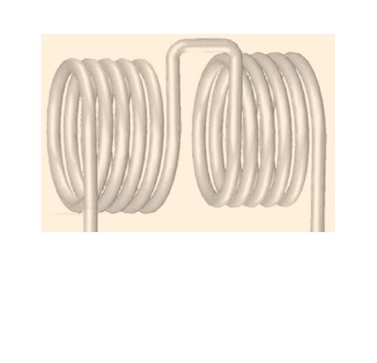
Here's what I think about the opposite wound coils thing.
If the coils are wound like in the attached drawing the primaries pulsed in series
or parallel, then the secondaries should be in phase, and in series they would
double voltage and in parallel they should double current but same voltage.
A similar thing can be achieved by pulsing (using AC too), a pair of ignition
coils or similar maybe resonant coils, in anti parallel, they can be wound the
same way then. There is a web page on it. I'll find it later.
Here he describes a way to use an iron cored coil.
Page 172 IRWNT
"Another way of adapting the iron core to rapid alternations,
or, generally speaking, reducing the frictional losses, is to produce
by continuous magnetization a flow of something like seven
thousand or eight thousand lines per square centimetre through
the core, and then work with weak magnetizing forces and preferably
high frequencies around the point of greatest permeability.
A higher efficiency of conversion and greater output are
obtainable in this manner. I have also employed this principle
in connection with machines in which there is no reversal of
polarity. In these types of machines, as long as there are only
few pole projections, there is no great gain, as the maxima and
minima of magnetization are far from the point of maximum
permeability ; but when the number of the pole projections is
very great, the required rate of change may be obtained, without
the magnetization varying so far as to depart greatly from the
point of maximum permeability, and the gain is considerable."
And here he says if making the coil to do it, then the way it's shown in the diagram
figure 113 is a very good way.
Page 172 IRWNT
"The above described arrangements refer only to the use of
commercial coils as ordinarily constructed. If it is desired to
construct a coil for the express purpose of performing with it
such experiments as I have described, or, generally, rendering it
capable of withstanding the greatest possible difference of potential,
then a construction as indicated in Fig. 113 will be found of
advantage. The coil in this case is formed of two independent
parts which are wound oppositely, the connection between both
being made near the primary. The potential in the middle being
zero, there is not much tendency to jump to the primary and not
much insulation is required. In some cases the middle point
may, however, be connected to the primary or to the ground. In
such a coil the places of greatest difference of potential are far
apart and the coil is capable of withstanding an enormous strain.
The two parts may be movable so as to allow a slight adjustment
of the capacity effect."
The key point being there is two primary coils opposite, to force the 0 volts to
the center tap and potential to the ends. It can be done with two identical
coils as this video shows, they are used in "anti - parallel".
Here's some video from where I ran a small motor from the rectified output of
the receiver, I only pulsed the transmitter at half the resonant frequency for this
experiment, I did it like that just to see the available power plus I don't want to
burn out the little motor.
I think I might construct a transformer like this. I'm not sure what wire exactly
I'll use yet, I've got a few different kinds. I can mount all the formers on the
smaller PVC pipe and use a ferrite core if I want or use the stick. I an use a
spacer between the two sets of formers as well.
I'll be able to put the whole setup inside a larger PVC Tube with screw on
ends and bring the wires out through sealed grommets. Then I can fill it with
transformer oil. I've got 40 liters of it but it needs boiling out.
I figure i can get about 5600 turns of 0.5mm wire on the larger outer formers
which will be the HV secondaries.
And I think I'll use two strands of 1mm wire wound next to each other in
parallel for two layers of 30 turns each on the inner formers. This way I can
use both strands on each primary in parallel and both primaries in parallel.
That should give me with 24 volts input about 2200 volts between each
outside and center or 4400 volts between the two outsides, but if it's in oil
I should be able to use more on it.
EDIT: Correction I should be able to get 4600 turns of 0.5 mm wire in the
secondaries so that's about 1850 volts per side with 24 volts input. I wonder
what frequency I'll be able to use on them. Any hints.
I'm hoping to able to pulse them at 115 Khz at least, hopefully 230 Khz or more.
If I can get 3600 volts at 230 Kz I'll be very happy.
I should be able to get it all into a tube 90mm diameter and 250mm long.
This is what I want to build for charging the primary capacitors on my HV air cored resonant transformers .
Looks like he is using about 300 watts input from the wall. Not sure of the
output it could be as low as 30 watts or even less. It's not really clear what
he's doing there, there is no way of telling if the desk lamp is also powered by
the Tesla coil output or if it is powered by the supply transformer. Looks like
the coils are very close and one is laying down for some reason. I can't tell how the setup is configured.
The big question is how long can it be left running, he seems quick to turn it off.
Probably because of heating mosfets. To be any use a setup needs to be able
to run 24/7 not just in short bursts. Any pair of Tesla coils can do wireless
transmission, it's just a matter of building them to be able to run continuously
and with a usable output.
Not much use if it's running lights and it can only be turned on for 10 minutes.
I prefer if people when making a technical video explained a bit of what they
are doing, he has some info in the video but not enough to satisfy my
curiosity.
Oh yeah I haven't got around to experimenting with the spherical antenna yet.
Experiment 4
Inserted a metallic plate between two Tesla Coils - the receiving Tesla coil is still powering a 220V 60W lamp much over voltaged. Plate is connected to a 220V 40W lamp. Other side of lamp is connected to a 5 meter long wire just laying on the floor unconnected.
The length of the wire determines the brightness as the wire has capacitance and inductance and it acts as a "choke" for the rapidly varying field potential in order to create a high enough current in the filament to light it. Connecting it to ground reveals the potential present by the arcing and brightens the lamp though diminishes the brightness of the lamp connected to the second coil as the field effect is reduced
Demonstration of how a tuned Tesla Coil emits rapidly varying impulses akin to electrostatic generators. While electrostatic generators simply build up a constant static charge, a Tesla Coil at it's 1/4 Wave peak output builds up an average one sign charge even if it is rapidly varying, respect to the ambient ground.
This simple yet misunderstood concept distinguishes the Tesla Coil air core high tension transformer from any other standard "lumped" transformer theory.
The thin aluminum leaf placed on the top load is charged with the same sign charge as the top, hence it is repelled as soon as, or near, resonance.
The term "pseudo electrostatic" means that the output of the coil is not a mere "static" (constant) output, but rather oscillates at the resonant frequency of the coil and is characterized by a biased potential respect to ground.
The reason for this effect is connected to the coil's self capacitance and self inductance which must be considered individually between every adjacent turn of the coil and globally, considering the high frequency operation. We can say that every turn of the coil behaves as an individual small LC circuit connected in series with the next, but also coupled due to proximity
“Signs and symbols rule the world, not words nor laws.” -Confucius.
Hi MonsieurM, Please don't take this the wrong way, but I'm too busy.
If it's plugged into the wall I'm not really interested, sorry. I am busy
experimenting with my own direction so I won't be browsing any channels.
I refuse take any notice of what people say who profess to have some fantastic
device but do not show it.
If I want to light 240 bulbs at less than unity from two feet I just use an
inverter and a battery. I'm not chasing free energy, I'm experimenting and
researching.
I don't see what I'm supposed to get from the video. He had the plate only
inches from the Tesla coil. If he was transmitting over 50 meters through a
single wire or the ground and powering the setup from a battery I would be
interested. As far as I can tell he is using power from the wall I power my
experiments from the sun. I power my lights from the sun too mainly.
Looks like he is using about 300 watts input from the wall. Not sure of the
output it could be as low as 30 watts or even less. It's not really clear what
he's doing there, there is no way of telling if the desk lamp is also powered by
the Tesla coil output or if it is powered by the supply transformer. Looks like
the coils are very close and one is laying down for some reason. I can't tell how the setup is configured.
The big question is how long can it be left running, he seems quick to turn it off.
Probably because of heating mosfets. To be any use a setup needs to be able
to run 24/7 not just in short bursts. Any pair of Tesla coils can do wireless
transmission, it's just a matter of building them to be able to run continuously
and with a usable output.
Not much use if it's running lights and it can only be turned on for 10 minutes.
I prefer if people when making a technical video explained a bit of what they
are doing, he has some info in the video but not enough to satisfy my
curiosity.
Oh yeah I haven't got around to experimenting with the spherical antenna yet.
Cheers
most of those tests are simply near field rf or magnetic induction. tesla said in the court case his device was neither. In order to get proper test results it seems to me that a person has to get a minimum of 1.25 wavelengths away from the transmitter and ideally transmit through the ground which is where they should get the 292fps speed.
I think I might construct a transformer like this. I'm not sure what wire exactly
I'll use yet, I've got a few different kinds. I can mount all the formers on the
smaller PVC pipe and use a ferrite core if I want or use the stick. I an use a
spacer between the two sets of formers as well.
I'll be able to put the whole setup inside a larger PVC Tube with screw on
ends and bring the wires out through sealed grommets. Then I can fill it with
transformer oil. I've got 40 liters of it but it needs boiling out.
I figure i can get about 5600 turns of 0.5mm wire on the larger outer formers
which will be the HV secondaries.
And I think I'll use two strands of 1mm wire wound next to each other in
parallel for two layers of 30 turns each on the inner formers. This way I can
use both strands on each primary in parallel and both primaries in parallel.
That should give me with 24 volts input about 2200 volts between each
outside and center or 4400 volts between the two outsides, but if it's in oil
I should be able to use more on it.
EDIT: Correction I should be able to get 4600 turns of 0.5 mm wire in the
secondaries so that's about 1850 volts per side with 24 volts input. I wonder
what frequency I'll be able to use on them. Any hints.
I'm hoping to able to pulse them at 115 Khz at least, hopefully 230 Khz or more.
If I can get 3600 volts at 230 Kz I'll be very happy.
I should be able to get it all into a tube 90mm diameter and 250mm long.
This is what I want to build for charging the primary capacitors on my HV air cored resonant transformers .
why wouldnt you put the secondary in the center and primar on the outside?
Here it is so far. The Secondary measures 61.6 mH and 22.8 ohms. And so far
is 12.5 layers with 136 turns per layer, so about 1700 turns, with home made
bees wax paper between each layer. The resonant frequency with 1 pF works
out by the calculator to be just right at 640 Khz.
The primary is about 0.1 ohms and 0.018 mH. It's 20 turns of 10 amp auto
wire so far, the way it is built the primaries can be changed.
I think I'll try it like this, I just need to wind the other secondary.
Good question Kokomo, This way the primaries are near the lower voltage
windings of the secondary, the higher voltage is towards the outer diameter
of the coil and the HV is taken off at the ends in my design away from the
primary leads. The two inner ends of the secondaries near the primary leads
are 0 volts or about. This way it could be used with HV input too.
Comment