Announcement

Collapse
No announcement yet.

Tesla's Magnifying Transmitter "Replications"

Collapse
X
 
  • Filter
  • Time
  • Show
Clear All
new posts

  • #46
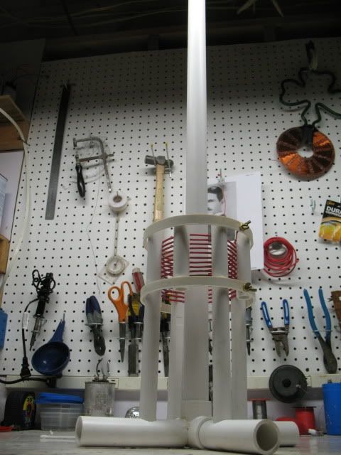
    Hi Guys, I'll link a few building picture's here for those who may be putting together some setups, I just joined some drainge tube and discovered a trick so I'll put any construction picture's here and edit more in later maybe.

    I use quick and practical methods that do not require special tools wherever possible.

    First the simplest way I've found to get a straight square line around a pipe or cylinder is to use a square piece of paper or similar, wrap it around the pipe and line up the edges while it is all tightly wrapped if the paper is square or rectangle the end makes a perfecly square "level" line around the pipe, just draw around it, this is helpfull for cutting the pipe and for marking start and end points and whatnot.

    Like this.
    https://skydrive.live.com/?cid=32a91...1247&sc=photos

    Here's the coil winding video links.
    Part 1
    YouTube - ‪AlternateFarmhand1's Channel‬‏

    Part 2
    YouTube - ‪AlternateFarmhand1's Channel‬‏

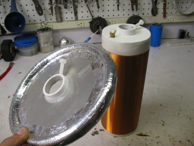
    For the toroid terminal so far I just use slotted drainage pipe, I found if I cut the end down to the first slot on both ends I can fit them one inside the other by squasing one in and cliping the lip of one into the groove of the other.

    https://skydrive.live.com/?cid=32a91...1293&sc=photos

    Makes a good join.
    https://skydrive.live.com/?cid=32a91...1295&sc=photos

    I just taped the joins for now
    https://skydrive.live.com/?cid=32a91...1296&sc=photos

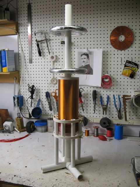
    These ended up rough with not a smooth surface I need better materials. But adding the second torus to the terminal decreases the resonant frequency about 50 Khz to 442 Khz it was about 492 khz so maybe I can work out the capacity from that roughly using the coil design app.

    Increased capacity terminal.
    https://skydrive.live.com/?cid=32a91...1297&sc=photos

    Last edited by Farmhand; 07-07-2011, 07:05 PM.

    Comment


    • #47
      Hi Farmhand. I like your idea to cut a straight piece of pipe, I've had trouble with that myself. I'm not attempting the things discussed in this thread at the moment but having recently built a Tesla coil I thought I'd share how I did it in case something might solve a problem or give ideas to someone out there. The coil I've made is on a smaller scale than this, using 2" diameter PVC downpipe. For the topload toroid I used 2" diameter pipe insulation (that grey foam stuff), cut V shaped notches out of it with a knife to be able to fold it into a toroid small enough to fit the 2" diameter secondary, held it together with some duct tape and then taped it up real good with aluminium foil tape. Each piece of which conveniently NOT being insulated from every other piece, so job done there. I was foreseeing problems as one might imagine

      For a backup topload I grabbed a couple of plastic toilet cistern floats

      On the top and bottom of the PVC pipe, as a stand basically, I used what's called a boss connect or boss adapter, looks similar to this

      http://www.allplumbingsupplies.co.uk..._2s402_img.jpg

      The ones I have have a small notch on one side, so I made a hole in a piece of 18mm thick MDF, cut a small notch in it with a hacksaw, and place the boss connect down into the hole. There is a rubber seal inside the boss connect, so when you put the pipe the secondary is wound on into it it's held in place tightly. The 18mm thickness of the MDF and the correct sized hole is enough to support the coil. Another boss connect goes on the top of the pipe, and the pipe insulation toroid along with a thick layer of tape fits tightly onto it.

      I haven't decided how to finish it off yet but my temporary solution is I've scraped the insulation off the end of the secondary wire, held it on the boss connect and then push the toroid down over it to make the connection.

      I'll take some pictures and post them soon to make it all a bit easier to understand.
      http://www.teslascientific.com/

      "Knowledge is cosmic. It does not evolve or unfold in man. Man unfolds to an awareness of it. He gradually discovers it." - Walter Russell

      "Once men died for Truth, but now Truth dies at the hands of men." - Manly P. Hall

      Comment


      • #48
        I've just learned that I am being visited in a few days by a relative who works in the coal export buisness, he has some degree or other and is an industrial chemist though i think he mainly works in a consulting capacity now. Anyway I would like nothing better than to have him leave with the image of some Tesla Tech invading his head.

        Maybe he will see a very crude model of the instrument of his industries eventual demise.

        So to that end I am determined to have these coils back together to show him at least something. I'll be preparing some papers for him to take away as well. So i will be very busy. I won't have time to make the SG 3525 pulse generator drawing till next week.

        Hopefully some overnight modifications will improve performance a bit.

        It was funny when I showed some other relatives recently they were not really very impressed until I held a 2 foot fluro up near the toroid and it lit up, then I actually heard them gasp and seen them furrow thier brows. After that they were interested. Especially the youngsters. It was hard for them to understand how I could hold a piece of wire which was sustaining an HV arc to the terminal. Difficult to explain in 5 minutes. But I tried.

        Cheers

        Comment


        • #49
          Originally posted by dR-Green View Post
          Hi Farmhand. I like your idea to cut a straight piece of pipe, I've had trouble with that myself. I'm not attempting the things discussed in this thread at the moment but having recently built a Tesla coil I thought I'd share how I did it in case something might solve a problem or give ideas to someone out there. The coil I've made is on a smaller scale than this, using 2" diameter PVC downpipe. For the topload toroid I used 2" diameter pipe insulation (that grey foam stuff), cut V shaped notches out of it with a knife to be able to fold it into a toroid small enough to fit the 2" diameter secondary, held it together with some duct tape and then taped it up real good with aluminium foil tape. Each piece of which conveniently NOT being insulated from every other piece, so job done there. I was foreseeing problems as one might imagine

          For a backup topload I grabbed a couple of plastic toilet cistern floats

          On the top and bottom of the PVC pipe, as a stand basically, I used what's called a boss connect or boss adapter, looks similar to this

          http://www.allplumbingsupplies.co.uk..._2s402_img.jpg

          The ones I have have a small notch on one side, so I made a hole in a piece of 18mm thick MDF, cut a small notch in it with a hacksaw, and place the boss connect down into the hole. There is a rubber seal inside the boss connect, so when you put the pipe the secondary is wound on into it it's held in place tightly. The 18mm thickness of the MDF and the correct sized hole is enough to support the coil. Another boss connect goes on the top of the pipe, and the pipe insulation toroid along with a thick layer of tape fits tightly onto it.

          I haven't decided how to finish it off yet but my temporary solution is I've scraped the insulation off the end of the secondary wire, held it on the boss connect and then push the toroid down over it to make the connection.

          I'll take some pictures and post them soon to make it all a bit easier to understand.
          Yes very good thanks, I didn't think of that, sounds like a good method. The connection at the top is a difficult one so I just sit the aluminium disc I use in the middle of the toroid on top of the bared wire for now I hope to find some ways to make all these little things better. All idea's are good if they work.

          I wish I could calculate the approximate values of the different ways of making the toroids. I wonder if it is better to exclude the air from the torus or not.

          Comment


          • #50
            I wish I could calculate the approximate values of the different ways of making the toroids. I wonder if it is better to exclude the air from the torus or not.
            I posted this in the other thread, you may have missed it. There are lots of other good calculations on this site too. Select toploads.

            DeepFriedNeon - Tesla Coils


            As far as construction goes, i have lots of tools (but I still want more ) however, one could do a lot with simple hand tools if they know what they are doing. Like you guys, I like working with pvc for these coils. You can get real creative with the stuff and you can stick it together any which way with some pvc glue as long as you give it enough surface area to glue to. Brass screws with wingnuts work good for connection points. To connect the toriod i like to take a flat strip of copper soldered right at the end of the coil and run it up to the top of the form and bend it over 90 degrees to make a flat surface for toroids to sit on.

            I always try to make my designs as variable as possible. Everything must be able to tune. If you cant adjust things you will never know where it works best at. One method i like for this is using a straight pvc pipe up the center of the coils that everything else can slide on. That way i can adjust the coupling beteeen coils by sliding them up or down as well as the toroids. It also makes it easy to swap out with different coils or toroids. Here is one example. This is the primary, stand, and center pvc tube i have been referring to.


            And this is how i set up my coils and toroids to work with the center tube. I use the nylon screws to clamp the toroid or coil in the position along the tube where ever i desire it at. That is the bottom of the coil, you can see the brass screw and wing nut i use to connect my ground.


            And here it is all put together. Little tip for you, see the toriods floating above the coil. They dont need to be connected to add capacitance. You know how to use inductance to tune already. But with this basic design concept you can use capacitance to tune your coil by moving the toroids closer or farther from the top of the coil or other toroid below.

            Comment


            • #51
              Hi Cody, Excelent design and tips, I especially like the suspended toroid, I did kinda realise that it wouldn't need to be connected to the first but wasn't sure really and had trouble working out how to go about it.

              As you might have seen my second test was just a bit better than the first.

              The function generator is pretty neat even though it's a cheapie it seems to work. Very satisfying to sweep the coil and find its frequency so easily.

              What I have worked out is that the 5 turn primary I estimated by the coil design app is about right for a small capacitance top terminal "original one" because with 5 turns the primary inductance is just a bit more than the secondary somehow, maybe mutual inductance not sure. But the effect is that I could tune it for good output where with more turns I can't.

              So it appears to me that by adjusting the primary turns in the coil design app. until the primary inductance is just a bit greater than the secondary means the primary will have a lower resonant frequency than the secondary without the extra capacitance of the top terminal, then the top terminal lowers the secondary's resonant frequency to be closer to the primary, but this doesn't take into account the primary capacitance. So i'm not sure how it worked so well for me.

              I tried the 17 turn primary with the turns next to each other and that didn't work, I assume because that increased the primary inductance a lot.

              So after all that I think I will make a second 5 turn coil for the receiver and the receiver variable inductor, then see what i've got, and play with the top terminal from there. I have a feeling my terminals are a good size just the surface is too rough and they need to be adjustable in height.

              Thanks for the excelent idea's, I'm very glad you've come to help.

              Cheers

              Comment


              • #52
                Ok so I'm thinking of trying this arrangement of adjustables,
                https://skydrive.live.com/?cid=32a91...1299&sc=photos

                So in practice the variable primary inductor would look like this but with more turns wound the correct way and mounted. I'll replace this picture when I get it done properly.
                https://skydrive.live.com/?cid=32a91...1298&sc=photos

                The only other way I can think of is to use a wiper like a variac then it could be remain air cored and also fully adjustable down to negligable.

                My circuit doesn't look exactly like any of Nikola's on page 10 of his work on alternating currents but I'm using DC I guess it needs to be.
                I'm thinking going by those diagrams of his, my variable primary inductor should be after the primary DC wise on the negative line at bottom.

                I'll try it how my sketch is first with a full layer of turns, about 33 turns. The core piece is iron powder.

                Nikola Tesla on his work with ... - Google Books

                Then with an adjustable Terminal height as well I should get a result.

                I hope.

                Comment


                • #53
                  I see in diagram 10 and 11 of figure 5 on page 10 of Nikola's work on alternating currents the secondaries have an "air gap" "Sparkless gap" and a capacitor respectively, that is interesting.
                  Nikola Tesla on his work with ... - Google Books

                  He also talks of a thick wire over the top of one of his alternators for harmonics and a capacitor on the primary of his alternator to increase the current through it. Way to go.

                  Comment


                  • #54
                    Just stumbled across this pdf on Tesla Wireless by Steve Jackson:
                    http://ieeesb.mcmaster.ca/~hamilton/...elessPower.pdf

                    More on this:

                    OS:Tesla, Meyl, and Jackson's Wireless Aetheric Power Transmission - PESWiki

                    Complete building instructions:
                    http://freeenergynews.com/Directory/...pr-21-2011.pdf


                    Update: couldn't resist to reply to Steve's little challenge:


                    Hi Steve,

                    Just found your stuff on Tesla Wireless and I'm afraid I will have to wear my De-Bunker hat on this one, even though I am a fan of Tesla and firmly reject Einstein's relativity theory:
                    http://www.energeticforum.com/renewa...ain-wrong.html

                    But to your little challenge:
                    http://freeenergynews.com/Directory/...pr-21-2011.pdf

                    Well, here is the hurdle that De-Bunker Papers must leap:

                    Explain the Elephants in the Room, some of which are:

                    1. Transmission of non-negligible levels of power over 1 - 100 meters
                    2. Operation inside a verified Faraday cage (where a radio plays only static)
                    3. Absence of 1/rē reduction of received power
                    4. Communication link from Receivers back to Transmitter
                    5. Communication link between Receivers

                    If you are a De-Bunker, and you cannot explain these Elephants in the Room, then please refrain from commenting on these significant and verifiable phenomena.

                    You see, the explanation of these Elephants is actually very simple. The Tesla Wireless System does not operate by means of transmission of energy trough the air (a/o vacuum). Not with longitudinal (scalar) waves and also not with EM waves. It is essentially a one-wire transmission system that uses the earth as a conductor. Tesla said so himself:

                    "The True Wireless" by Nikola Tesla
                    While the spontaneous success of my lecture was due to spectacular features, its chief import was in showing that all kinds of devices could be operated thru a single wire without return. This was the initial step in the evolution of my wireless system. The idea presented itself to me that it might be possible, under observance of proper conditions of resonance, to transmit electric energy thru the earth, thus dispensing with all artificial conductors.

                    Eric Dollard explains this very well in his books, which you can find in my archive:
                    Directory contents of /pdf/Eric_Dollard_Document_Collection/

                    I am working on digitizing these, starting with "Theory of Wireless Power":
                    Tuks DrippingPedia : Theory Of Wireless Power

                    A quote from that one:

                    The system of transmission and reception of electric energy without the employment of connecting wires, or waveguides, as conceived by Dr. Tesla IS NOT the propagation of any type of electromagnetic wave, nor is it the excitation of the earth-ionosphere waveguide. Tesla's system employes resonant actions along lines, or rays, of ELECTRIC INDUCTION, these lines standing between the transmitter and the receiver, figure (3). The appar*atus for establishing these lines of induction is called the Tesla Magni*fying Transmitter (T.M.T.). The T.M.T. is a system of resonant transformers harmonically balanced to the electric condition of the earth. The mono-polar nature of the T.M.T. induction facilitates the ease of transmission and reception that this apparatus exhibits. These lines of induction established by the T.M.T. are drawn into the high inductivity of the earth's interior; despite the conductivity of the surface, which would screen electro-magnetic waves.

                    [...]

                    The dielectric induction thru the interior of the earth communicates the energy from the transmitter to the receiver as shown by figure (4). The unused portion of energy is reflected back to the transmitter more or less completely. Operating this energy reciprication between transmitter and receiver at the natural period and waveshape of the earth's own energy pulsation rate greatly overcomes the effect of distance, hence no significant loss of energy is apperent. Thus a standing wave of induction energy exists between the transmitter and receiver, or what can be called transponders, pulsating at one of the earth s natural harmonics. If the phase angle of the earth pulsation frequency lags the phase angle of the pulsating frequency energy is abstracted from the earth's supply of energy and delivered as "free energy" to the transponders.

                    It can therefore be seen that while the transmission of transverse waves involves the spraying of energy, with its consequent square law diminishment of energy density, and no hope of retrieving the unused energy, the Tesla system involves the direct connection of transmitter and receiver, via the pulsating lines of electric induction. Therefore, the transmitter and receiver are rendered as one apparatus.
                    c) Operating principles of the T.M.T.

                    Because the energy is propagated thru the "ground" the question exists as to how to ground the apparatus, that is, how to establish an electric reference point, since the so called ground is now the hot terminal of the transponders, and therefore is incapable of also serving as an electric reference point. Here exists the singular feature of the Tesla O.C. tran*sformer in that the distributed mutual inductance and odd function resonance work to establish a virtual ground. This fundamental principle of virtual grounding is also to be found in the Tesla Tele-geodynamic Oscillator (T.G.O.) which serves as a mechanical analog to the T.M.T. The principle behind this is the geometrical reconfiguration of the fund*amental components of energy, the kinetic and potential, this reconfiguration resulting in the separation of cause and effect in not only time but also in space. The result hereof is the circumvention of the Newtonian laws of action and reaction. This allows for the production of heretofore unexplored phenomena.

                    Hence, the T.M.T. as well as the T.G.O. is capable of transmitting vibrations by virtue of the fact that it is SELF REFERENCING, thereby not requiring any ground, that is, no solid backing from which to push against. This relates to the saying "Give me a fulcrum and I will move the earth". Tesla found this fulcrum and moved the earth; both mechanically, producing a local earthquake in New York City; and electrically, producing a stand*ing lightning discharge at Colorado Springs (and possibly lightning else*where on the planet).
                    Key element of Dollard's analysis:

                    Because the energy is propagated thru the "ground" the question exists as to how to ground the apparatus, that is, how to establish an electric reference point, since the so called ground is now the hot terminal of the transponders, and therefore is incapable of also serving as an electric reference point.
                    So, to make a long story short, the energy is transmitted back and forth between two resonating coils along the one wire connecting your receiver to your transmitter, which acts like a wave guide. And this is also why you can transfer lots of energy along the wire, why you can operate it inside a Faraday cage, why you don't see 1/rē reduction of received power, why there is a communication link between transmitter and receiver [along the wire/wave guide] and why there is a communication link between receivers which are connected with the sime kind of wire/wave guide.

                    In other words: no longitudinal/scalar waves here, just one wire energy transmission.

                    Update: I meant: no longitudinal waves should be present between the transmitter spheres, cause the coil base is supposed to be the hot terminal. This is discussed and explained in later posts in this thread.
                    Last edited by lamare; 07-13-2011, 09:37 PM.

                    Comment


                    • #55
                      What I have worked out is that the 5 turn primary I estimated by the coil design app is about right for a small capacitance top terminal "original one" because with 5 turns the primary inductance is just a bit more than the secondary somehow, maybe mutual inductance not sure. But the effect is that I could tune it for good output where with more turns I can't.

                      So it appears to me that by adjusting the primary turns in the coil design app. until the primary inductance is just a bit greater than the secondary means the primary will have a lower resonant frequency than the secondary without the extra capacitance of the top terminal, then the top terminal lowers the secondary's resonant frequency to be closer to the primary, but this doesn't take into account the primary capacitance. So i'm not sure how it worked so well for me.

                      I tried the 17 turn primary with the turns next to each other and that didn't work, I assume because that increased the primary inductance a lot.
                      I think its great to test the primary with different number of turns, but i have a question. Have you been playing with the coupling between the primary and secondary yet with your different number of turns? General rule of thumb ive come to the conclusion of: Transmitter likes to have the tightest coupling possible without causing flashover between primary and secondary. With these low power coils you usually dont have to worry about flashover. You have probably noticed that the photos ive been showing have not been magnifier designs. That is because i cant get a tight enough coupling with them at low power. Its not uncommon for me to have my primary half way up the secondary to get the tightest coupling possible on the transmitter. So make sure to play with that before you draw any conclusions about how many turns work better. The reciever on the other hand likes a low coupling. The coupling on the coils changes the resonant frequency of the secondary so adjustments must be made to get them both in tune.

                      Comment


                      • #56
                        Originally posted by cody View Post
                        I think its great to test the primary with different number of turns, but i have a question. Have you been playing with the coupling between the primary and secondary yet with your different number of turns? General rule of thumb ive come to the conclusion of: Transmitter likes to have the tightest coupling possible without causing flashover between primary and secondary. With these low power coils you usually dont have to worry about flashover. You have probably noticed that the photos ive been showing have not been magnifier designs. That is because i cant get a tight enough coupling with them at low power. Its not uncommon for me to have my primary half way up the secondary to get the tightest coupling possible on the transmitter. So make sure to play with that before you draw any conclusions about how many turns work better. The reciever on the other hand likes a low coupling. The coupling on the coils changes the resonant frequency of the secondary so adjustments must be made to get them both in tune.
                        Yes I'm just finding that out now, I have primaries all over the place, I'm having a great time. Everything will be movable when I'm finished and I'll have two sets of primaries too.

                        I see some patterns I think.

                        Thanks

                        Comment


                        • #57
                          Originally posted by cody View Post


                          I'm speechless. This post went like a laser straight to the back of my brain and woke up memories I didn't have before. Thank you.

                          Comment


                          • #58
                            Hi Guys, good progress for me, Ive made an big improvement to the energy transfer between the two and I've reduced the input a fair bit too uses about 4 watts, now I get 13 volts average at the receiver output while running the two LED's through a 270 ohm resister, they are full brightness If I light a fluro wirelessly from the receiver as well the voltage over the LED's drops to 11.5 volts.

                            Changes I made mean I now have on the transmitter primary circuit a variable charging inductor with a variable capacitance 5.2nf to 6.5nf and the 17 turn primary with turns adjacent. Adjustable inuctance on the secondary.

                            The receiving circuit is identical except for the only cap is a 680uf across the DC of the bridge. I haven't made any change's to the top termnals yet. Still running at 490 Khz.

                            The problem though is no more sparks, I can't get it to use enough power now.

                            Cheers
                            Last edited by Farmhand; 07-09-2011, 05:20 AM.

                            Comment


                            • #59
                              Originally posted by lamare View Post
                              Just stumbled across this pdf on Tesla Wireless by Steve Jackson:
                              http://ieeesb.mcmaster.ca/~hamilton/...elessPower.pdf

                              More on this:

                              OS:Tesla, Meyl, and Jackson's Wireless Aetheric Power Transmission - PESWiki

                              Complete building instructions:
                              http://freeenergynews.com/Directory/...pr-21-2011.pdf


                              Update: couldn't resist to reply to Steve's little challenge:


                              Hi Steve,

                              Just found your stuff on Tesla Wireless and I'm afraid I will have to wear my De-Bunker hat on this one, even though I am a fan of Tesla and firmly reject Einstein's relativity theory:
                              http://www.energeticforum.com/renewa...ain-wrong.html

                              But to your little challenge:
                              http://freeenergynews.com/Directory/...pr-21-2011.pdf


                              You see, the explanation of these Elephants is actually very simple. The Tesla Wireless System does not operate by means of transmission of energy trough the air (a/o vacuum). Not with longitudinal (scalar) waves and also not with EM waves. It is essentially a one-wire transmission system that uses the earth as a conductor. Tesla said so himself:

                              "The True Wireless" by Nikola Tesla


                              Eric Dollard explains this very well in his books, which you can find in my archive:
                              Directory contents of /pdf/Eric_Dollard_Document_Collection/

                              I am working on digitizing these, starting with "Theory of Wireless Power":
                              Tuks DrippingPedia : Theory Of Wireless Power

                              A quote from that one:


                              Key element of Dollard's analysis:


                              So, to make a long story short, the energy is transmitted back and forth between two resonating coils along the one wire connecting your receiver to your transmitter, which acts like a wave guide. And this is also why you can transfer lots of energy along the wire, why you can operate it inside a Faraday cage, why you don't see 1/rē reduction of received power, why there is a communication link between transmitter and receiver [along the wire/wave guide] and why there is a communication link between receivers which are connected with the sime kind of wire/wave guide.

                              In other words: no longitudinal/scalar waves here, just one wire energy transmission.
                              Hi lamare, I was wondering since you are an Electrical Engineer could you tell me the result if two large Tesla Magnifying Transmitters were built as a pair, transmitter-receiver and for some crazy reason they were built only say 100 miles from each other and they worked as described by you in you're last post, then for some other crazy reason the earth connections were disconnected and a very large diameter conductive cable was was connected between the earth connections ?

                              Would they work in that configuration to transmit energy to each other when re-tuned ?

                              And what would be the nature of that energy ?

                              And would the cable between the earth connections act as a waveguide ?

                              Would this be considered a single conductor transmission or a two conductor transmission ?

                              Going back to when it is connected actually through the earth is it not a single conductor transmission ?

                              Or is it a double conductor transmission ?

                              Does a Magnifying Transmitter transmitt AC power ?

                              I thought both conductors were "Hot" with AC power.

                              Tesla says Electromagnetic wave's can be got from his system and he was talking about a Magnifying Transmitter, he conceived it , he invented it and he built it, he said these words below in a Court I believe under Oath. I won't waste my time responding to any more of this talk. It is pure conjecture as far as I can tell. I can't stop people from posting but I just will not respond.

                              Tesla's own words.
                              https://skydrive.live.com/?cid=32a91...1300&sc=photos

                              Cheers

                              P.S. lamare three of you're first 5 links are blank for me too. Just blank page's.
                              Last edited by Farmhand; 07-09-2011, 05:55 AM.

                              Comment


                              • #60
                                It is my opinion that if the correct frequencies are used any of these wireless technologies of Tesla's will work and they will all work in a very similar way, the system is based on his resonant transformers, but they can be used the "wrong way as well" I do agree. I don't understand the need for all the confusing lingo. I can see how it works without the words.

                                Lamare I may have missunderstood the meaning of you're post, and if so I truely appologise, I very much appreciate the help you give us all it's priceless, and you have helped me a lot with my experiments as many others have too.

                                I mean no offence it's just all a bit much take in.

                                Anyway please take no offence to my post, I just like to clarify things if I can.

                                I was a bit confused by the post to tell the truth. I've had a big night.

                                Cheers

                                Comment

                                Working...
                                X