Announcement

Collapse
No announcement yet.

Tesla's Magnifying Transmitter "Replications"

Collapse
X
 
  • Filter
  • Time
  • Show
Clear All
new posts

  • #76
    Monsieur, I think a tennis ball sized sherical helical antenna will be just the right size for the second receiver or maybe just a bit bigger I'll get onto to that now too which will be very interesting to experiment with.

    Might need to adjust up it's own frequency for that one to work from a higher harmonic if there is such a thing.

    I need to get a big long pipe into the ground somehow. So I can fill it with water.

    I made a drawing for a tree coil too' I'll link it in you're Tree collector thread soon as finish it. Basically a Tesla coil wound on a former around a tree with a toroid terminal too. If it was built right it could be placed over a fast growing tree and secured allowing growth then when the tree got too big it could be cut down and used and the coil placed over another tree. Or it could be wound on an established tree too of course. I think I will try it some how.

    Cheers

    Comment


    • #77
      Originally posted by Farmhand View Post
      Again I wasn't actually trying to compare a rifle or a bullet to a wire.

      I was using the example only to explain that things can be understood to a degree without being too complicated.

      :
      I got that.

      What I meant to say is that up to a certain degree, you can describe electro-magnetism using basically the same things as used in hydraulics. Some "thing", a fluid, flows trough some other "thing", a tube or water hose, a pump, etc. And actually 99% of electrical engineering uses this hydraulic analogy, where you can safely neglect the fact that underneath the surface, everything is really a wave (pattern), a very dynamic system.

      And yes, you are right, you can also explain wave dynamics such that they can be understood to a degree without being too complicated, but only once you completely understand what is going on yourself.

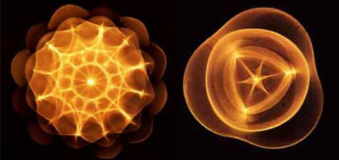
      What is very confusing with the current theory and thus the accompaning vizualisations is that we have been taught the electric field, the magnetic field and the gravitation field are three completely separate phenomena, which are connected in mysterious ways. In actual fact, they are not. This cymatic picture has told me very much:


      You see some clear structure being formed as a result of just one phenomenon: sound waves in a liquid. If you imagine the little ball in the middle of the left picture being the earth and you know that the highlighted area's that form the structure in the cymatic picture are some kind of grains of some kind of material, it is clear that gravity must be a result of ether waves and not something mysterious. Of course, most of the structure is invisible in the real world, because you can only "see" the structure because of the grains in the liquid, but I am convinced the same kind of structure as seen on the picture actually surrounds the earth in the ether.

      Finally, one comes to the following conclusion:
      1. The gravity field is the pressure-variation of the ether
      2. The electric field is the speed of the uni-directional movement of the ether
      3. The magnetic field is the speed of the rotational movement of the ether

      Comment


      • #78
        Originally posted by 7imix View Post
        Hmm, I wonder if propagating longitudinal waves through the conductor and in to the air has to do with turning the area around the transmitter into a plasma? Would the double layer of charge separation around the transmitter make the entire region inside into a homogenous medium, even though it contains solid and air components?

        I visualize a plasma sphere or bubble around the transmitter which is oscillating as a whole. The entire bubble wobbles radially outwards and then back inwards at the resonant frequency and the size of the plasma bubble is determined by the distance the energy can travel at this frequency before turning around.
        Let me just think out loud a bit:

        I don't think you should think in terms of plasma and charge on this level, because the notion of charge is coupled to the so-called "charge carrier" which is some kind of particle. A plasma also consists of particles, just in a different state, whereby the smaller particles that make up the atoms are separated, it consists of freely moving atom nuclei (ions) and electrons.

        However, fundamentally, particles are some kind of wave existing in the ether. So, fundamentally, particles are a result of some kind of movement of/in the ether. And the same thing goes for what is called "transversal EM waves", because these are also particles, just at a different frequency. This only means that the interaction between "transversal EM waves" with "real" particles is different because of the huge difference in frequency and wavelenghts, if they interact at all, because they can be superimposed on one another, which is a pretty fundamental characteristic of waves. And I think this is why we perceive them as completely different phenomena. But in actual fact, they are one and the same, only the scale/wavelengths are different.

        So, charge is not a fundamental concept in ether physics. It is an attribute of a certain kind of wave pattern in the ether, but not a fundamental property of the ether itself.

        And since particles, from the infinitely big to the infinitely small, are essentially some kind of "things" that exists in the ether, the ether itself is not composed out of particles, or at least the *kind* *of* particles that exist in the physical reality we are aware of. In other words: the ether is the fundamental fabric of what we perceive as physical reality and therefore exists out of our perception of physical reality. It is something completely different than everything we know of. All we really know about it is that it has the necessary properties to be able to cause waves and particles to exist. So, all we know of the ether are it's properties in terms that describe the waves that exist in it. And therefore, you should be able to explain everything in physical reality in terms of the fields that exist in the ether, which are the fundamental causes for particles to exist and not the other way around.

        So, while the notion of charge and particles is very useful to explain low frequency stuff and phenomena, with these kinds of RF phenomena, they are only adding to the confusion.
        Last edited by lamare; 07-10-2011, 04:13 PM.

        Comment


        • #79
          Originally posted by lamare View Post
          So, charge is not a fundamental concept in ether physics. It is an attribute of a certain kind of wave pattern in the ether, but not a fundamental property of the ether itself.
          This makes sense.

          Comment


          • #80
            I don't know if this would be useful to you farmhand but i found this website interesting, talks about simulating tesla coils:

            Modelling an actual TC

            I have found that computer simulations represent Tesla Coil behaviour well and give results which are remarkably close to actual measurements performed on real systems. The key to achieving accurate results is to specify the system as accurately as possible in the initial schematic. You must include winding resistances and stray capacitances etc. If these are not included the simulator cannot take them into account, and the results will be inaccurate.

            When simulating a Tesla Coil system I break the system down into two circuits. The first one is the charging circuit, which is simulated with a large step time (100us.) The tank capacitor is charged as normal but discharges into the low resistance of the spark gap model (switch). The large time step can be used here because there is no oscillatory ringdown when the spark gap fires. This allows several seconds of the relatively slow charging cycles to be simulated quite quickly. From this simulation I obtain information about the peak capacitor voltage, power throughput, supply VA and efficiency.

            I then simulate one bang of the actual Tesla Coil primary and secondary interaction using a separate schematic with a smaller step time (100ns.) In this simulation a charged tank capacitor is discharged into the primary winding once. This simulation provides information about peak voltages, currents and timing of notches etc. This allows me to experiment with things like coupling coefficient, and quench times.

            The two circuits can be combined, but the simulation will run slower, and I prefer to concentrate on one area of the design at a time. I think that the low frequency "charging part" and the high frequency "Tesla Coil part" have little interaction, and occur over such different time scales that they ideally lend themselves to separate simulation runs.
            Computer based simulation

            Signs and symbols rule the world, not words nor laws.” -Confucius.

            Comment


            • #81
              Originally posted by lamare View Post
              I got that.

              What I meant to say is that up to a certain degree, you can describe electro-magnetism using basically the same things as used in hydraulics. Some "thing", a fluid, flows trough some other "thing", a tube or water hose, a pump, etc. And actually 99% of electrical engineering uses this hydraulic analogy, where you can safely neglect the fact that underneath the surface, everything is really a wave (pattern), a very dynamic system.

              And yes, you are right, you can also explain wave dynamics such that they can be understood to a degree without being too complicated, but only once you completely understand what is going on yourself.

              What is very confusing with the current theory and thus the accompaning vizualisations is that we have been taught the electric field, the magnetic field and the gravitation field are three completely separate phenomena, which are connected in mysterious ways. In actual fact, they are not. This cymatic picture has told me very much:


              You see some clear structure being formed as a result of just one phenomenon: sound waves in a liquid. If you imagine the little ball in the middle of the left picture being the earth and you know that the highlighted area's that form the structure in the cymatic picture are some kind of grains of some kind of material, it is clear that gravity must be a result of ether waves and not something mysterious. Of course, most of the structure is invisible in the real world, because you can only "see" the structure because of the grains in the liquid, but I am convinced the same kind of structure as seen on the picture actually surrounds the earth in the ether.

              Finally, one comes to the following conclusion:
              1. The gravity field is the pressure-variation of the ether
              2. The electric field is the speed of the uni-directional movement of the ether
              3. The magnetic field is the speed of the rotational movement of the ether
              Those conclusions make sense to me too lamare. How do we use this knowledge to build a flying disc ? Just kidding please don't answer that question, i'm not sure I want to know that.

              Sound wave's, light wave's, micro waves, are all just expressions of energy in wave's aren't they, Walter Russell says "all energy is expressed in wave's".

              The way I see it gravity and radiation are the resultant effects of the constant fluctuating Generation and Degeneration of mass.

              Matter I think could be integrated from and disintegrated to energy in a similar way. Then when matter in integrated from energy or "The Aether" the matter then can generate and degenerate mass somehow through the universal fluctuations of energy.

              Which is convenient for establishing how everything could come from nothing in the begining. Massless Energy !

              Seems debatable as I rationalise below with time.

              OK now Time.

              For example for time to be real there would need to be a beginning and an end, but this is not the case. Because for there to be a beginning of everything there needs to first be nothing and it is impossible for nothing to exist because that would mean that everything was created from nothing. So in my opinion there is actually no real meaning to time except repetition. Everything repeats. Everything is immortal. It can be no other way, things just change.

              Sometimes it’s best to be logical.

              That’s just how I see time or did, I don't know what to think any more. It is a very interesting and mindbending subject.

              What are you're thoughts on the time thing lamare ?

              Cheers

              P.S. Is it possible the struggle between conventional science and alternative science could be solved like this.
              https://skydrive.live.com/?cid=32a91...1307&sc=photos

              Last edited by Farmhand; 07-11-2011, 09:33 AM.

              Comment


              • #82
                Originally posted by Farmhand View Post
                Hi lamare, I was wondering since you are an Electrical Engineer could you tell me the result if two large Tesla Magnifying Transmitters were built as a pair, transmitter-receiver and for some crazy reason they were built only say 100 miles from each other and they worked as described by you in you're last post, then for some other crazy reason the earth connections were disconnected and a very large diameter conductive cable was was connected between the earth connections ?

                Would they work in that configuration to transmit energy to each other when re-tuned ?
                Let's fist go to this clue in your post:

                Tesla says Electromagnetic wave's can be got from his system and he was talking about a Magnifying Transmitter, he conceived it , he invented it and he built it, he said these words below in a Court I believe under Oath. I won't waste my time responding to any more of this talk. It is pure conjecture as far as I can tell. I can't stop people from posting but I just will not respond.

                Tesla's own words.
                https://skydrive.live.com/?cid=32a91...1300&sc=photos
                You can find these words by Tesla here. He talks about preventing radiation, because he wants to resonate the earth itself and treat it as an elastic system:
                Nikola Tesla On His Work With Alternating Currents -- Chapter IV
                Counsel

                You say the energy was 1,000 times greater. Do you mean that the voltage was increased, or the current, or both?

                Tesla

                Yes [both]. To be more explicit, I take a very large self-inductance and a comparatively small capacity, which I have constructed in a certain way so that the electricity cannot leak out. I thus obtain a low frequency; but, as you know, the electromagnetic radiation is proportionate to the square root of the capacity divided by the self-induction. I do not permit the energy to go out; I accumulate in that circuit a tremendous energy. When the high potential is attained, if I want to give off electromagnetic waves, I do so, but I prefer to reduce those waves in quantity and pass a current into the earth, because electromagnetic wave energy is not recoverable while that [earth] current is entirely recoverable, being the energy stored in an elastic system.

                Counsel

                What elastic system do you refer to?

                Tesla

                I mean this: If you pass a current into a circuit with large self-induction, and no radiation takes place, and you have a low resistance, there is no possibility of this energy getting out into space; therefore, the impressed impulses accumulate.

                Counsel

                Let's see if I understand this correctly. If you have radiation or electromagnetic waves going from your system, the energy is wasted?

                Tesla

                Absolutely wasted. From my circuit you can get either electromagnetic waves, 90 percent of electromagnetic waves if you like, and 10 percent in the current energy that passes through the earth. Or, you can reverse the process and get 10 percent of the energy in electromagnetic waves and 90 percent in energy of the current that passes through the earth.

                It is just like this: I have invented a knife. The knife can cut with the sharp edge. I tell the man who applies my invention, you must cut with the sharp edge. I know perfectly well you can cut butter with the blunt edge, but my knife is not intended for this. You must not make the antenna give off 90 percent in electromagnetic and 10 percent in current waves, because the electromagnetic waves are lost by the time you are a few arcs around the planet, while the current travels to the uttermost distance of the globe and can be recovered.

                This view, by the way, is now confirmed. Note, for instance, the mathematical treatise of Sommerfeld,[*] who shows that my theory is correct, that I was right in my explanations of the phenomena, and that the profession was completely misled. This is the reason why these followers of mine in high frequency currents have made a mistake. They wanted to make high frequency alternators of 200,000 cycles with the idea that they would produce electromagnetic waves, 90 percent in electromagnetic waves and the rest in current energy. I only used low alternations, and I produced 90 percent in current energy and only 10 percent in electromagnetic waves, which are wasted, and that is why I got my results. . . .

                You see, the apparatus which I have devised was an apparatus enabling one to produce tremendous differences of potential and currents in an antenna circuit. These requirements must be fulfilled, whether you transmit by currents of conduction, or whether you transmit by electromagnetic waves. You want high potential currents, you want a great amount of vibratory energy; but you can graduate this vibratory energy. By proper design and choice of wave lengths, you can arrange it so that you get, for instance, 5 percent in these electromagnetic waves and 95 percent in the current that goes through the earth. That is what I am doing. Or you can get, as these radio men, 95 percent in the energy of electromagnetic waves and only 5 percent in the energy of the current. . . . The apparatus is suitable for one or the other method. I am not producing radiation with my system; I am suppressing electromagnetic waves. . . . In my system, you should free yourself of the idea that there is radiation, that the energy is radiated. It is not radiated; it is conserved. . . .
                Now let's head over here: Tesla's Big Mistake?

                First of all, it describes that the Earth's atmosphere was critcal for his system to work:
                So, what was Tesla's big mistake? Initially he did not realize that the Earth's atmosphere was critically important for his system to work. If the Earth had acted like a perfectly-conducting metal ball hanging in a vacuum, then Tesla's system would not have worked. The waves would have travelled along the ground and then shot straight out into space. His system would have been like a "G-line" with a sharp bend in the middle: except for a bit of diffraction, the waves refuse to follow the bend and instead go right off the cable and are lost. Because of the "dielectric" effect of the atmosphere, and also because a conductive ionosphere was present, Tesla's system was feasible.
                And they describe the so-called G-Line in relation to Tesla's system, a single wire transmission line consisting of a single wire covered with a dielectric:

                How does this relate to Tesla? Well, once we have the ability to send energy along a single wire, we should also have the ability to send energy along any conductor at all, as long as that conductor has a dielectric coating. Like this:
                G-Line stands for Goubau line, after it's inventor:
                Single-wire transmission line - Wikipedia, the free encyclopedia

                Interestingly, at this Wikipedia article, we find a reference to the so-called E-Line, which refers to the article I posted before, which shows that you can actually do without the dielectric, but you need those launchers/catchers ( http://www.corridor.biz/FullArticle.pdf ) :

                While Goubau-Line, which uses a conductor having an outer dielectric or special surface conditioning provided to reduce the velocity of the wave on the conductor, has long been known, a more general transverse-magnetic (TM) mode has recently been identified and demonstrated which does not have this limitation. "E-Line" is similar to Goubau-Lines in its use of launchers to couple to and from a radially symmetric wave propagating in the space around a single conductor but different in that it can operate on insulation-free conductors, including those that are polished and completely unfeatured. The propagation velocity of the wave is not reduced and is accordingly quite close to that of a wave traveling in the same medium in the absence of any conductor at all.

                Contrary to Goubau's assertions, it has been shown both possible and practical to launch a surface wave around an uninsulated conductor without special conditioning and without reducing the wave velocity, while still using launchers of practical size. In addition, conductors much larger than those used by Goubau have been shown to be completely adequate.
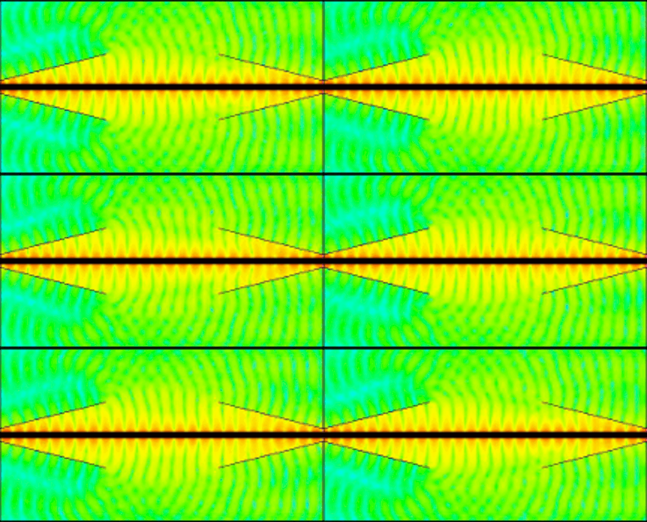
                And since we like a picture, here's one, linked from E-Line:Technology :

                Source: Animation of modeled E-fields for a TM mode wave propagating on a perfect conductor
                The animation above shows the modeled E-field for a pair of simple, uncompensated linearly tapered launchers mounted on a smooth, lossless conductor. The structure is excited by coaxial drive at the input of the left launcher. Energy is converted to surface wave, propagated along the central region of the conductor and received by the launcher on the right where it is coaxially terminated.

                Colors represent logarithmic E-Field magnitude which spans a very large range. The highest field intensity by far is located in the red and orange region quite close to the central (black) conductor. The other colors; yellow, green and blue represent greatly weaker field intensity but may help show interesting detail of the propagation mode.

                So, it looks like it is possible to transfer the energy using a single line, provided everything is tuned correctly.

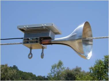
                The E-Line stuff suggests you may need these kinds of launchers in order to accomplish what Tesla wanted "I do not permit the energy to go out":

                So, it appears that if you use the earth as a transmission line by bringing it into resonance using a TMT, it works because of the presence of the atmosphere, while when using one wire to connect transmitter and receiver, you have to take extra steps in order to prevent radiaton into space.


                Update: Coming to think of it, it may be worthwhile to try and take a coax cable for the one-wire connecting transmitter and receiver, provided everything is tuned correctly. IIRC, in the article about the E-line, they explained their e-line basically as a coax cable with the shield being somewhere at infinity.... So, you should probably be able to prevent radiation using a coax cable instead of an uninsulated wire.

                Update 2: Found some patents by Elmore, which show a.o. the construction details of the launchers/catchers: Directory contents of /pdf/Patents/Elmore/
                Last edited by lamare; 07-11-2011, 02:01 PM.

                Comment


                • #83
                  As far as actual testing and experimenting with this setup go's. I'm having a bit of trouble determining what is happening where, the scope shows a wave on it all the time, right to when I connect it where I want to measure.

                  I see two different size spikes on the negative end of the primary coil a big one then a slightly smaller one repeating. I see the same on the primary cap.

                  When the scope's not connected to anything it shows a nice sine wave.

                  Then if I scope the output coil of the receiver I see what looks like a pulse train from a PWM circuit coming out at 230 odd Khz Pulses WOW what comes out the receiver looks like what went in the transmitter almost exactly, I was a bit surprised by that I expected a sine wave over there too. So it seems that there is something not quite right yet or maybe that is how it should be I'm not sure.

                  I've got a strange load setup of 4x5mm LED's in parallel and another two in series but in parallel with the other four and there is about 900 uf of capacitance on the DC output the LED's burn bright and it holds 12 to 13 volts there. I can add a small fan but the votage drops .

                  I will try to get a power output reading tonight somehow from the output coil.

                  Cheers
                  Last edited by Farmhand; 07-11-2011, 12:28 PM.

                  Comment


                  • #84
                    Yes thats for sure the radiation should be reduced as much as possible for transmitting energy. When i connect the coils to ground the sine wave doubles in size and the radiation from the toroids is reduced a lot, a fluro needs to be put right up to almost touch it to light but then it stays lit when drawn right back away and neons are much duller close to the toroid too untill they touch. ( I still need to make some much better and smoother toroid terminals) I reduced the voltage at the terminals because I am using a 17 turn primary again now I was using a 5 turn one for a while.

                    However connecting to the ground increases the size of the wave on the scope but it also seems to put the receiver out of tune and reduce's it's output a little bit because of that, I haven't looked into fixing that problem yet.

                    Seems to me if a large pair of these was built to have a resonant frequency low enough and they were connected to the ground they would just work if tuned correctly. The actual construction of the Earthing system and the towers would take the most work and cost.

                    Comment


                    • #85
                      Hmm it seems as though I have made the coils so that I can only adjust them the wrong way from how I need to go. I think i need to remove turns from the output coil so the adjustment can make up for it.

                      I don't think the goal is to use any wire's or conductors at all between them lamare it's just convenient, when I want to try to do any reasonably long distance transmission tests here from say one side of the paddock to the other it will have to be done either using either the electric fence wire instead of the ground or preferably the ground itself. It wouldn't make any sense to build two small ones for experimenting with without trying them with a wire between as well as using the ground, i'll be trying and comparing lots of things.

                      I won't be upset if these little things don't work well using the ground because of the very low power, but I already know they do work because I tried it, I've only tried it the way it was setup last week before I changed a lot of stuff, when i tried it then the sine wave went almost flat when i connected it to the ground but it did light the LED a bit, there was a tiny bit of power transfered then using the ground, I don't think I mentioned it then because it was not worth mentioning, now since the changes I made a couple of days ago the sine wave doubles in size when I connect to ground so I am a little more confident I'll get a better result this time.

                      One thing is for sure is that it transmitts a lot more power now than it did then "at least double" and more efficiently too. I just need to be carefull that any changes I make now are improvements and not ummm unimprovements. What is the opposite term to "improvement" ?

                      Slow and steady change's from now on.

                      I need to test this again soon with 12 volts so I can go ahead and give 24 volts a whirl just for the coil supply.

                      Cheers

                      Comment


                      • #86
                        A DIY Tesla Coil Tuner

                        The Tesla Coil Tuner (TCT) is a simple and low cost signal source that can be used to find the resonant frequencies of the primary and secondary circuits of Tesla coils. It uses simple commonly available parts. It can be assembled in a few hours with minimal electronic skills. The cost of all the parts is about .
                        The TCT is simply a LMC555 IC square wave generator. An audio taper pot and a 2% polypropylene timing capacitor control the 50% duty cycle oscillator's frequency.

                        A bi-color LED in series with the output senses the current being drawn and a frequency dial indicates the frequency setting.


                        RMCybernetics - DIY Homemade Tesla Coil Tuner

                        Signs and symbols rule the world, not words nor laws.” -Confucius.

                        Comment


                        • #87
                          Originally posted by Farmhand View Post
                          I don't think the goal is to use any wire's or conductors at all between them lamare it's just convenient, when I want to try to do any reasonably long distance transmission tests here from say one side of the paddock to the other it will have to be done either using either the electric fence wire instead of the ground or preferably the ground itself. It wouldn't make any sense to build two small ones for experimenting with without trying them with a wire between as well as using the ground, i'll be trying and comparing lots of things.
                          Let me first pull in the discussion from the Yahoo group "jk_wireless":
                          jk_wireless : Jackson's Wireless Power Transmission

                          There, we have the same discussion:
                          Yahoo! Groups
                          From what I observe I still believe that a longitudinal wave is in fact present between the two spheres, but since the transmission is not earth supported but only wire supported, it weakens very quickly with distance. If one could find a way to replace the ground wire by two properly grounded earth connections and then tune in on the frequency of the earth, I’m quite convinced that the transmission wave would stand up over a much longer distance. But this is just a layman’s guess.
                          Let's first first go to this excellent article on Tesla's Wireless system here which describes the history of Tesla's inventions that led to his Wireless idea very good:
                          http://www.andre-waser.ch/Publicatio...essSystems.pdf
                          (Copy here: http://www.tuks.nl/pdf/Reference_Mat...essSystems.pdf )

                          Then on September 1897 TESLA[24],[25] has filed two other patents for the transmission of electrical energy (figure 4). But the granting of this patent has been made dependent of the experimental success as a corresponding part in the patent shows (Pat. 645‘576, p. 3, col. 2). In this patents TESLA writes of a grounded high frequency emitter with a highly elevated ball electrode which was in resonant connection with a symmetrical, grounded resonant circuit (receiver) to enable the energy transmission through the upper atmosphere, which in great heights becomes more and more conductive for electrical currents.
                          On the first glance to the series of figure 2 to 4 one supposes that the energy transmission finally occurs through the air by the means of an increasing electric conductivity of the upper atmosphere. Actually TESLA[24],[25] has written in his first patents that this is the case. But with a closer look at his drawings there can be recognized that all his circuits has – beneath the high voltage transformers – an other common thing: the ground connection. In later publications TESLA[32],[36],[32] has mentioned explicitly that the really conductor of the power transmission is the Earth itself. The Earth acts like a giant reservoir for electrical charges which can be set into oscillation by his powerful equipment. Is now a very sensitive resonant circuit (receiver) placed on an other place on Earth, which is tuned to the transmitter‘s frequency, then the receiver couples to this oscillations and gains its signals due to resonance.
                          The force of an oscillating HERTZ dipole on a stationary charge is well known. This can also be described as a sum of forces between relatively resting, moving and accelerating charges as the author[45] has shown for the case of large distances to the HERTZ dipole. A transmission of electrical energy from one point to an other is certainly possible with a HERTZ dipole, too. But with increasing distance r form the transmitter the energy density diminishes rapidly. This law of distance can be undergone when instead of air under normal pressure a conducting medium (electrical wire) is used. An almost frictionless transmission of electrical energy between two points on Earth without wires only can be done by using some sort of a ‘connecting wire’, a voltage or current source and a load. This connecting wire is the Earth. The voltage or current source is the transmitter and the receiver is the load.
                          The elevated terminals D and D‘ function as a charge reservoir (electric capacitor), butthey do not act as the transmitting terminal itself, whereas the energy is given off to the air. [...] TESLA has operated the Earth as a ball capacitor. The transmitter “pumps” with a frequency between 20...250kHz[24],[32] electrons between the Earth and the elevated terminal back and fourth. To minimize the HERTZ radiation losses this frequency has to be as low as possible, as TESLA has mentioned explicitly. To achieve an optimal effect it is necessary to use high voltages.
                          Tesla illustrated this himself in an article "THE TRANSMISSION OF ELECTRICAL ENERGY WITHOUT WIRES" on March 5, 1904, which you can find at:
                          Transmission of Electrical Energy Without Wires

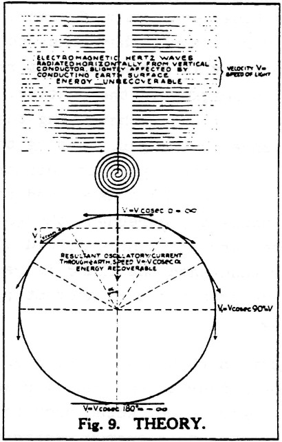
                          He used the following illustration to show the difference between electromagnetic radiation (either "Herzian" or longitudinal, btw) and his system:


                          The text in the upper part of the picture reads:
                          Electromagnetic Hertz waves radiated horiontally from vertical conductor, slightly affected by conducting Earth surface.
                          ENERGY UNRECOVERABLE
                          Now why is this so important? Because no matter what kind of waves are transmitted from the vertical conductor, with or without a sphere on top, the energy radiates away in all directions and is therefore lost for all but a very small fraction!

                          This same picture is also printed in Eric Dollard's book, with the following comment:
                          Tuks DrippingPedia : Theory Of Wireless Power

                          It can therefore be seen that while the transmission of transverse waves involves the spraying of energy, with its consequent square law diminishment of energy density, and no hope of retrieving the unused energy, the Tesla system involves the direct connection of transmitter and receiver, via the pulsating lines of electric induction. Therefore, the transmitter and receiver are rendered as one apparatus.
                          Now back to Waser's paper, where we find the following:

                          If the Earth is electrically struck – for example by lightning – there will always be at least two basically different resonances. The main resonance between Earth and atmosphere is known as SCHUMANN resonance[14],[15] and has a frequency of about 7.9 Hz, whereas the TESLA resonance is 11.8 Hz. Both different resonances are again presented in figure 8.
                          Basically, the Schuman renonance is a (transversal) surface wave, while Tesla's resonance consists of a longitudinal pressure wave going trough the earth. The speed of the longitudinal wave going trough the earth is pi/2 times c, the speed of light.

                          The main longitudinal resonance is 11.79 Hz. With this longitudinal wave of free electrons in the ground the whole Earth is set in resonance. The Earth diameter must be an odd multiple of a quarter wavelength of the transmitter. Then, to produce a forward and backward wave front, the signal must be applied at least for 0.085 seconds to achieve a standing wave. And exactly all this numbers are given in TESLA’s patent[32].
                          One more interesting quote:
                          The assumption[10]-b, that TESLA has received more energy than transmitted – and therefore gave his system the name „Magnifying Transmitter“ – can neither be definitively confirmed nor rejected with the presented analysis.
                          What can be concluded most of all is that Tesla did not use the main longitudinal resonance frequency of 11.79 Hz, but in the order of 1000 times higher. In other words: he was using higher order resonance. Some time ago, I started writing an article on free energy at Peswiki ( Article:Free Electric Energy in Theory and Practice - PESWiki ). The first part of this article explains why the electric field as emitted by charge carriers can be considered to be an energy source, because charge carriers continuously convert energy from the zero-point field into a propagating static electric field. When you combine that with Bearden's "Don't kill the dipole" concept, you have the theoretic foundation for building free energy devices. I never finished the article, but when you put either a coil, an antenna or a transmission line into a higher order resonance, such that a standing wave travels along the coil/antenna/transmission line, it is clear that you only drive one of the dipoles in the whole resonating system, while all the other ones are powered by the zero-point field.

                          So, to me it is clear that higher order resonances are the most simple way to tap the zero-point field in order to get your hands on this clean, free and limitless energy source known as the zero-point field. And you find this principle back in a lot of inventions that claim to produce free energy, seemingly out of nothing, like Meyer/Puharich's car on water, Tesla's magnifying transmitter, Kapanadze's Kapagen device, the Joule-thief, etc. That's why I proposed to build a solid state Kapagen-like device, as I posted here:
                          http://www.energeticforum.com/146489-post1921.html I have wound a coil, but so far I did not get it working, because it drew that much current that the fuse of my DMM blew: http://www.energeticforum.com/renewa...tml#post146535


                          Now finally, back to your questions. First of all, yes, there are longitudinal waves being transmitted/exchanged between the transmitter and reciever balls. The point is that these radiate in all directions, no matter whether they are electromagnetic (Herzian) waves or Tesla's longitudinal waves. Both kind of waves diminish very rapidly when not quided such as to form a standing wave, because the energy is sprayed into space in both cases!!!!

                          In Tesla's own words:
                          Nikola Tesla On His Work With Alternating Currents -- Chapter IV
                          I prefer to reduce those waves in quantity and pass a current into the earth, because electromagnetic wave energy is not recoverable while that [earth] current is entirely recoverable, being the energy stored in an elastic system.
                          So, to sum this up:
                          Yes, longitudinal waves as well as transversal waves are transmitted by your sphere/coil arangement. And yes, you can detect them at some distance and use them to transfer energy over a small distance. The point is that this kind of energy radiaton should be avoided as much as possible, because all energy radiated into space is wasted can cannot be recovered. And the energy gain that Tesla found, and which is why he called his invention the "Magnifying Transmitter", is to be found in the higher order resonance standing wave in/along the "ground" connection between transmitter and receiver.

                          So, the critical component in a magnifying system is the "ground" connection between transmitter and receiver, which should be in higher order resonance and non-radiating. And that is the essential difference between the transmission of energy "trough the air" and Tesla's system.
                          Last edited by lamare; 11-01-2011, 08:54 PM. Reason: small textual improvement

                          Comment


                          • #88
                            Thank you very much lamare you sure can gather a lot of information.

                            It'll take me quite some time to digest all that info, but I will try my darndest to understand. I'll start right now.

                            Thank you.

                            Monsieur that looksl ike a handy little unit for tuning coils.

                            Thank you too.

                            Comment


                            • #89
                              So some usefull information would be the frequencies of the higher order harmonics of 11.79 Hz. I wonder how to work that out.

                              I would agree that more power needs to be used than what be be got from a function generator. And the higher the voltage used the better.

                              It strikes me that my electric fence conducts through the ground quite well, and I know that there can be no comparisons between an electric fence and a magnifying transmitter, however the fact remains the electric fence does conduct energy through the ground very well at very very low frequency about 1 cycle every 1.5 seconds at quite large distance. And electric fence's can be fried by lightning strikes to the ground going through the ground and up the ground conection to the fence energiser. Not just by lightning striking the wire which is isolated or insulated from the ground. Seems the lightning wants to go into the capacitance of the elevated wires or something.

                              So it occurs to me that as long as a resonant transformer is connected to ground well and constructed according to Tesla's patent paying close attention to reducing the radiations from the terminal as much as possible and an identical one was built at a distance and also connected to ground then they were tuned to a higher resonance of or 11.79 Hz and the terminals charged to a very high potential. Then they would just work.

                              All that needs to be done is to acheive a compatable frequency at resonance with enough potential and limit the radiation enough.

                              I still think I was missunderstood.

                              My only contention when mentioning that a Magnifying trnsmitter can emitt electromagnetic radiation was that if someone was to build a pair going by Tesla's patent and tuned them to operate as Tesla states they would work as he states with logitudinal waves I do not dispute that and never did dispute that.

                              My contention is that the system can then be put out of tune and the terminal made to leak so as to emitt generous radiations if the owner of the magnifying transmitter so wishes to do that, they can do it. Tesla said that can be done if one wishes, There wouldn't be much use for it but it can be done. Just because a Magnifying transmitter is out of tune does not make it something else.

                              By reducing the radiations no energy is lost, I understood this all along.

                              Having said that, the information you have presentind lamare is very usefull of course and I very much appreciate it, and i will be refering to it regularly.

                              Cheers

                              Comment


                              • #90
                                12 Hz doesn't seem likey as a frequency for Tesla to have used to me I might be wrong, but I think he used up to 20 Khz and different frequncies. I've read so much I can't remember here i read that.

                                Comment

                                Working...
                                X