Announcement

Collapse
No announcement yet.

Tesla's Magnifying Transmitter "Replications"

Collapse
X
 
  • Filter
  • Time
  • Show
Clear All
new posts

  • #91
    So do you think a Don Smith device or a Kapagen type setup would be best for making lots of home power ?

    Because I think I agree with that and you're coil design is interesting to me too. I have wire and stuff and I would love to test out some of you're designs lamare, they make sense to me.

    Comment


    • #92
      Originally posted by Farmhand View Post
      12 Hz doesn't seem likey as a frequency for Tesla to have used to me I might be wrong, but I think he used up to 20 Khz and different frequncies. I've read so much I can't remember here i read that.
      Well, to refer to your other question:
      So some usefull information would be the frequencies of the higher order harmonics of 11.79 Hz. I wonder how to work that out.
      The higher order harmonics are at a whole number times this 11.79 Hz for the use of the Earth as a resonator. One of them would be at 1697 * 11.97 = 20007.63 Hz. The next one would be at 20019.6 Hz. So, there are many, many, many harmonics of 11.79 around any frequency in the kHz range

      And if the magnification effect indeed is like I think it is, then you get an enormous multiplication of the energy, since you have to provide only the energy to keep one dipole of the standing wave going, the other 1696 in this calculating exercise are powered by the zero-point field for free


      So, if you want to check wether or not this theory works out like I think it will, you could connect transmitter and reciever trough a coax cable with a length equal to a whole number of wavelengths corresponding to your oscillation frequency. If your oscillation frequency equals 1 MHz, you have a wavelength of 300 meters, so then you would at least need 300 meters of coax. Or maybe a 1/4 of that will also work, which would still mean 75 meters. If my understanding is correct, a coax of 300 meters for 1 Mhz may actually multiply 4 times, because you only have to drive 1/4 resonance yourself, but I am not sure.

      So, for practical testing, you may have to go to 10 MHz or higher (as Stiffler does), because otherwise you will have to invest in quite a lot of coax....


      Update: If you want to experiment with coax, you have to correct for the velocity difference between the air and the cable of choice, which equals 66% for RG-213, for example:
      Wave propagation speed - Wikipedia, the free encyclopedia

      So, if your oscillator runs at 10 MHz, you have a wavelength of 30 meters. In that case, if you use RG-213, the length of the coax cable should be a multiple of 0.66*30= 19.8 meters.
      Last edited by lamare; 07-12-2011, 01:40 PM. Reason: 1678 should be 1696

      Comment


      • #93
        Originally posted by Farmhand View Post
        So do you think a Don Smith device or a Kapagen type setup would be best for making lots of home power ?

        Because I think I agree with that and you're coil design is interesting to me too. I have wire and stuff and I would love to test out some of you're designs lamare, they make sense to me.

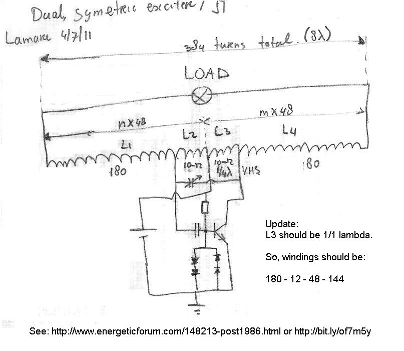
        Yes, I do. The Kapagen device appears to work along the principle of using higher order harmonics, of which you only have to drive one dipole in the set of dipoles formed in the standing wave. If that is correct, then my simple design should work and should scale up very well.

        But of course, the devil is in the details, so I may encounter some surprises and have to go back to the drawing board. OTOH: Kapagen's device does suggest this should be pretty close to a working design:

        http://www.energeticforum.com/renewa...tml#post146489


        Update: Link in the image: http://www.energeticforum.com/148213-post1986.html
        Last edited by lamare; 07-20-2011, 08:57 AM.

        Comment


        • #94
          Originally posted by lamare View Post
          Well, to refer to your other question:


          The higher order harmonics are at a whole number times this 11.79 Hz for the use of the Earth as a resonator. One of them would be at 1697 * 11.97 = 20007.63 Hz. The next one would be at 20019.6 Hz. So, there are many, many, many harmonics of 11.79 around any frequency in the kHz range

          And if the magnification effect indeed is like I think it is, then you get an enormous multiplication of the energy, since you have to provide only the energy to keep one dipole of the standing wave going, the other 1678 in this calculating exercise are powered by the zero-point field for free


          So, if you want to check wether or not this theory works out like I think it will, you could connect transmitter and reciever trough a coax cable with a length equal to a whole number of wavelengths corresponding to your oscillation frequency. If your oscillation frequency equals 1 MHz, you have a wavelength of 300 meters, so then you would at least need 300 meters of coax. Or maybe a 1/4 of that will also work, which would still mean 75 meters. If my understanding is correct, a coax of 300 meters for 1 Mhz may actually multiply 4 times, because you only have to drive 1/4 resonance yourself, but I am not sure.

          So, for practical testing, you may have to go to 10 MHz or higher (as Stiffler does), because otherwise you will have to invest in quite a lot of coax....
          Oh yes I see, now I get it. Thanks for being so patient lamare you are a true saint. That does make sense.

          Comment


          • #95
            I see great posts here The problem I see with higher then 1Mhz frequency is because of interaction with load. I think such high frequency we can only store in capacitors and discharge at lower rate.It may look like a weak current for any other loads due to wrong impedance.Just my two cents.

            Comment


            • #96
              OK so what I can do is put the shorter coil "B's" back in which sounds like a good idea now I have the function generator.

              They are fairly small, my Coil "A's" or the bottom part of the secondaries have about 55 meters of wire on them and the same 55m on the short coil "B's" the long coil "B's" I have on there now are 212 meters of wire.

              So at the moment I have 270 meter or so secondaries.

              I'll chuck one of the short ones in and find the new frequency which should be about 1Mhz or a bit more, then I'll know how much coax i'll need. Coax will be good for other things too. But I won't be able to get some for a week or two. So some time for other things inbetween.

              I noticed the update for the velocity correction too.

              Sounds like fun.

              Comment


              • #97
                Let me also shine some light on the significance of the pancake coil. I added the following note to Eric's book on my wiki:

                Tuks DrippingPedia : Theory Of Wireless Power

                Note: Paul Nicholson wrote an interesting piece on how the velocity factor, which appears to be the same as Dollard's propagation factor η, depends mostly on the h/d ratio of a coil:
                "Ed Phillips noticed that wire length divided by the free space wavelength of the quarter wave resonance of an unloaded coil was a smooth function of the h/d ratio and largely independent of the turn count. [...] Ed's observation recognises that the velocity factor for a coil is a function largely of the overall geometry of the coil and does not depend very much on how many turns are put in. This means that it is worth while defining a geometry factor with which to relate the velocity factor directly to the h/d ratio of the coil."

                This is the relation they came up with using curve fitting:

                Fres=(0.39*ln(h/d)+1.19)*75e6/l (Hertz)

                What is interesting from their observation that the velocity factor for a coil is a function largely of the overall geometry of the coil is that this connects very nicely to the Corums' model, noted above, whereby they consider a coil as a geometric construction conducting in one direction only.
                This refers to this document: http://www.tuks.nl/pdf/Reference_Mat...ity_Factor.pdf


                This article shows that the velocity factor goes to zero when the h/d ratio goes to zero. This means that a pancake coil is the easiest coil design to drive into a higher order resonance mode because the waves propagate trough it at much lower speeds compared to when they would travel trough the air, hence you easily get long wavelengts. So, it has low resonance frequencies and is therefore easy to drive into higher order resonance, and that is most likely why Tesla liked it so much.

                So far, so good.

                Now in order to be able to pick up all that energy in the multiple dipoles a higher order resonance mode in a coil consists of, you have to find a way to pick up the energy of all these dipoles, in this cause trough a coupled coil, the primary. And that means first of all that is very important to match the resonance frequencies of the primaries and the secondaries in your coil. The natural resonance frequency of your secondary (the center winding) should be a multiple of the primary one. They have to be matched to one another, IMHO, for maximum output.

                Update 2: Oops. That should be the other way around. The central, secondary coil has more windings than the primary and has therefore a lower resonance frequency. So, the self- or natural resonance frequency of the primary should be a multiple of that of the secondary.

                And the pancake coil, or better: pakcake transformer, is most suitable for picking up all the energy from in the large secondary, because all the windings as well as all the dipoles are in one plane, no matter how/where they are actually placed in 3D, even though I guess the wave pattern inside a pancake coil will look something like this:


                For a long, single wound coil, things get very complicated. How do you match the primary and secondary windings such that you are able to pick up energy from all the dipoles your standing wave consists of??


                And that is probably the reason why my idea of resonating two transformers did not work. I posted that here:
                http://www.energeticforum.com/renewa...tml#post146289

                Update: Note that with the Kapagen design, the energy is picked up by the same coil as the one creating/maintaining the dipoles c.q. the standing wave. So, that appears to be another possibility for getting your hands on the free energy picked up by the standing wave dipoles from the zero-point field.

                Update 3: While for a single-wound coil, it is more complicated to pick up the energy collected by the various dipoles in a coil resonating in higher order resonance, it is possible to do it. IIRC, Don Smith did this. He showed a coil sliding over a resonating coil which he used to tap energy with. See: Don Smith's Briefcase Device

                One thing i have found that he said is correct, that moving the primary coil by sliding it through the secondary coil, alters the primary and secondary resonant frequency by the same amount, and therefore acts as a frequency control for the device.
                As I said: more complicated....
                Last edited by lamare; 07-12-2011, 08:19 PM.

                Comment


                • #98
                  Connection to Puharich's water motorcycle

                  On the jk_wireless group comment about the dependence of distance between transmitter and receiver:

                  jk_wireless : Jackson's Wireless Power Transmission

                  Sounds like yuor setup is not tuned to transmit the way this experiment intends.

                  in myy setup and many others here the output at the receiver (and LED brightness) does not diminish with distance in any way, not at 7m, not at 30m.
                  I replied:

                  I don't have an actual setup myself, at least not at the moment. I have experimented with a variation of Stiffler's stuff 2 years ago:
                  http://www.energeticforum.com/renewa...html#post65420

                  However, I think it is very well possible to find a frequency/mode whereby you do not see the dependence of the distance outside the close range. As I remember from Meyl's video's, depending on the frequency used, either Herzian waves or what he tought to be longitudinal waves trough the air are dominant. Given that the whole train "transmitter sphere - transmitter coil - "ground" - reciver coil - receiver sphere" does also have an overall resonance mode, whereby the radiation from the "ground" wire is relatively small unless it's length is close to a multiple of 1/4 wavelength, you can vary the distance at will as long as the energy transfer trough the air from transmitter to receiver is relatively low.

                  So, this way you can transfer energy from transmitter to receiver with relatively low losses. But as far as I can tell you won't find the huge kinds of gains Tesla was aiming for either. All the gain you may find would be provided by your transmitter and receiver coils *if* these are driven into higher order resonance IMHO, even though that can already deliver you a very nice gain of up to 10 times, according to Meyl:

                  http://www.k-meyl.de/go/Primaerliter...y-Transfer.pdf
                  "The measured degrees of effectiveness lie between 140 and 1000 percent"

                  Now even though this is not directly related to replicating Tesla's Wireless System, let's take a little sidestep to Puharich's system, because there are many similarities.

                  I wrote about Puharich and Meyer's system in my 'article' at Pes:
                  Article:Free Electric Energy in Theory and Practice - PESWiki

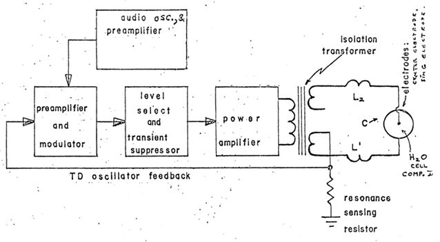
                  This is his main schematic:
                  Andrija Puharich: Water Decomposition by AC Elecrolysis >


                  He used a modulated signal to drive his fuel cell, about which he said:
                  This device has an output consisting of an audio frequency (range 20 to 200 Hz) amplitude modulation of a carrier wave (range 200 Hz to 100,000 Hz). The impedance of this output signal is continuously being matched to the load which is the second component, the thermodynamic device.

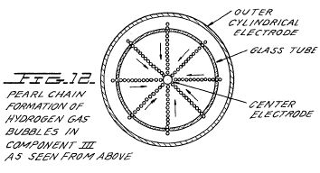
                  A very intriguing picture from his patent is this one:

                  Especially when compared to this one:

                  This shows very clearly that Puharich got the water inside his fuell cell into acoustic resonance and therefore matched the audio frequency signal he was modulating to the acoustic resonance frequency of the "water organ pipe" he was driving into resonance.

                  Originally posted by lamare View Post
                  I think you'd have to model the WFC like this:


                  On either sides, you have the capacitors between the fluid and the tube, because of the dielectric layer on the tubes. Now the characteristics of these capacitors depends mostly on the thickness of the layer. And these are non-linear capacitors. Below a certain voltage, depending on the thickness of the layer, they act as capacitors. Above that voltage, the dielectric breaks down and you get a shortcut. I have modelled this as a zener limiter:
                  Zener Diodes Information on GlobalSpec
                  However, the important part for this thread is this:

                  Originally posted by lamare View Post
                  If you look at what Meyer and Puharich did, then from an EE point of view, they have their load in between two coils, which are most likely resonating. But resonating such that the overall resonance, which would be over the whole load train (coil 1 - WFC - coil 2), is such that you have high voltage, low current at the driving terminals of your coils. And that would be so called half or full wave resonance.
                  When you take a look at his transformer and the coils L1 and L2, you have something very similar to Tesla's principal design, with some key differences, though.

                  First of all, there are no top spheres and secondly, the capacitive resonator being driven (Earth vs. a fuel cell) is driven in a distinctly different way.

                  Tesla arranged his system such that he was able to drive a current into his capative resonator, while Puharich arranged his system such that he was able to excite his capacitive resonator, whereby his plates were undoubtly covered by some thin insulating layer (dielectric) by means of a strong electric field. In other words: Puharich drove his load by a virtually current-less voltage across an insulated capacitive resonater, while Tesla drives a current into his capacitive resonator, probably because it was not so well insulated.

                  Update: Or maybe he just couldn't find a long enough wire to connect to the other capacitor plate located in the interior of the earth, aka Agartha

                  Since Tesla wanted to drive a current into the Earth, he needed some reservoir to temporary store the electrons he wanted to juggle back and forth into the Earth, and that is the main purpose of the top sphere. It is a capacitive load, which keeps the top of the coil at a relatively fixed potential, and therefore the standing wave will show a voltage node and hence a current antinode at the top, since "current" and "voltage" have a phase difference of 90 degrees in standing electro-magnetic waves:

                  See: Standing wave - Wikipedia, the free encyclopedia :

                  The effect is a series of nodes (zero displacement) and anti-nodes (maximum displacement) at fixed points along the transmission line.
                  Also see: Standing-waves
                  The standing waves of voltage and current appear together. Observe that one is maximum when the other is minimum. The current and voltage standing waves are one-quarter cycle, or 90 degrees, out of phase with one another.
                  So far, so good.

                  Now what I wanted to illustrate with this practical example is that you can get a gain of energy using higher order resonances, and that it is also possible to get a while load train into one single resonance mode, as I mentioned in my reply uquoted above.

                  Note that Puharich used the energy out of the higher-order resonating coils directly (as Kapanadze does in his Kapagen device), while Tesla transformed it down using a pancake transformer.
                  Last edited by lamare; 07-19-2011, 04:10 PM. Reason: undo last edit

                  Comment


                  • #99
                    G'day lamare, You're right I do see the similarity in the kapagan in that fuel cell circuit, don smith device, and the circuit you proposed as an exciter type setup when compared with the Tesla system, some seem like just two tesla coils stuck together by the bottoms with the load between the tops, and Dons looks like he uses the middle too.

                    Very interesting. I see now where you are coming from, you're trying to help nail down the big gain. I think you're on the right track and have been for a while. I never worry too much about gains but i'll take em if they come my way.

                    I'm concerned about the heat in my mosfet switch's, I think it is a result of circuit noise or improper switching. So I'm going to rewind my 6.5 inch toroidal transformer, Tesla converter style so it outputs AC. Maybe then if I can use the AC output to drive the Transmitter I can get a lot more power and tension into the primary coil. As well as take the circuit further away from the coils.

                    I'll wind it with about 22 turns per quarter, opposite coils connected in series and so forth as it shows in the patent. And drive it with an inverter type circuit for an AC output. The secondary has 136 turns on it so the voltage stepup will be small. Any idea's what voltage I would get like that with 12 volts input ? About 60 volts AC is my guess.

                    NIKOLA TESLA - Google Patents

                    So I'm a little distracted but I am still studying you're posts.

                    I had a little play with some sparks today, I used 24 volts on the input just to see what happened, was a bit of fun. Seemed like arcs going through the glass of the neon. Bit ropey looking too.

                    YouTube - ‪AlternateFarmhand1's Channel‬‏

                    Last edited by Farmhand; 07-13-2011, 10:27 AM.

                    Comment


                    • Hey Cody, I still don't have a way to adjust my top terminals yet but I seem to be getting quite good and efficient transfer using the 17 turn primary so i'm doing some testing today, testing is difficult by myself, it's ok if the transmitter is by the analogue scope I can fine tune by wave amplitude, but if I take the transmitter away from the scope, then in order to see the receiver LED lights change brightness "to tune the system" from 30 meters away in the daylight I need binoculars and even then it is not easy Maybe it'll be easier to see a voltmeter at the receiver with the binocs.

                      I don't have the wire yet to try longer distance but I have 6 LED's on the receiver now which is still not enough load for the output to exceede the input at idle.

                      I think last time I had only 5 volts over two leds and a 270 ohm resistor now I have 13 volts over 2 LEDs in series and a 270 ohm resistor in parallel with 4 LED's in parallel and a 1 k resistor. So 6 LEDs in total, holding 13 volts steady at about 3.5 meters. with about 250 Ma at 12.5 volts input just over 3 watts. If I connect a CD rom drive motor the voltage drops to about 7 volts.

                      All voltages measured on a analogue multi meter. I have no doubt I would do better with adjustable toroid terminals like you have.

                      Now to try at 30 meters or so.

                      Cheers

                      P.S. Some pre test pics. To set the bar, so to speak.
                      Input
                      https://skydrive.live.com/?cid=32a91...1311&sc=photos

                      Ouput
                      https://skydrive.live.com/?cid=32a91...1310&sc=photos
                      Closer
                      https://skydrive.live.com/?cid=32a91...1309&sc=photos

                      And here's a shot of second receiver next to first receiver with just the bottom of his coil connected to the bottom of the other coils. The resonant frequency of second receiver is 1666 Khz but the primary is not tuned to a harmonic, yet.
                      https://skydrive.live.com/?cid=32a91...1306&sc=photos

                      Last edited by Farmhand; 07-14-2011, 02:03 AM.

                      Comment


                      • OK I got about the same result as last time relatively. The voltage at the receiver halved to 6 volts. Some LED's are glowing a bit.
                        https://skydrive.live.com/?cid=32a91...1313&sc=photos

                        And the wave increased in size, which I now know can be a bad thing.
                        https://skydrive.live.com/?cid=32a91...1312&sc=photos

                        Some observations were that the further away I move the receiver the bigger the wave got on the scope which meant to me more voltage at the transmitter top terminal (toroid) and increased input current too, the increased voltage cause a lot of energy to be lost ( leaked ) out of the top terminal which was wasted ( i could see this by holding a neon near the transmitter the distance i held it and had it glow was more than trippled to several feet, normally only a few hundred millimeters), the rest of the energy that was not leaked was used at the receiver and in the heat produced in the mosfet switch's which were fairly warm.

                        From what I can tell, because the transmitter is in a steel shed none of the radiated energy would have made it to the receiver or very little.

                        Wirelessly lighting a 2 foot fluro from the transmitter also indicated the increase in radiated energy being much easier to do from a distance same as neon. The leakage can be tested I think with a neon, fluro or similar one of those AV plug thingy's might work too not sure about that.

                        So my conclusion at this point is that I need to construct some very much better top terminals as smooth as possible and adjustable like Cody's arrangement. So that the terminals "Do Not Leak Energy".

                        I also think my primaries are 1 or two turns too many.

                        Then get some long coax cable, the cables I used had very poor joins and the joins were uninsulated.

                        As long as no energy leaks out I don't see where it could possibly go except through the connection between the two coils to the receiver and whatever is not used or leaked out there should come straight back again at which point more would be added to maintain resonance if necessary. Anything else is a bonus.


                        Oh and it just occured to me to acknowledge that I think there was likely a fair amount of energy lost from the joins in the wire and the wire itself, which I think is what lamare said and why coax might help.
                        Last edited by Farmhand; 07-14-2011, 08:25 AM.

                        Comment


                        • Originally posted by lamare View Post
                          Yes, I do. The Kapagen device appears to work along the principle of using higher order harmonics, of which you only have to drive one dipole in the set of dipoles formed in the standing wave. If that is correct, then my simple design should work and should scale up very well.

                          But of course, the devil is in the details, so I may encounter some surprises and have to go back to the drawing board. OTOH: Kapagen's device does suggest this should be pretty close to a working design:

                          http://www.energeticforum.com/renewa...tml#post146489


                          Just tested my design. I used a BD139 transistor, and I can light a fluorescent tube of 8W nicely with it while drawing about 170 mA at about 10.5 V from the PS, but I don't seem to able to get any current out of the coil as I was aiming for, even though I haven't tried to charge a cap trough a diode bridge yet.

                          What is interesting is that I get pretty high (BEMF) spikes at the coil connection to collector of the transistor, about 40V high and with a frequency of about 5 MHz, while at the coil connection to the couple cap to the base of the transistor, I get a more sine-like wave, with the same frequency, of course.

                          I think this spike is important for getting the high voltage needed for lighting a fluorescent, because it contains many higher harmonics because of the sharp rising edge.

                          But still: back to the drawing board, I'm afraid, cause we already know how to light a fluorescent with these kinds of circuits.


                          It may be possible to work further along the design Puharich used in his water fuel cell:


                          He used this to get his fuel cell into acoustic resonance, by modulating his oscillator with a signal matching the resonance frequency of his WFC. So, if you can get a WFC in resonance using modulation, it should be possible to also get a low frequency electric resonant circuit into resonance using the high voltage from a HF transformer as described above. Puharich's modulator does not look too complicated to build:


                          I thought in this direction before, but I never came to build it:
                          Article:Free Electric Energy in Theory and Practice - PESWiki

                          But have to think about this more. You probably need to make the resonance circuit with coils as well as capacitors, so you get a low resonance frequency, while the caps can deliver/store the charge carriers to get a decent current trough your transformer primary.

                          Will sleep over it the coming night...

                          Update: posted some pictures here:
                          http://www.energeticforum.com/renewa...tml#post147952
                          Last edited by lamare; 07-17-2011, 12:04 PM. Reason: fluorescent turns out to be 8W

                          Comment


                          • Hi guys, I've been messing around with with an inverter/converter setup, I think I finally wound it right after three go's at winding the second coil set.

                            Video clip
                            ‪AlternateFarmhand1's Channel‬‏ - YouTube

                            Winding diagram.
                            https://skydrive.live.com/?cid=32a91...1316&sc=photos

                            I hope to be able to run the transformer at the resonant frequency of my transmitter coil so I can excite the transmitter primary with an AC wave that has a bit more amplitude than 12 volts, mabe it will work maybe it won't.

                            Cheers

                            P.S. lamare, i'm rushed for time and will reply to you're last post soon, I gotta run.
                            Last edited by Farmhand; 07-17-2011, 02:56 AM.

                            Comment


                            • Oh I almost forgot, I found that by adding this dual charging circuit, the two diode's, inductors and caps, arranged as per the Tesla ignition coil patent, I can do the same thing with half the input current, wow. I can demonstrate it, but the video hours are adding up. ( I built the charging circuit on a plastic buisness card ) .

                              https://skydrive.live.com/?cid=32a91...1319&sc=photos

                              At first glance it seems the two little inductors are pulling in half the required energy by way of thier magnetic field energy. But that may not actually be the case, it looks like it though. The output might be diminished now that I think about it, due to increased inductance, or reactance or something technical like that.

                              Cheers

                              P.S. Now seems like a good time to show this diagram of Walter's regarding Wave's.

                              https://skydrive.live.com/?cid=32a91...1320&sc=photos

                              ..
                              Last edited by Farmhand; 07-17-2011, 04:53 AM.

                              Comment


                              • Longitudinal Waves

                                Originally posted by 7imix View Post
                                there ARE longitudinal waves, but not in the air. In the earth conductor. This can be tested by checking the transmission speed over long distances. It should work out to be pi/2 * the speed of light, according to dollard.
                                I would like to know what method Dollard used to calculated it to be pi/2 * c. Classically the frequency of the emitter always exactly matches that of the wave that is emitted. However, the frequency of an emitted photon from an atom does not match the emitter in any of it's unexcited or stable states (there's an explanation for this later in the post).

                                In the Bohr model since m was considered a constant during excitation, the electron’s velocity inside the atom would have had to be reduced by a factor of 2 when a 4 fold reduction in absolute energy occurred. But in the hypothesis of this paper, since the velocity associated with the electron inside the atom is a constant during excitation or transition(which is Znidarsic's constant of 1.094x10^6 m/s), the electron’s mass is shifted by a factor of 4 when there is a 4 fold shift in energy during excitation (This is extremely important as you will see at the close of this post). In terms of electron momentum the Bohr model thus assumed the electron’s momentum was reduced by a factor of 2 when the electron went from the ground state to the first excited state, while the above paper suggests the electron’s momentum is reduced by a factor of 4.

                                In every Bohr orbital the electron carries an integer multiple of Planck's constant. This is because the period of the harmonic motion of the electron equals 2pi / omega. Since it's a multiple of Planck's constant, then this is also related to Znidarsic's constant. Using Dollard's formula of pi/2 * c we get 4.709×10^8 m/s. Now, taking 4.709x10^8 meters per second / 1.094x10^6 (Znidarsic's Quantum Transitional Velocity) we get 430.4 m/s. 430.4 m/s is very near to the speed of sound in dry air at 68 degrees Fahrenheit. This is a mechanical or sound wave, and sound waves are longitudinal. This mechanical wave occurs during the transitional stage of transferring energy.

                                Dollard's first half of his formula is pi/2 = 1.57 while the first half of the harmonic motion of the electron is 2pi = 6.28. 6.28 / 1.57 is exactly 4. This is a perfect match to the 4 fold shift in energy mentioned in the above publication, and I don't think it can be stressed enough. I don't think Dollard took into account the electron's mass being shifted by a factor of 4 and the electron's momentum being reduced by a factor of 4. Taking this into account, then we arrive at the speed of sound in the air during the quantum transitional states instead of 4.709×10^8 m/s.

                                The emitted photon which is an electromagnetic wave that propagates away from the atom must match the frequency of the emitter, and the emitter in this case, is the excited or transitional state itself and not any of the stable states. This is because a photon is only emitted or captured during a state of transition.

                                GB
                                Last edited by gravityblock; 07-17-2011, 09:13 AM.

                                Comment

                                Working...
                                X